2007 ISUZU KB P190 ESP
[x] Cancel search: ESPPage 3386 of 6020
Engine Management – V6 – Diagnostics Page 6C1-2–108
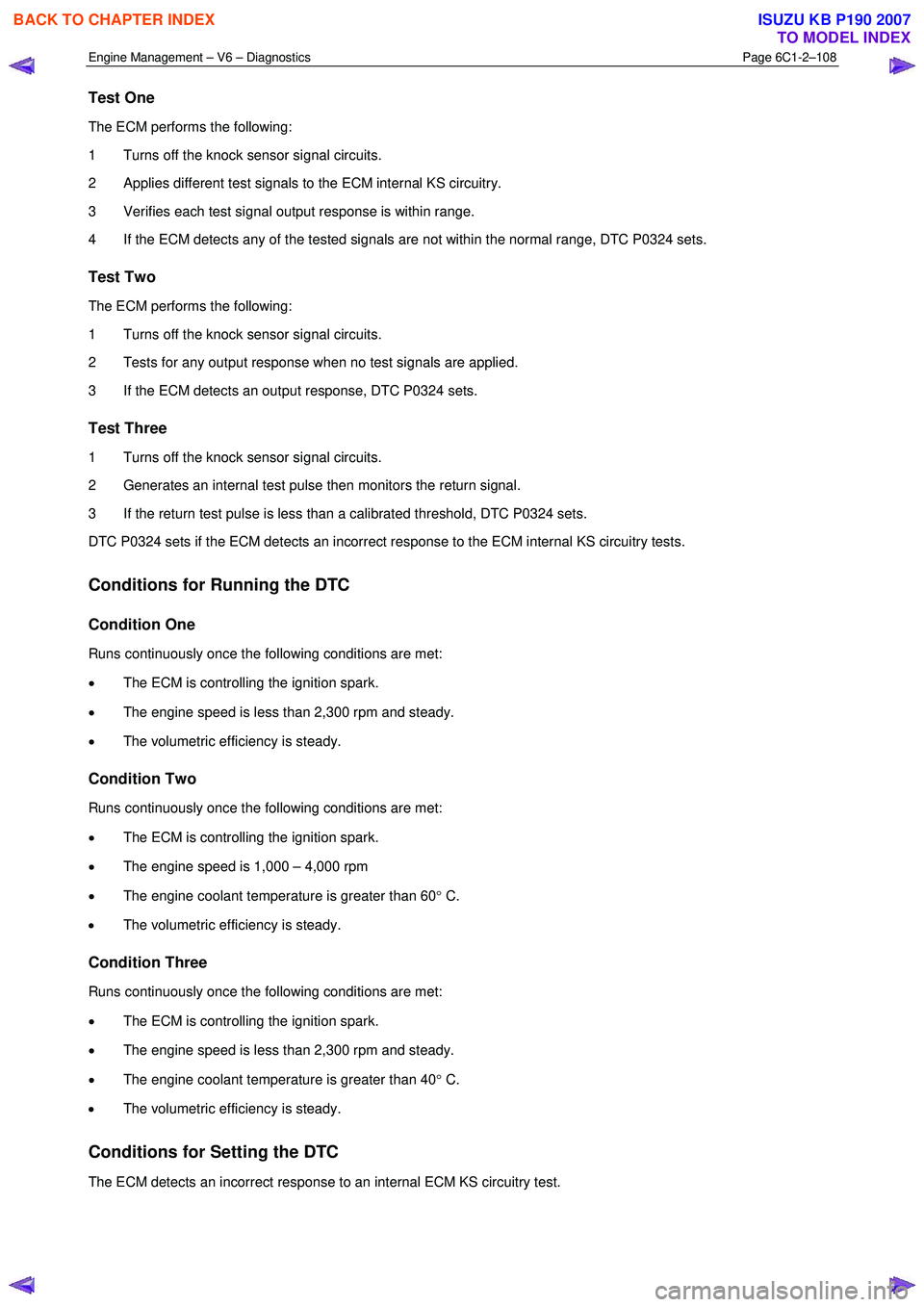
Test One
The ECM performs the following:
1 Turns off the knock sensor signal circuits.
2 Applies different test signals to the ECM internal KS circuitry.
3 Verifies each test signal output response is within range.
4 If the ECM detects any of the tested signals are not within the normal range, DTC P0324 sets.
Test Two
The ECM performs the following:
1 Turns off the knock sensor signal circuits.
2 Tests for any output response when no test signals are applied.
3 If the ECM detects an output response, DTC P0324 sets.
Test Three
1 Turns off the knock sensor signal circuits.
2 Generates an internal test pulse then monitors the return signal.
3 If the return test pulse is less than a calibrated threshold, DTC P0324 sets.
DTC P0324 sets if the ECM detects an incorrect response to the ECM internal KS circuitry tests.
Conditions for Running the DTC
Condition One
Runs continuously once the following conditions are met:
• The ECM is controlling the ignition spark.
• The engine speed is less than 2,300 rpm and steady.
• The volumetric efficiency is steady.
Condition Two
Runs continuously once the following conditions are met:
• The ECM is controlling the ignition spark.
• The engine speed is 1,000 – 4,000 rpm
• The engine coolant temperature is greater than 60 ° C.
• The volumetric efficiency is steady.
Condition Three
Runs continuously once the following conditions are met:
• The ECM is controlling the ignition spark.
• The engine speed is less than 2,300 rpm and steady.
• The engine coolant temperature is greater than 40 ° C.
• The volumetric efficiency is steady.
Conditions for Setting the DTC
The ECM detects an incorrect response to an internal ECM KS circuitry test.
BACK TO CHAPTER INDEX
TO MODEL INDEX
ISUZU KB P190 2007
Page 3418 of 6020
Engine Management – V6 – Diagnostics Page 6C1-2–140
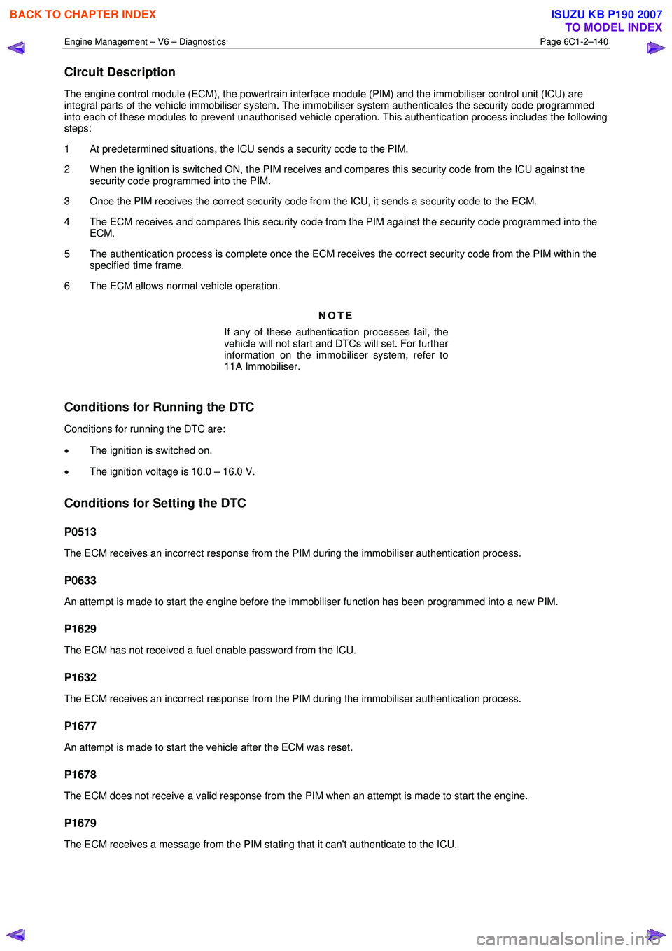
Circuit Description
The engine control module (ECM), the powertrain interface module (PIM) and the immobiliser control unit (ICU) are
integral parts of the vehicle immobiliser system. The immobiliser system authenticates the security code programmed
into each of these modules to prevent unauthorised vehicle operation. This authentication process includes the following
steps:
1 At predetermined situations, the ICU sends a security code to the PIM.
2 W hen the ignition is switched ON, the PIM receives and compares this security code from the ICU against the security code programmed into the PIM.
3 Once the PIM receives the correct security code from the ICU, it sends a security code to the ECM.
4 The ECM receives and compares this security code from the PIM against the security code programmed into the ECM.
5 The authentication process is complete once the ECM receives the correct security code from the PIM within the specified time frame.
6 The ECM allows normal vehicle operation.
NOTE
If any of these authentication processes fail, the
vehicle will not start and DTCs will set. For further
information on the immobiliser system, refer to
11A Immobiliser.
Conditions for Running the DTC
Conditions for running the DTC are:
• The ignition is switched on.
• The ignition voltage is 10.0 – 16.0 V.
Conditions for Setting the DTC
P0513
The ECM receives an incorrect response from the PIM during the immobiliser authentication process.
P0633
An attempt is made to start the engine before the immobiliser function has been programmed into a new PIM.
P1629
The ECM has not received a fuel enable password from the ICU.
P1632
The ECM receives an incorrect response from the PIM during the immobiliser authentication process.
P1677
An attempt is made to start the vehicle after the ECM was reset.
P1678
The ECM does not receive a valid response from the PIM when an attempt is made to start the engine.
P1679
The ECM receives a message from the PIM stating that it can't authenticate to the ICU.
BACK TO CHAPTER INDEX
TO MODEL INDEX
ISUZU KB P190 2007
Page 3462 of 6020
Engine Management – V6 – Diagnostics Page 6C1-2–184
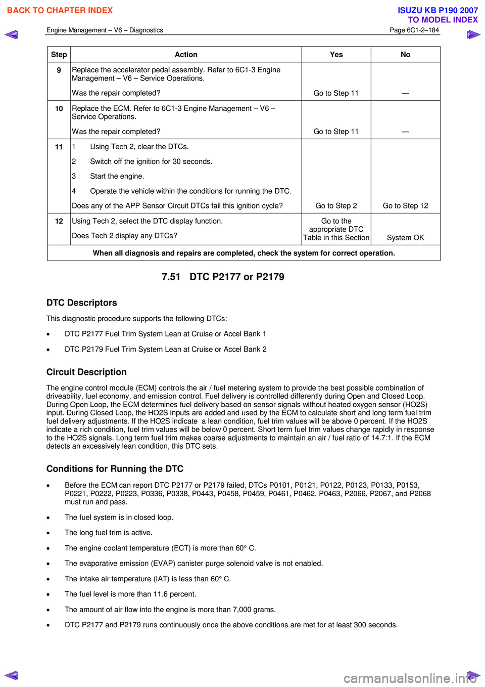
Step Action Yes No
9 Replace the accelerator pedal assembly. Refer to 6C1-3 Engine
Management – V6 – Service Operations.
W as the repair completed? Go to Step 11 —
10 Replace the ECM. Refer to 6C1-3 Engine Management – V6 –
Service Operations.
W as the repair completed? Go to Step 11 —
11 1 Using Tech 2, clear the DTCs.
2 Switch off the ignition for 30 seconds.
3 Start the engine.
4 Operate the vehicle within the conditions for running the DTC.
Does any of the APP Sensor Circuit DTCs fail this ignition cycle? Go to Step 2 Go to Step 12
12 Using Tech 2, select the DTC display function.
Does Tech 2 display any DTCs? Go to the
appropriate DTC
Table in this Section System OK
When all diagnosis and repairs are completed, check the system for correct operation.
7.51 DTC P2177 or P2179
DTC Descriptors
This diagnostic procedure supports the following DTCs:
• DTC P2177 Fuel Trim System Lean at Cruise or Accel Bank 1
• DTC P2179 Fuel Trim System Lean at Cruise or Accel Bank 2
Circuit Description
The engine control module (ECM) controls the air / fuel metering system to provide the best possible combination of
driveability, fuel economy, and emission control. Fuel delivery is controlled differently during Open and Closed Loop.
During Open Loop, the ECM determines fuel delivery based on sensor signals without heated oxygen sensor (HO2S)
input. During Closed Loop, the HO2S inputs are added and used by the ECM to calculate short and long term fuel trim
fuel delivery adjustments. If the HO2S indicate a lean condition, fuel trim values will be above 0 percent. If the HO2S
indicate a rich condition, fuel trim values will be below 0 percent. Short term fuel trim values change rapidly in response
to the HO2S signals. Long term fuel trim makes coarse adjustments to maintain an air / fuel ratio of 14.7:1. If the ECM
detects an excessively lean condition, this DTC sets.
Conditions for Running the DTC
• Before the ECM can report DTC P2177 or P2179 failed, DTCs P0101, P0121, P0122, P0123, P0133, P0153,
P0221, P0222, P0223, P0336, P0338, P0443, P0458, P0459, P0461, P0462, P0463, P2066, P2067, and P2068
must run and pass.
• The fuel system is in closed loop.
• The long fuel trim is active.
• The engine coolant temperature (ECT) is more than 60° C.
• The evaporative emission (EVAP) canister purge solenoid valve is not enabled.
• The intake air temperature (IAT) is less than 60° C.
• The fuel level is more than 11.6 percent.
• The amount of air flow into the engine is more than 7,000 grams.
• DTC P2177 and P2179 runs continuously once the above conditions are met for at least 300 seconds.
BACK TO CHAPTER INDEX
TO MODEL INDEX
ISUZU KB P190 2007
Page 3466 of 6020
Engine Management – V6 – Diagnostics Page 6C1-2–188
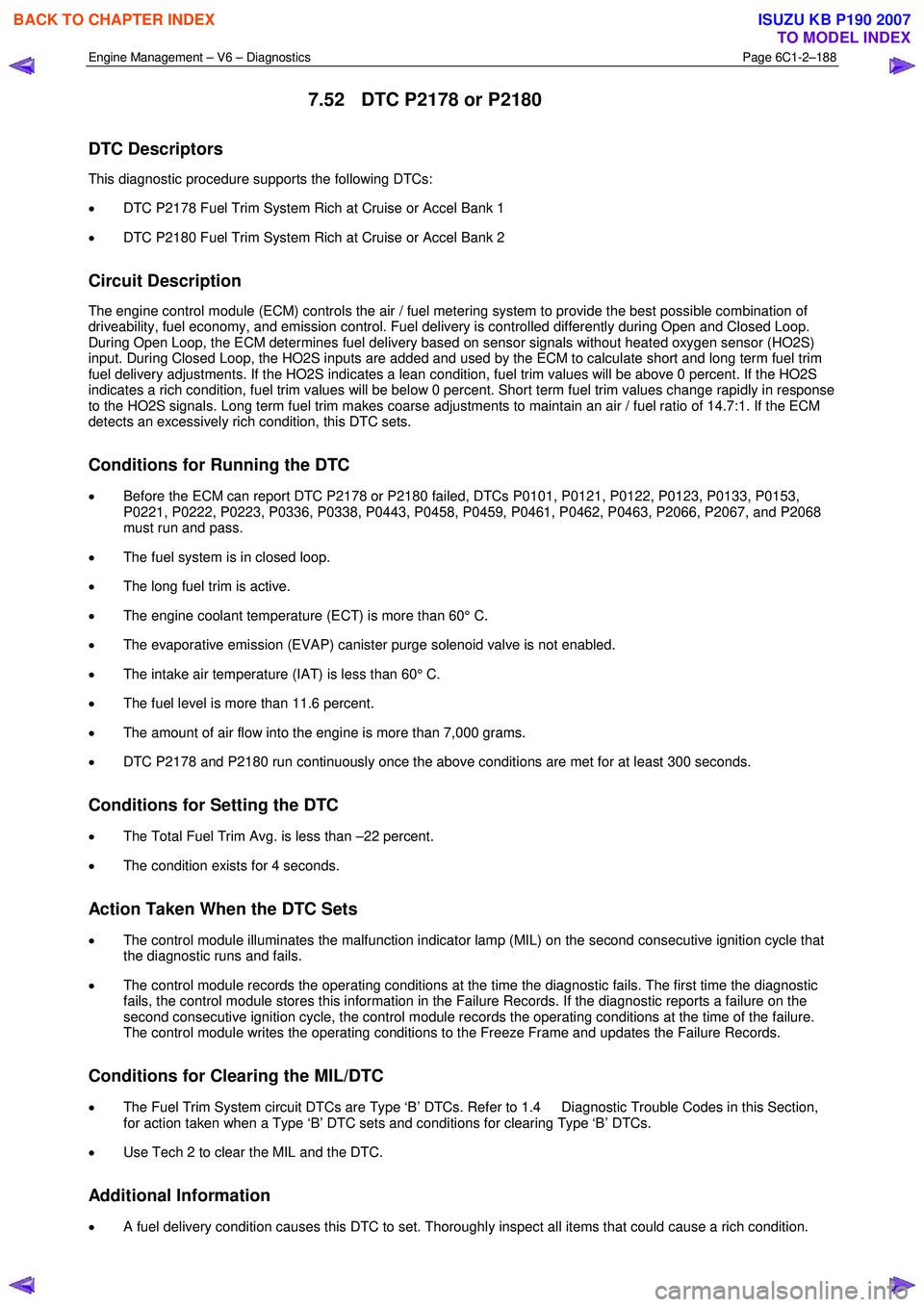
7.52 DTC P2178 or P2180
DTC Descriptors
This diagnostic procedure supports the following DTCs:
• DTC P2178 Fuel Trim System Rich at Cruise or Accel Bank 1
• DTC P2180 Fuel Trim System Rich at Cruise or Accel Bank 2
Circuit Description
The engine control module (ECM) controls the air / fuel metering system to provide the best possible combination of
driveability, fuel economy, and emission control. Fuel delivery is controlled differently during Open and Closed Loop.
During Open Loop, the ECM determines fuel delivery based on sensor signals without heated oxygen sensor (HO2S)
input. During Closed Loop, the HO2S inputs are added and used by the ECM to calculate short and long term fuel trim
fuel delivery adjustments. If the HO2S indicates a lean condition, fuel trim values will be above 0 percent. If the HO2S
indicates a rich condition, fuel trim values will be below 0 percent. Short term fuel trim values change rapidly in response
to the HO2S signals. Long term fuel trim makes coarse adjustments to maintain an air / fuel ratio of 14.7:1. If the ECM
detects an excessively rich condition, this DTC sets.
Conditions for Running the DTC
• Before the ECM can report DTC P2178 or P2180 failed, DTCs P0101, P0121, P0122, P0123, P0133, P0153,
P0221, P0222, P0223, P0336, P0338, P0443, P0458, P0459, P0461, P0462, P0463, P2066, P2067, and P2068
must run and pass.
• The fuel system is in closed loop.
• The long fuel trim is active.
• The engine coolant temperature (ECT) is more than 60° C.
• The evaporative emission (EVAP) canister purge solenoid valve is not enabled.
• The intake air temperature (IAT) is less than 60° C.
• The fuel level is more than 11.6 percent.
• The amount of air flow into the engine is more than 7,000 grams.
• DTC P2178 and P2180 run continuously once the above conditions are met for at least 300 seconds.
Conditions for Setting the DTC
• The Total Fuel Trim Avg. is less than –22 percent.
• The condition exists for 4 seconds.
Action Taken When the DTC Sets
• The control module illuminates the malfunction indicator lamp (MIL) on the second consecutive ignition cycle that
the diagnostic runs and fails.
• The control module records the operating conditions at the time the diagnostic fails. The first time the diagnostic
fails, the control module stores this information in the Failure Records. If the diagnostic reports a failure on the
second consecutive ignition cycle, the control module records the operating conditions at the time of the failure.
The control module writes the operating conditions to the Freeze Frame and updates the Failure Records.
Conditions for Clearing the MIL/DTC
• The Fuel Trim System circuit DTCs are Type ‘B’ DTCs. Refer to 1.4 Diagnostic Trouble Codes in this Section,
for action taken when a Type ‘B’ DTC sets and conditions for clearing Type ‘B’ DTCs.
• Use Tech 2 to clear the MIL and the DTC.
Additional Information
• A fuel delivery condition causes this DTC to set. Thoroughly inspect all items that could cause a rich condition.
BACK TO CHAPTER INDEX
TO MODEL INDEX
ISUZU KB P190 2007
Page 3469 of 6020
Engine Management – V6 – Diagnostics Page 6C1-2–191
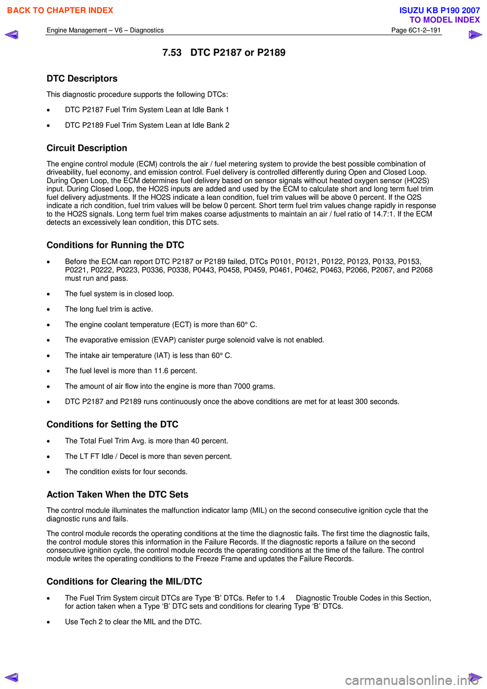
7.53 DTC P2187 or P2189
DTC Descriptors
This diagnostic procedure supports the following DTCs:
• DTC P2187 Fuel Trim System Lean at Idle Bank 1
• DTC P2189 Fuel Trim System Lean at Idle Bank 2
Circuit Description
The engine control module (ECM) controls the air / fuel metering system to provide the best possible combination of
driveability, fuel economy, and emission control. Fuel delivery is controlled differently during Open and Closed Loop.
During Open Loop, the ECM determines fuel delivery based on sensor signals without heated oxygen sensor (HO2S)
input. During Closed Loop, the HO2S inputs are added and used by the ECM to calculate short and long term fuel trim
fuel delivery adjustments. If the HO2S indicate a lean condition, fuel trim values will be above 0 percent. If the O2S
indicate a rich condition, fuel trim values will be below 0 percent. Short term fuel trim values change rapidly in response
to the HO2S signals. Long term fuel trim makes coarse adjustments to maintain an air / fuel ratio of 14.7:1. If the ECM
detects an excessively lean condition, this DTC sets.
Conditions for Running the DTC
• Before the ECM can report DTC P2187 or P2189 failed, DTCs P0101, P0121, P0122, P0123, P0133, P0153,
P0221, P0222, P0223, P0336, P0338, P0443, P0458, P0459, P0461, P0462, P0463, P2066, P2067, and P2068
must run and pass.
• The fuel system is in closed loop.
• The long fuel trim is active.
• The engine coolant temperature (ECT) is more than 60° C.
• The evaporative emission (EVAP) canister purge solenoid valve is not enabled.
• The intake air temperature (IAT) is less than 60° C.
• The fuel level is more than 11.6 percent.
• The amount of air flow into the engine is more than 7000 grams.
• DTC P2187 and P2189 runs continuously once the above conditions are met for at least 300 seconds.
Conditions for Setting the DTC
• The Total Fuel Trim Avg. is more than 40 percent.
• The LT FT Idle / Decel is more than seven percent.
• The condition exists for four seconds.
Action Taken When the DTC Sets
The control module illuminates the malfunction indicator lamp (MIL) on the second consecutive ignition cycle that the
diagnostic runs and fails.
The control module records the operating conditions at the time the diagnostic fails. The first time the diagnostic fails,
the control module stores this information in the Failure Records. If the diagnostic reports a failure on the second
consecutive ignition cycle, the control module records the operating conditions at the time of the failure. The control
module writes the operating conditions to the Freeze Frame and updates the Failure Records.
Conditions for Clearing the MIL/DTC
• The Fuel Trim System circuit DTCs are Type ‘B’ DTCs. Refer to 1.4 Diagnostic Trouble Codes in this Section,
for action taken when a Type ‘B’ DTC sets and conditions for clearing Type ‘B’ DTCs.
• Use Tech 2 to clear the MIL and the DTC.
BACK TO CHAPTER INDEX
TO MODEL INDEX
ISUZU KB P190 2007
Page 3472 of 6020
Engine Management – V6 – Diagnostics Page 6C1-2–194
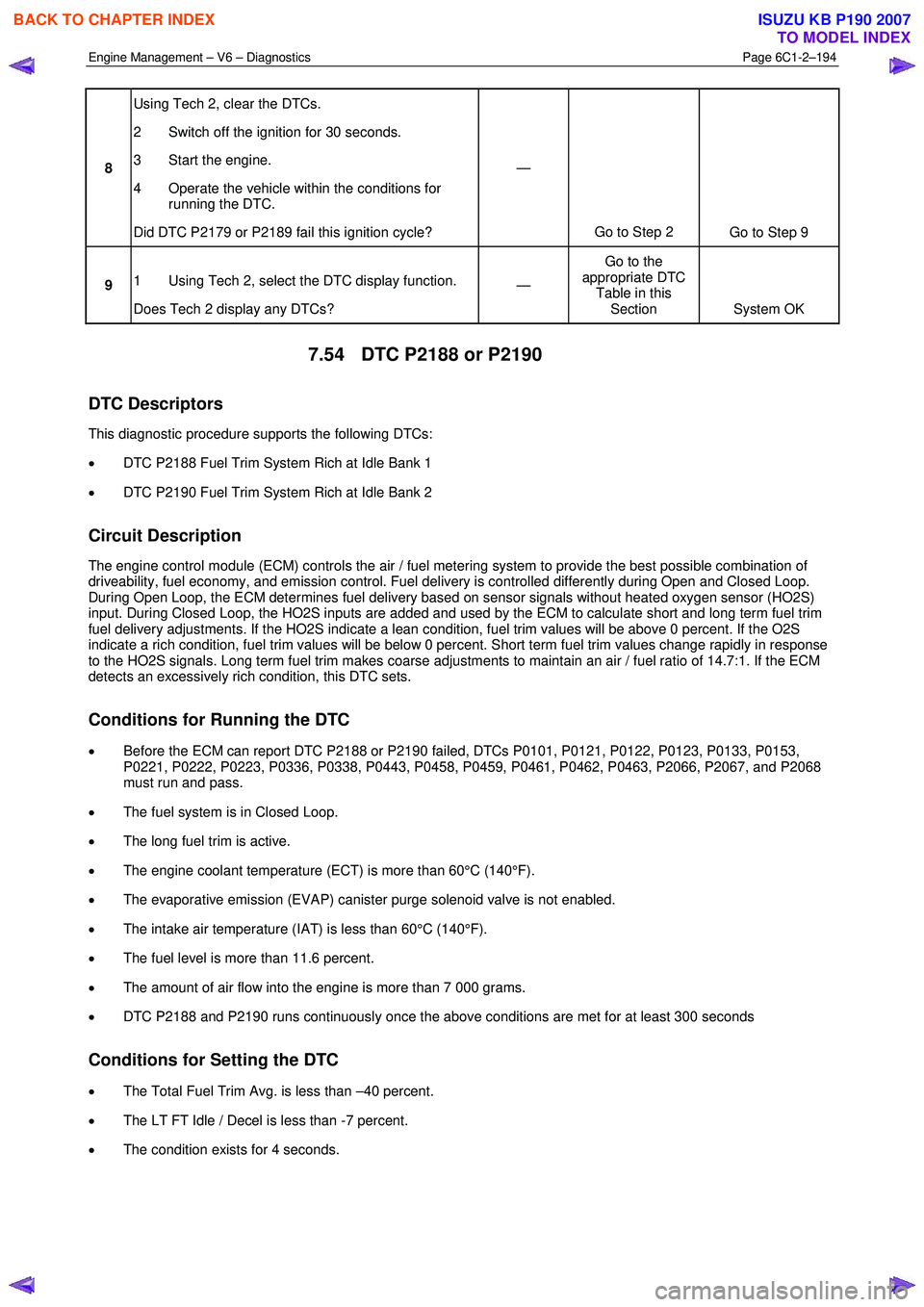
8 Using Tech 2, clear the DTCs.
2 Switch off the ignition for 30 seconds.
3 Start the engine.
4 Operate the vehicle within the conditions for running the DTC.
Did DTC P2179 or P2189 fail this ignition cycle? —
Go to Step 2 Go to Step 9
9 1 Using Tech 2, select the DTC display function.
Does Tech 2 display any DTCs? —
Go to the
appropriate DTC Table in this Section System OK
7.54 DTC P2188 or P2190
DTC Descriptors
This diagnostic procedure supports the following DTCs:
• DTC P2188 Fuel Trim System Rich at Idle Bank 1
• DTC P2190 Fuel Trim System Rich at Idle Bank 2
Circuit Description
The engine control module (ECM) controls the air / fuel metering system to provide the best possible combination of
driveability, fuel economy, and emission control. Fuel delivery is controlled differently during Open and Closed Loop.
During Open Loop, the ECM determines fuel delivery based on sensor signals without heated oxygen sensor (HO2S)
input. During Closed Loop, the HO2S inputs are added and used by the ECM to calculate short and long term fuel trim
fuel delivery adjustments. If the HO2S indicate a lean condition, fuel trim values will be above 0 percent. If the O2S
indicate a rich condition, fuel trim values will be below 0 percent. Short term fuel trim values change rapidly in response
to the HO2S signals. Long term fuel trim makes coarse adjustments to maintain an air / fuel ratio of 14.7:1. If the ECM
detects an excessively rich condition, this DTC sets.
Conditions for Running the DTC
• Before the ECM can report DTC P2188 or P2190 failed, DTCs P0101, P0121, P0122, P0123, P0133, P0153,
P0221, P0222, P0223, P0336, P0338, P0443, P0458, P0459, P0461, P0462, P0463, P2066, P2067, and P2068
must run and pass.
• The fuel system is in Closed Loop.
• The long fuel trim is active.
• The engine coolant temperature (ECT) is more than 60°C (140°F).
• The evaporative emission (EVAP) canister purge solenoid valve is not enabled.
• The intake air temperature (IAT) is less than 60°C (140°F).
• The fuel level is more than 11.6 percent.
• The amount of air flow into the engine is more than 7 000 grams.
• DTC P2188 and P2190 runs continuously once the above conditions are met for at least 300 seconds
Conditions for Setting the DTC
• The Total Fuel Trim Avg. is less than –40 percent.
• The LT FT Idle / Decel is less than -7 percent.
• The condition exists for 4 seconds.
BACK TO CHAPTER INDEX
TO MODEL INDEX
ISUZU KB P190 2007
Page 3519 of 6020
Engine Management – V6 – Diagnostics Page 6C1-2–241
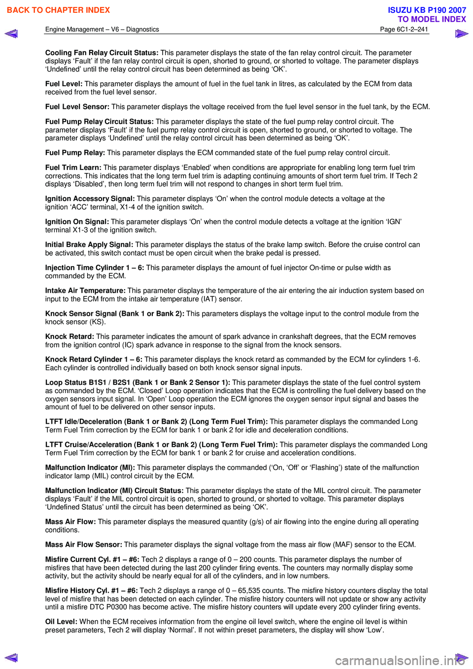
Cooling Fan Relay Circuit Status: This parameter displays the state of the fan relay control circuit. The parameter
displays ‘Fault’ if the fan relay control circuit is open, shorted to ground, or shorted to voltage. The parameter displays
‘Undefined’ until the relay control circuit has been determined as being ‘OK’.
Fuel Level: This parameter displays the amount of fuel in the fuel tank in litres, as calculated by the ECM from data
received from the fuel level sensor.
Fuel Level Sensor: This parameter displays the voltage received from the fuel level sensor in the fuel tank, by the ECM.
Fuel Pump Relay Circuit Status: This parameter displays the state of the fuel pump relay control circuit. The
parameter displays ‘Fault’ if the fuel pump relay control circuit is open, shorted to ground, or shorted to voltage. The
parameter displays ‘Undefined’ until the relay control circuit has been determined as being ‘OK’.
Fuel Pump Relay: This parameter displays the ECM commanded state of the fuel pump relay control circuit.
Fuel Trim Learn: This parameter displays ‘Enabled’ when conditions are appropriate for enabling long term fuel trim
corrections. This indicates that the long term fuel trim is adapting continuing amounts of short term fuel trim. If Tech 2
displays ‘Disabled’, then long term fuel trim will not respond to changes in short term fuel trim.
Ignition Accessory Signal: This parameter displays ‘On’ when the control module detects a voltage at the
ignition ‘ACC’ terminal, X1-4 of the ignition switch.
Ignition On Signal: This parameter displays ‘On’ when the control module detects a voltage at the ignition ‘IGN’
terminal X1-3 of the ignition switch.
Initial Brake Apply Signal: This parameter displays the status of the brake lamp switch. Before the cruise control can
be activated, this switch contact must be open circuit when the brake pedal is pressed.
Injection Time Cylinder 1 – 6: This parameter displays the amount of fuel injector On-time or pulse width as
commanded by the ECM.
Intake Air Temperature: This parameter displays the temperature of the air entering the air induction system based on
input to the ECM from the intake air temperature (IAT) sensor.
Knock Sensor Signal (Bank 1 or Bank 2): This parameters displays the voltage input to the control module from the
knock sensor (KS).
Knock Retard: This parameter indicates the amount of spark advance in crankshaft degrees, that the ECM removes
from the ignition control (IC) spark advance in response to the signal from the knock sensors.
Knock Retard Cylinder 1 – 6: This parameter displays the knock retard as commanded by the ECM for cylinders 1-6.
Each cylinder is controlled individually based on both knock sensor signal inputs.
Loop Status B1S1 / B2S1 (Bank 1 or Bank 2 Sensor 1): This parameter displays the state of the fuel control system
as commanded by the ECM. ‘Closed’ Loop operation indicates that the ECM is controlling the fuel delivery based on the
oxygen sensors input signal. In ‘Open’ Loop operation the ECM ignores the oxygen sensor input signal and bases the
amount of fuel to be delivered on other sensor inputs.
LTFT Idle/Deceleration (Bank 1 or Bank 2) (Long Term Fuel Trim): This parameter displays the commanded Long
Term Fuel Trim correction by the ECM for bank 1 or bank 2 for idle and deceleration conditions.
LTFT Cruise/Acceleration (Bank 1 or Bank 2) (Long Term Fuel Trim): This parameter displays the commanded Long
Term Fuel Trim correction by the ECM for bank 1 or bank 2 for cruise and acceleration conditions.
Malfunction Indicator (MI): This parameter displays the commanded (‘On, ‘Off’ or ‘Flashing’) state of the malfunction
indicator lamp (MIL) control circuit by the ECM.
Malfunction Indicator (MI) Circuit Status: This parameter displays the state of the MIL control circuit. The parameter
displays ‘Fault’ if the MIL control circuit is open, shorted to ground, or shorted to voltage. This parameter displays
‘Undefined Status’ until the circuit has been determined as being ‘OK’.
Mass Air Flow: This parameter displays the measured quantity (g/s) of air flowing into the engine during all operating
conditions.
Mass Air Flow Sensor: This parameter displays the signal voltage from the mass air flow (MAF) sensor to the ECM.
Misfire Current Cyl. #1 – #6: Tech 2 displays a range of 0 – 200 counts. This parameter displays the number of
misfires that have been detected during the last 200 cylinder firing events. The counters may normally display some
activity, but the activity should be nearly equal for all of the cylinders, and in low numbers.
Misfire History Cyl. #1 – #6: Tech 2 displays a range of 0 – 65,535 counts. The misfire history counters display the total
level of misfire that has been detected on each cylinder. The misfire history counters will not update or show any activity
until a misfire DTC P0300 has become active. The misfire history counters will update every 200 cylinder firing events.
Oil Level: W hen the ECM receives information from the engine oil level switch, where the engine oil level is within
preset parameters, Tech 2 will display ‘Normal’. If not within preset parameters, the display will show ‘Low’.
BACK TO CHAPTER INDEX
TO MODEL INDEX
ISUZU KB P190 2007
Page 3520 of 6020
Engine Management – V6 – Diagnostics Page 6C1-2–242
Oil Temperature Sensor: This parameter displays the engine oil temperature in degrees C.
Power Enrichment: This parameter displays the status of the operating mode of the ECM used to increase fuel delivery
during certain acceleration conditions.
Reduced Engine Power: This parameter displays when the ECM is commanding reduced engine power due to a
throttle actuator control (TAC) system condition.
Requested Torque: This parameter displays the calculated amount torque requested of the ECM by the Transmission
Control Module (TCM).
Short Term Fuel Trim (Bank 1 or Bank 2): This parameter displays the short-term correction to the fuel delivery by the
ECM in response to oxygen sensor 1 or 2. If the oxygen sensor indicates a lean air/fuel mixture, the control module will
add fuel, increasing the short term fuel trim above 0. If the oxygen sensor indicates a rich air/fuel mixture, the control
module will reduce fuel decreasing the short term fuel trim below 0.
Spark Advance: This parameter displays the amount of spark advance the ECM is commanding on the ignition control
circuits. The ECM determines the desired advance.
Starter Relay: This parameter displays the Em’s commanded state of the starter motor relay control circuit.
Starter Relay Circuit Status: This parameter displays the state of the starter relay control circuit. The parameter
displays ‘Fault’ if the starter relay control circuit is open, shorted to ground, or shorted to voltage. The parameter
displays Undefined Status’ until the circuit has been determined as being ‘OK’. This parameter may not change if Tech 2
is used to command the relay control circuit ON.
Start Up ECT (Engine Coolant Temperature): This parameter displays the temperature of the engine coolant on start
up based on input to the ECM from the ECT sensor.
Start Up IAT (Intake Air Temperature): This parameter displays the temperature of the intake air at start in the air
induction system based on input to the ECM from the IAT sensor.
Time Since Engine Off: This parameter displays the amount of time (hours:minutes:seconds) that has elapsed since
the engine was last cycled OFF.
Total Fuel Trim (Bank 1 or Bank 2): This parameter displays the overall fuel trim from the idle/decel cell and the
cruise/accel cell.
Total Misfire: This parameter displays the total number of cylinder firing events that the control module detected as
misfires for the last 200 crankshaft revolution sample period.
TP Sensor 1 (Throttle Position): This parameter displays the actual voltage on the TP sensor 1 signal circuit as
measured by the ECM.
TP Sensor 1 Learned Lower Position (Throttle Position): This parameter displays the learned minimum value of TP
sensor 1 as recorded by the ECM during the last learn procedure.
TP Sensor 2 (Throttle Position): This parameter displays the actual voltage on the TP sensor 2 signal circuit as
measured by the ECM.
TP Sensor 2 Learned Lower Position (Throttle Position): This parameter displays the learned minimum value of TP
sensor 2 as recorded by the ECM during the last learn procedure.
TP Sensor 1-2 Correlation (Throttle Position): This parameter displays ‘Fault’ when the ECM detects that TP sensor 1
voltage signal is not within the correct relationship to TP sensor 2. Tech 2 displays ‘Okay’ under normal operating
conditions.
Transmission Gear: This parameter displays the position of the transmission gear selector that is transmitted over the
serial data circuit from the TCM.
Transmission Gear Selector Signal: This parameter displays the position of the transmission gear selector that is
transmitted over the serial data circuit from the TCM.
Vehicle Speed: This parameter displays the speed of the vehicle as calculated by the TCM from information received
from the vehicle speed sensor (VSS).
Volumetric Efficiency: This parameter displays the volumetric efficiency of the engine as calculated by the control
module.
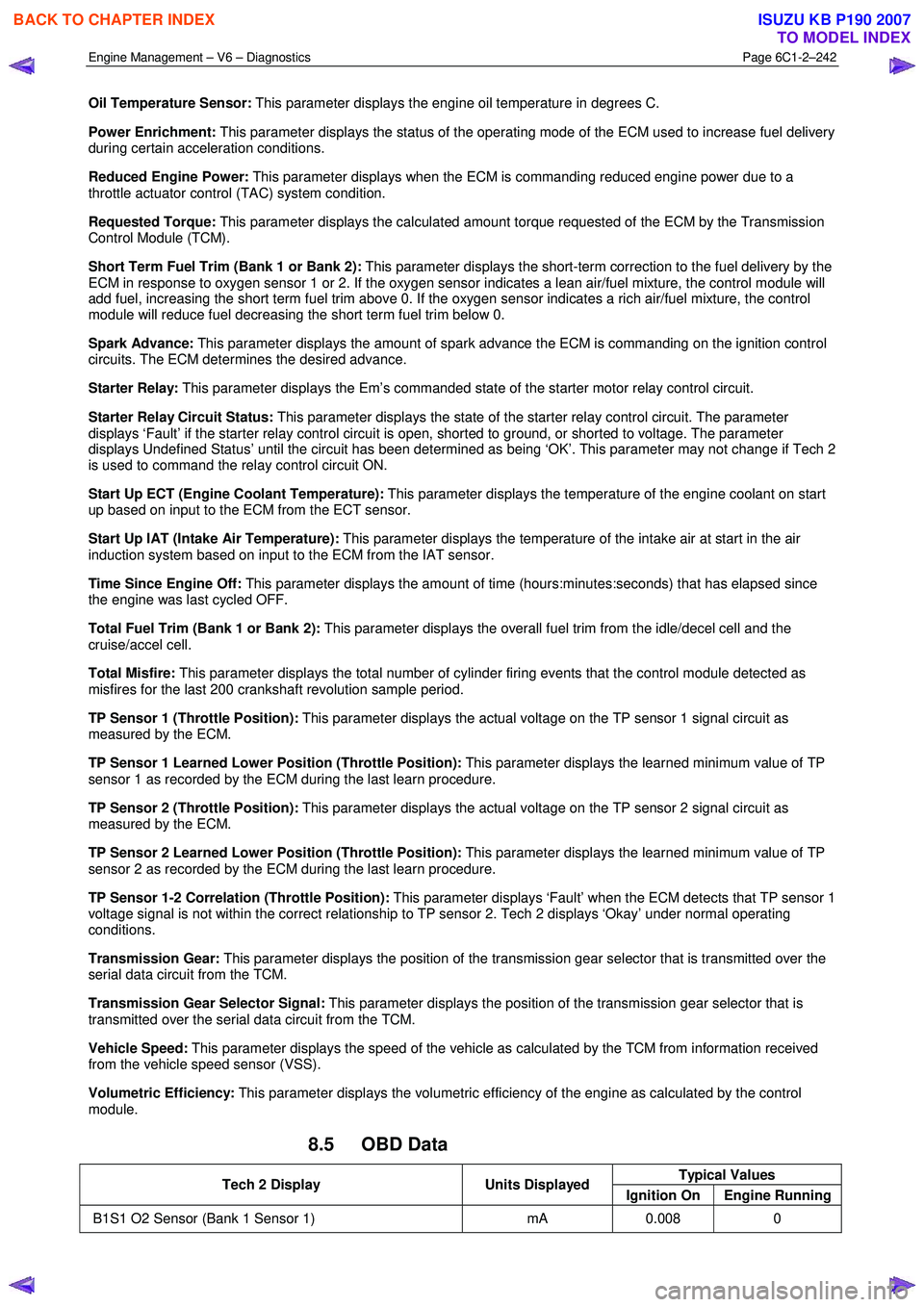
8.5 OBD Data
Typical Values Tech 2 Display Units Displayed
Ignition On Engine Running
B1S1 O2 Sensor (Bank 1 Sensor 1) mA 0.008 0
BACK TO CHAPTER INDEX
TO MODEL INDEX
ISUZU KB P190 2007