2007 ISUZU KB P190 ESP
[x] Cancel search: ESPPage 2392 of 6020

6E–222 ENGINE DRIVEABILITY AND EMISSIONS
DIAGNOSTIC TROUBLE CODE (DTC) P1631 IMMOBILIZER WRONG SIGNAL
Condition for setting the DTC and action taken when the DTC sets
Circuit Description
The ECM decides whether that is an abnomality in the
immobilizer control system. DTC P1631 is recorded by
the ECM when received response was not correct.
Diagnostic Aids
Check for the following conditions:
• Poor connection at ECM and Immobilizer-Inspect harness connectors for backed out terminals,
improper mating, broken locks, improperly formed or damaged terminals, and poor terminal to wire
connection.
• Damaged harness-Inspect the wiring harness for damage, If the harness appears to be OK, disconnect
the ECM and Immobilizer, turn the ignition “ON” and
observe a voltmeter connected to the suspect driver
circuit at the ECM and Immobilizer harnass connector
while moving connectors and wiring harnesses
relates to the MIL. A change in voltage will indicate
the location of the fault.
Code Type DTC Name DTC Setting Condition Fail-Safe (Back Up)
P1631 - Immobilizer Wrong Signal Received response is not correct.1. Engine does not start.
2. Check engine lamp flash.
BACK TO CHAPTER INDEX
TO MODEL INDEX
ISUZU KB P190 2007
Page 2412 of 6020

6E–242 ENGINE DRIVEABILITY AND EMISSIONS
SURGES AND/OR CHUGS SYMPTOM
DEFINITIONS: See the illustration below. Feels like the
vehicle speeds up and slows down with no charge in the
accelerator pedal.
Step Action Value(s) Yes No
1 Was the “ On-Board Diagnostic (OBD) System Check ”
performed? — Go to Step 2Go to
OBD
System Check
2 1. Perform a bulletin search. 2. If a bulletin that addresses the symptom is found,correct the condition as instructed in the bulletin.
Was a bulletin found that addresses the symptom? — Verify repair Go to Step 3
3 Was a visual/physical check performed? —Go to Step 4Go to
Visual /
physical Check.
4 Be sure that the driver understands A/C compressor operation as explained in the owner’s manual. Inform
the customer how the A/C clutch operate.
Is the customer experiencing a normal condition? — System OK Go to Step 5
5 1. Using a Tech 2, display the MAP sensor value in comparison with atmosphere temperature.
2. Check for a faulty, plugged, or incorrectly installed MAP sensor.
Was the problem found? — Verify repair Go to Step 6
6 Observe the throttle position display on the Tech 2 while slowly increasing throttle pedal.
Is the throttle position at the specified value and
steady in any position?
—Go to Step 7Refer to
Diagnostic
Trouble Code P0123 for further
diagnosis
7 Check the knock sensor wire, shield wire, or installation condition.
Was a problem found? — Verify repair Go to Step 8
8 Run Engine. Check the fuel control Heated Oxygen Sensor
(HO2S). When monitored on the Tech 2, the HO2S
should respond quickly to different throttle positions. If
it doesn’t check for silicon or other contaminates from
fuel or use of improper sealant. The sensors may
have a white powdery coating. Silicon contamination
sends a rich exhaust signal which causes the ECM to
command an excessively lean air/fuel mixture.
Was a problem found? — Verify repair Go to Step 9
BACK TO CHAPTER INDEX
TO MODEL INDEX
ISUZU KB P190 2007
Page 2415 of 6020
ENGINE DRIVEABILITY AND EMISSIONS 6E–245
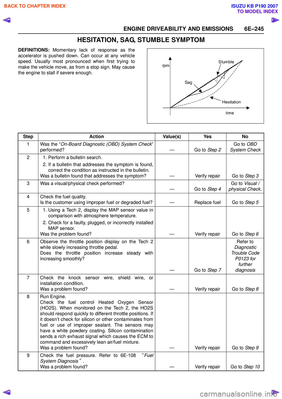
HESITATION, SAG, STUMBLE SYMPTOM
DEFINITIONS: Momentary lack of response as the
accelerator is pushed down. Can occur at any vehicle
speed. Usually most pronounced when first trying to
make the vehicle move, as from a stop sign. May cause
the engine to stall if severe enough.
Step Action Value(s) Yes No
1 Was the “ On-Board Diagnostic (OBD) System Check ”
performed? — Go to Step 2Go to
OBD
System Check
2 1. Perform a bulletin search. 2. If a bulletin that addresses the symptom is found,correct the condition as instructed in the bulletin.
Was a bulletin found that addresses the symptom? — Verify repair Go to Step 3
3 Was a visual/physical check performed? —Go to Step 4Go to
Visual /
physical Check .
4 Check the fuel quality. Is the customer using improper fuel or degraded fuel? — Replace fuel Go to Step 5
5 1. Using a Tech 2, display the MAP sensor value in comparison with atmosphere temperature.
2. Check for a faulty, plugged, or incorrectly installed MAP sensor.
Was the problem found? — Verify repair Go to Step 6
6 Observe the throttle position display on the Tech 2 while slowly increasing throttle pedal.
Does the throttle position increase steady with
increasing smoothly?
—Go to Step 7Refer to
Diagnostic
Trouble Code P0123 for further
diagnosis
7 Check the knock sensor wire, shield wire, or installation condition.
Was a problem found? — Verify repair Go to Step 8
8 Run Engine. Check the fuel control Heated Oxygen Sensor
(HO2S). When monitored on the Tech 2, the HO2S
should respond quickly to different throttle positions. If
it doesn’t check for silicon or other contaminates from
fuel or use of improper sealant. The sensors may
have a white powdery coating. Silicon contamination
sends a rich exhaust signal which causes the ECM to
command and excessively lean air/fuel mixture.
Was a problem found? — Verify repair Go to Step 9
9 Check the fuel pressure. Refer to 6E-108 “Fuel
System Diagnosis
”.
Was a problem found? — Verify repair Go to Step 10
BACK TO CHAPTER INDEX
TO MODEL INDEX
ISUZU KB P190 2007
Page 2421 of 6020
ENGINE DRIVEABILITY AND EMISSIONS 6E–251
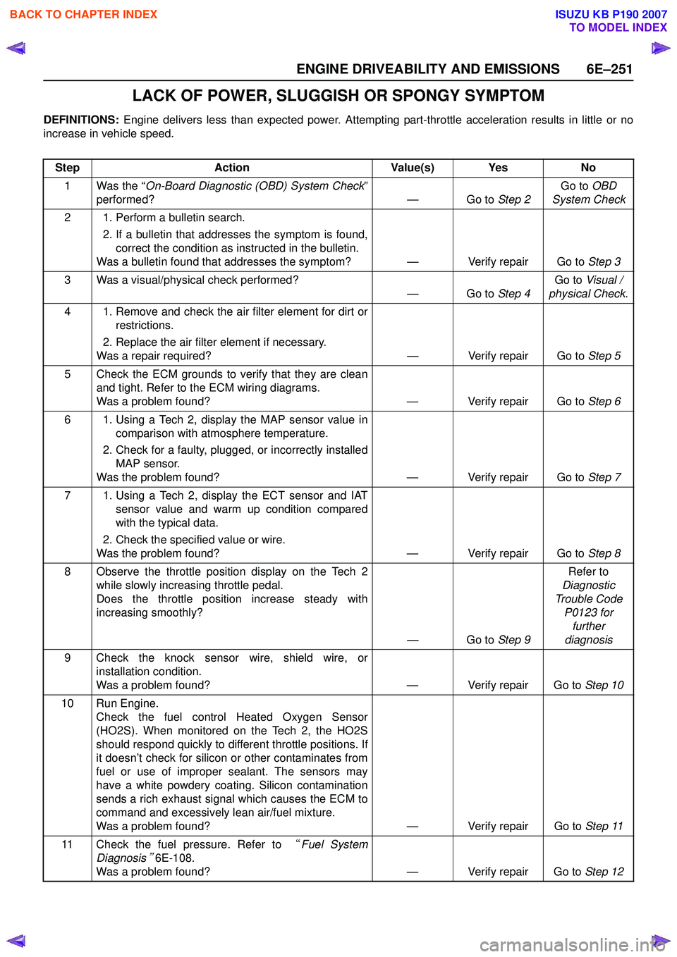
LACK OF POWER, SLUGGISH OR SPONGY SYMPTOM
DEFINITIONS: Engine delivers less than expected power. Attempting part-throttle acceleration results in little or no
increase in vehicle speed.
Step Action Value(s) Yes No
1 Was the “ On-Board Diagnostic (OBD) System Check ”
performed? — Go to Step 2Go to
OBD
System Check
2 1. Perform a bulletin search. 2. If a bulletin that addresses the symptom is found,correct the condition as instructed in the bulletin.
Was a bulletin found that addresses the symptom? — Verify repair Go to Step 3
3 Was a visual/physical check performed? —Go to Step 4Go to
Visual /
physical Check .
4 1. Remove and check the air filter element for dirt or restrictions.
2. Replace the air filter element if necessary.
Was a repair required? — Verify repair Go to Step 5
5 Check the ECM grounds to verify that they are clean and tight. Refer to the ECM wiring diagrams.
Was a problem found? — Verify repair Go to Step 6
6 1. Using a Tech 2, display the MAP sensor value in comparison with atmosphere temperature.
2. Check for a faulty, plugged, or incorrectly installed MAP sensor.
Was the problem found? — Verify repair Go to Step 7
7 1. Using a Tech 2, display the ECT sensor and IAT sensor value and warm up condition compared
with the typical data.
2. Check the specified value or wire.
Was the problem found? — Verify repair Go to Step 8
8 Observe the throttle position display on the Tech 2 while slowly increasing throttle pedal.
Does the throttle position increase steady with
increasing smoothly?
—Go to Step 9Refer to
Diagnostic
Trouble Code P0123 for further
diagnosis
9 Check the knock sensor wire, shield wire, or installation condition.
Was a problem found? — Verify repair Go to Step 10
10 Run Engine. Check the fuel control Heated Oxygen Sensor
(HO2S). When monitored on the Tech 2, the HO2S
should respond quickly to different throttle positions. If
it doesn’t check for silicon or other contaminates from
fuel or use of improper sealant. The sensors may
have a white powdery coating. Silicon contamination
sends a rich exhaust signal which causes the ECM to
command and excessively lean air/fuel mixture.
Was a problem found? — Verify repair Go to Step 11
11 Check the fuel pressure. Refer to “Fuel System
Diagnosis
” 6E-108.
Was a problem found? — Verify repair Go to Step 12
BACK TO CHAPTER INDEX
TO MODEL INDEX
ISUZU KB P190 2007
Page 2429 of 6020
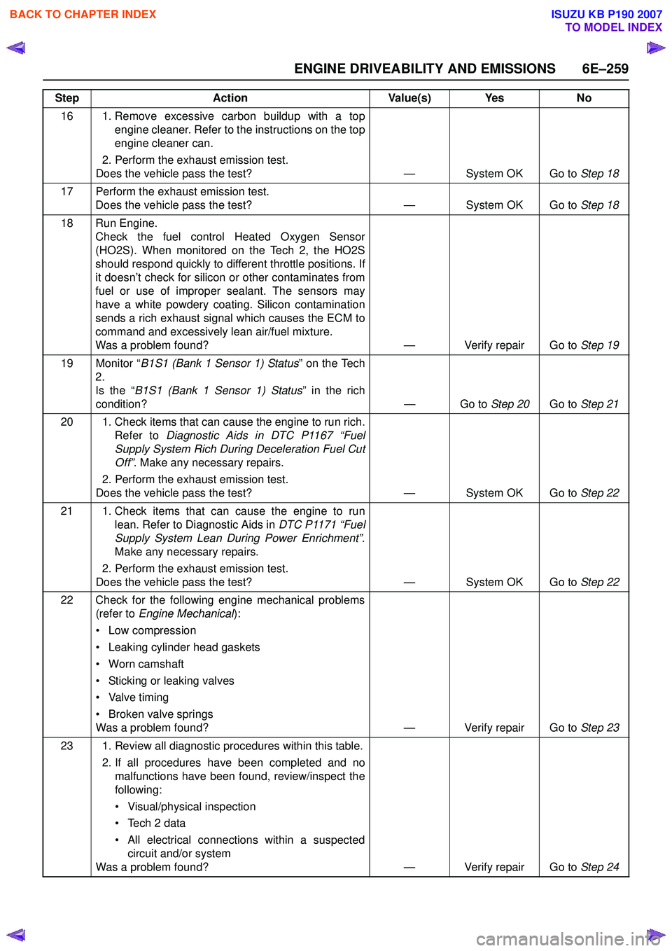
ENGINE DRIVEABILITY AND EMISSIONS 6E–259
16 1. Remove excessive carbon buildup with a topengine cleaner. Refer to the instructions on the top
engine cleaner can.
2. Perform the exhaust emission test.
Does the vehicle pass the test? — System OK Go to Step 18
17 Perform the exhaust emission test. Does the vehicle pass the test? — System OK Go to Step 18
18 Run Engine. Check the fuel control Heated Oxygen Sensor
(HO2S). When monitored on the Tech 2, the HO2S
should respond quickly to different throttle positions. If
it doesn’t check for silicon or other contaminates from
fuel or use of improper sealant. The sensors may
have a white powdery coating. Silicon contamination
sends a rich exhaust signal which causes the ECM to
command and excessively lean air/fuel mixture.
Was a problem found? — Verify repair Go to Step 19
19 Monitor “ B1S1 (Bank 1 Sensor 1) Status ” on the Tech
2.
Is the “ B1S1 (Bank 1 Sensor 1) Status ” in the rich
condition? — Go to Step 20Go to Step 21
20 1. Check items that can cause the engine to run rich. Refer to Diagnostic Aids in DTC P1167 “Fuel
Supply System Rich During Deceleration Fuel Cut
Off” . Make any necessary repairs.
2. Perform the exhaust emission test.
Does the vehicle pass the test? — System OK Go to Step 22
21 1. Check items that can cause the engine to run lean. Refer to Diagnostic Aids in DTC P1171 “Fuel
Supply System Lean During Power Enrichment” .
Make any necessary repairs.
2. Perform the exhaust emission test.
Does the vehicle pass the test? — System OK Go to Step 22
22 Check for the following engine mechanical problems (refer to Engine Mechanical ):
• Low compression
• Leaking cylinder head gaskets
• Worn camshaft
• Sticking or leaking valves
• Valve timing
• Broken valve springs
Was a problem found? — Verify repair Go to Step 23
23 1. Review all diagnostic procedures within this table. 2. If all procedures have been completed and nomalfunctions have been found, review/inspect the
following:
• Visual/physical inspection
• Tech 2 data
• All electrical connections within a suspected circuit and/or system
Was a problem found? — Verify repair Go to Step 24
Step
Action Value(s) Yes No
BACK TO CHAPTER INDEX
TO MODEL INDEX
ISUZU KB P190 2007
Page 2501 of 6020

Engine Mechanical – V6 Page 6A1–22
Crankshaft
The crankshaft is a forged steel design with four main bearings. The number three main bearing controls crankshaft
thrust. A crankshaft position reluctor wheel is pressed onto the rear of the crankshaft, in front of the rear main journal.
The crankshaft is internally balanced with an integral oil pump drive machined into the nose in front of the front main
journal.
Pistons, Pins and Connecting Rods
The piston assembly (1) is fitted with two low tension
compression rings and one multi-piece oil control ring. The
top compression ring is plasma sprayed, while the second
compression ring is cast iron Napier.
The oil control ring incorporates a steel expander and two
chrome plated steel rails.
The connecting rods are sinter forged steel and have full
floating piston pins. The piston pins are a slip-fit type, into
the bronze bushed connecting rods. Round wire retainers
are used to retain the piston pin into the piston.
The cast aluminium pistons incorporate a polymer coated
skirt to reduce friction.
Figure 6A1 – 17
Camshaft Drive System
Three timing chains are fitted:
• primary (1),
• right-hand secondary (2), and
• left-hand secondary (3), refer to Figure 6A1 – 18 for the HFV6 engine.
The primary timing chain connects the crankshaft sprocket (4) with the left-hand and right-hand intermediate drive shaft
sprockets (5).
Each oil pressure fed intermediate sprocket drives the secondary timing chains, which subsequently drive the respective
cylinder head camshaft position actuators (6).
Two stationary timing chain guides (7) and movable timing chain shoes (8) control secondary timing chain backlash.
Each secondary timing chain shoe is under tension from an oil pressure hydraulically operated tensioner (9). To control
backlash on the primary chain, two stationary timing chain guides (10) and an oil pressure hydraulically actuated
tensioner with built in shoe (11) are fitted.
The tensioners minimise timing chain noise and provide accurate valve action by keeping slack out of the timing chains,
while continuously adjusting for timing chain wear. The tensioners incorporate a plunger that adjusts outward with wear,
minimising backlash. The tensioners are equipped with oiling jets to spray oil onto the timing components during engine
operation. Each tensioner is sealed to the head or block using a rubber coated steel gasket. The gasket traps an
adequate oil reserve to ensure quiet start-up.
BACK TO CHAPTER INDEX
TO MODEL INDEX
ISUZU KB P190 2007
Page 2622 of 6020
Engine Mechanical – V6 Page 6A1–143
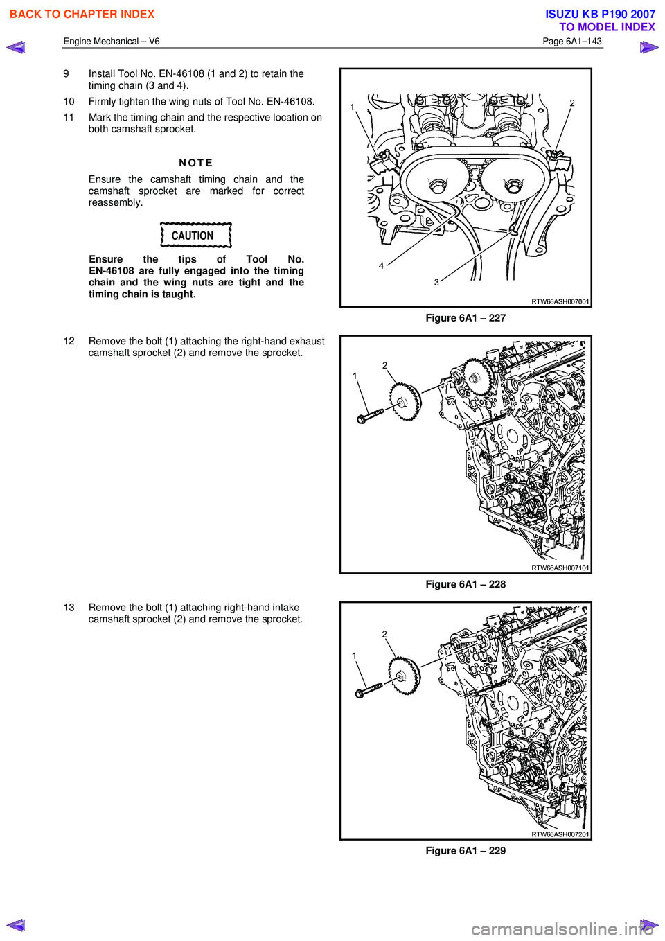
9 Install Tool No. EN-46108 (1 and 2) to retain the
timing chain (3 and 4).
10 Firmly tighten the wing nuts of Tool No. EN-46108.
11 Mark the timing chain and the respective location on both camshaft sprocket.
NOTE
Ensure the camshaft timing chain and the
camshaft sprocket are marked for correct
reassembly.
CAUTION
Ensure the tips of Tool No.
EN-46108 are fully engaged into the timing
chain and the wing nuts are tight and the
timing chain is taught.
Figure 6A1 – 227
12 Remove the bolt (1) attaching the right-hand exhaust camshaft sprocket (2) and remove the sprocket.
Figure 6A1 – 228
13 Remove the bolt (1) attaching right-hand intake camshaft sprocket (2) and remove the sprocket.
Figure 6A1 – 229
BACK TO CHAPTER INDEX
TO MODEL INDEX
ISUZU KB P190 2007
Page 2624 of 6020
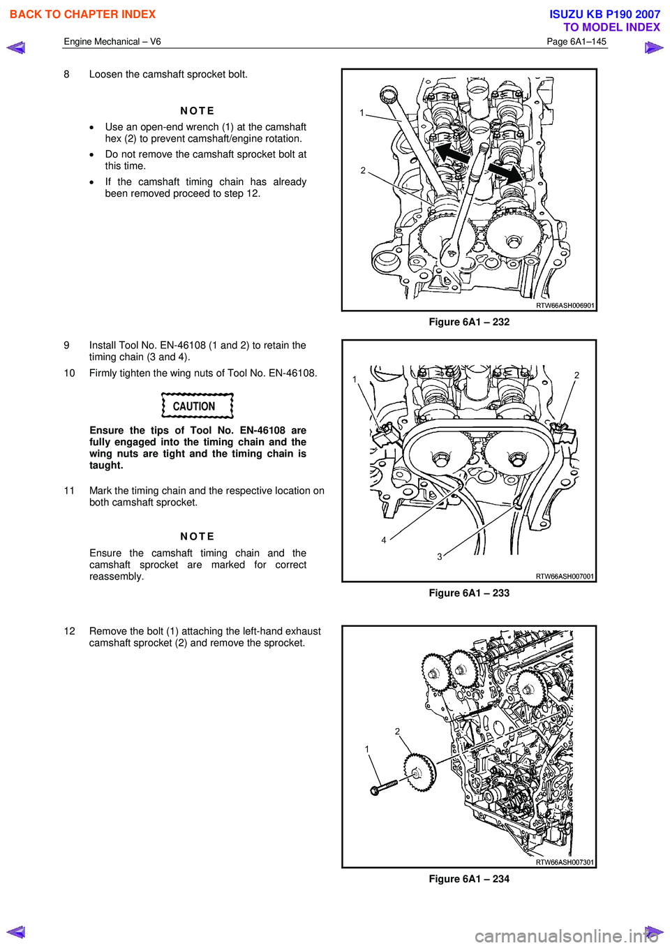
Engine Mechanical – V6 Page 6A1–145
8 Loosen the camshaft sprocket bolt.
NOTE
• Use an open-end wrench (1) at the camshaft
hex (2) to prevent camshaft/engine rotation.
• Do not remove the camshaft sprocket bolt at
this time.
• If the camshaft timing chain has already
been removed proceed to step 12.
Figure 6A1 – 232
9 Install Tool No. EN-46108 (1 and 2) to retain the timing chain (3 and 4).
10 Firmly tighten the wing nuts of Tool No. EN-46108.
CAUTION
Ensure the tips of Tool No. EN-46108 are
fully engaged into the timing chain and the
wing nuts are tight and the timing chain is
taught.
11 Mark the timing chain and the respective location on both camshaft sprocket.
NOTE
Ensure the camshaft timing chain and the
camshaft sprocket are marked for correct
reassembly.
Figure 6A1 – 233
12 Remove the bolt (1) attaching the left-hand exhaust camshaft sprocket (2) and remove the sprocket.
Figure 6A1 – 234
BACK TO CHAPTER INDEX
TO MODEL INDEX
ISUZU KB P190 2007