2007 ISUZU KB P190 ESP
[x] Cancel search: ESPPage 2073 of 6020
ENGINE MECHANICAL (C24SE) 6A-59
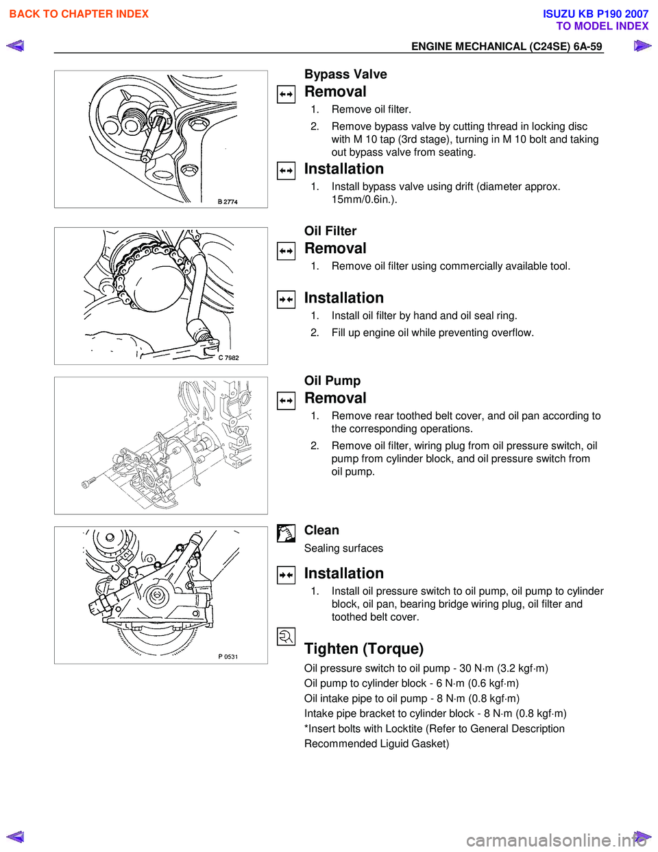
Bypass Valve
Removal
1. Remove oil filter.
2. Remove bypass valve by cutting thread in locking disc with M 10 tap (3rd stage), turning in M 10 bolt and taking
out bypass valve from seating.
Installation
1. Install bypass valve using drift (diameter approx. 15mm/0.6in.).
Oil Filter
Removal
1. Remove oil filter using commercially available tool.
Installation
1. Install oil filter by hand and oil seal ring.
2. Fill up engine oil while preventing overflow.
Oil Pump
Removal
1. Remove rear toothed belt cover, and oil pan according to the corresponding operations.
2. Remove oil filter, wiring plug from oil pressure switch, oil pump from cylinder block, and oil pressure switch from
oil pump.
Clean
Sealing surfaces
Installation
1. Install oil pressure switch to oil pump, oil pump to cylinder
block, oil pan, bearing bridge wiring plug, oil filter and
toothed belt cover.
Tighten (Torque)
Oil pressure switch to oil pump - 30 N ⋅m (3.2 kgf ⋅m)
Oil pump to cylinder block - 6 N ⋅m (0.6 kgf ⋅m)
Oil intake pipe to oil pump - 8 N ⋅m (0.8 kgf ⋅m)
Intake pipe bracket to cylinder block - 8 N ⋅m (0.8 kgf ⋅m)
*Insert bolts with Locktite (Refer to General Description
Recommended Liguid Gasket)
BACK TO CHAPTER INDEX
TO MODEL INDEX
ISUZU KB P190 2007
Page 2074 of 6020
6A-60 ENGINE MECHANICAL (C24SE)
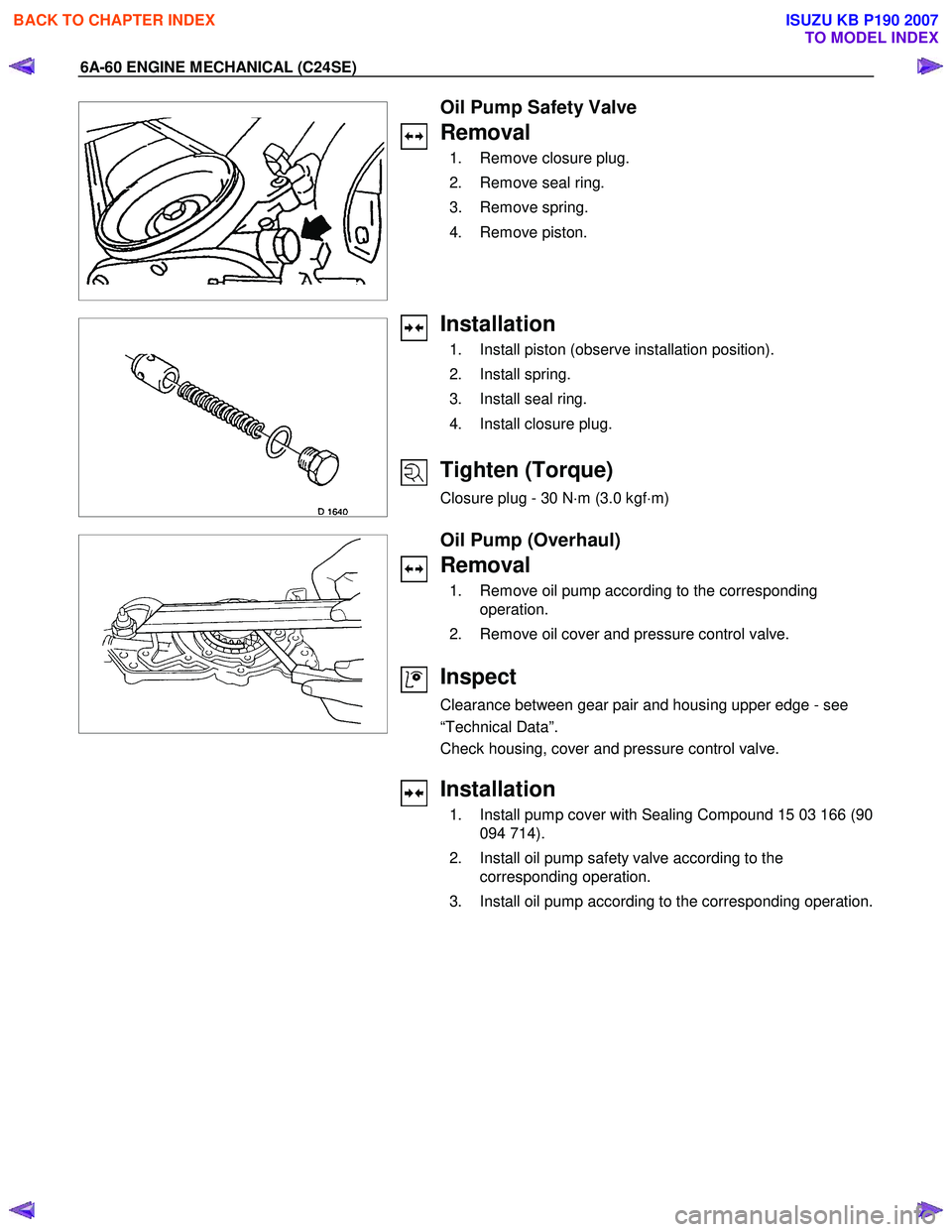
Oil Pump Safety Valve
Removal
1. Remove closure plug.
2. Remove seal ring.
3. Remove spring.
4. Remove piston.
Installation
1. Install piston (observe installation position).
2. Install spring.
3. Install seal ring.
4. Install closure plug.
Tighten (Torque)
Closure plug - 30 N ⋅m (3.0 kgf ⋅m)
Oil Pump (Overhaul)
Removal
1. Remove oil pump according to the corresponding operation.
2. Remove oil cover and pressure control valve.
Inspect
Clearance between gear pair and housing upper edge - see
“Technical Data”.
Check housing, cover and pressure control valve.
Installation
1. Install pump cover with Sealing Compound 15 03 166 (90 094 714).
2. Install oil pump safety valve according to the corresponding operation.
3. Install oil pump according to the corresponding operation.
BACK TO CHAPTER INDEX
TO MODEL INDEX
ISUZU KB P190 2007
Page 2075 of 6020
ENGINE MECHANICAL (C24SE) 6A-61
OPERATIONS ON OIL CIRCULATION
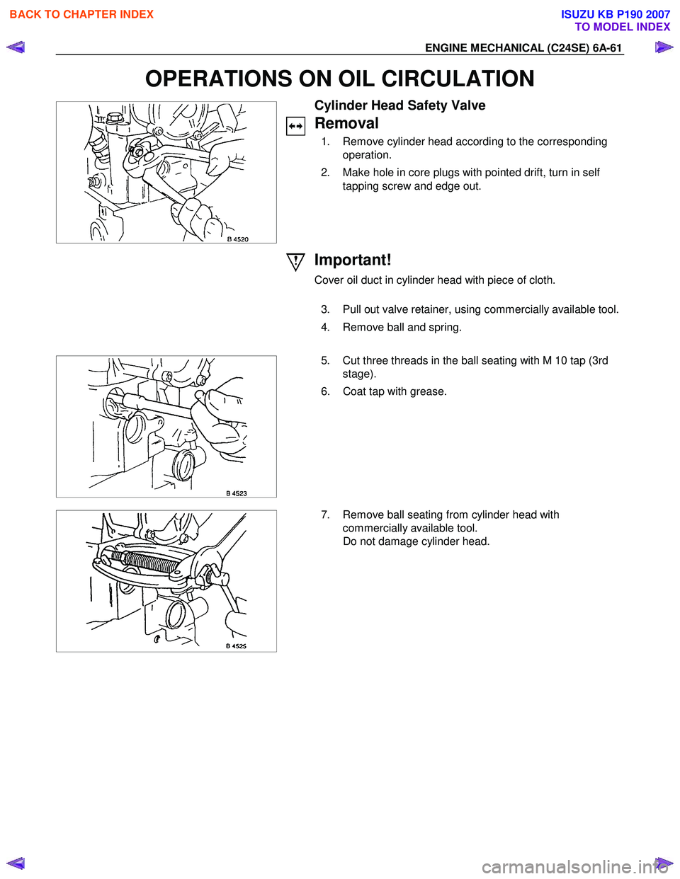
Cylinder Head Safety Valve
Removal
1. Remove cylinder head according to the corresponding operation.
2. Make hole in core plugs with pointed drift, turn in self tapping screw and edge out.
Important!
Cover oil duct in cylinder head with piece of cloth.
3. Pull out valve retainer, using commercially available tool.
4. Remove ball and spring.
5. Cut three threads in the ball seating with M 10 tap (3rd
stage).
6. Coat tap with grease.
7. Remove ball seating from cylinder head with
commercially available tool.
Do not damage cylinder head.
BACK TO CHAPTER INDEX
TO MODEL INDEX
ISUZU KB P190 2007
Page 2080 of 6020
6A-66 ENGINE MECHANICAL (C24SE)
Installation
Follow the removal procedure in the reverse order to install the
radiator.
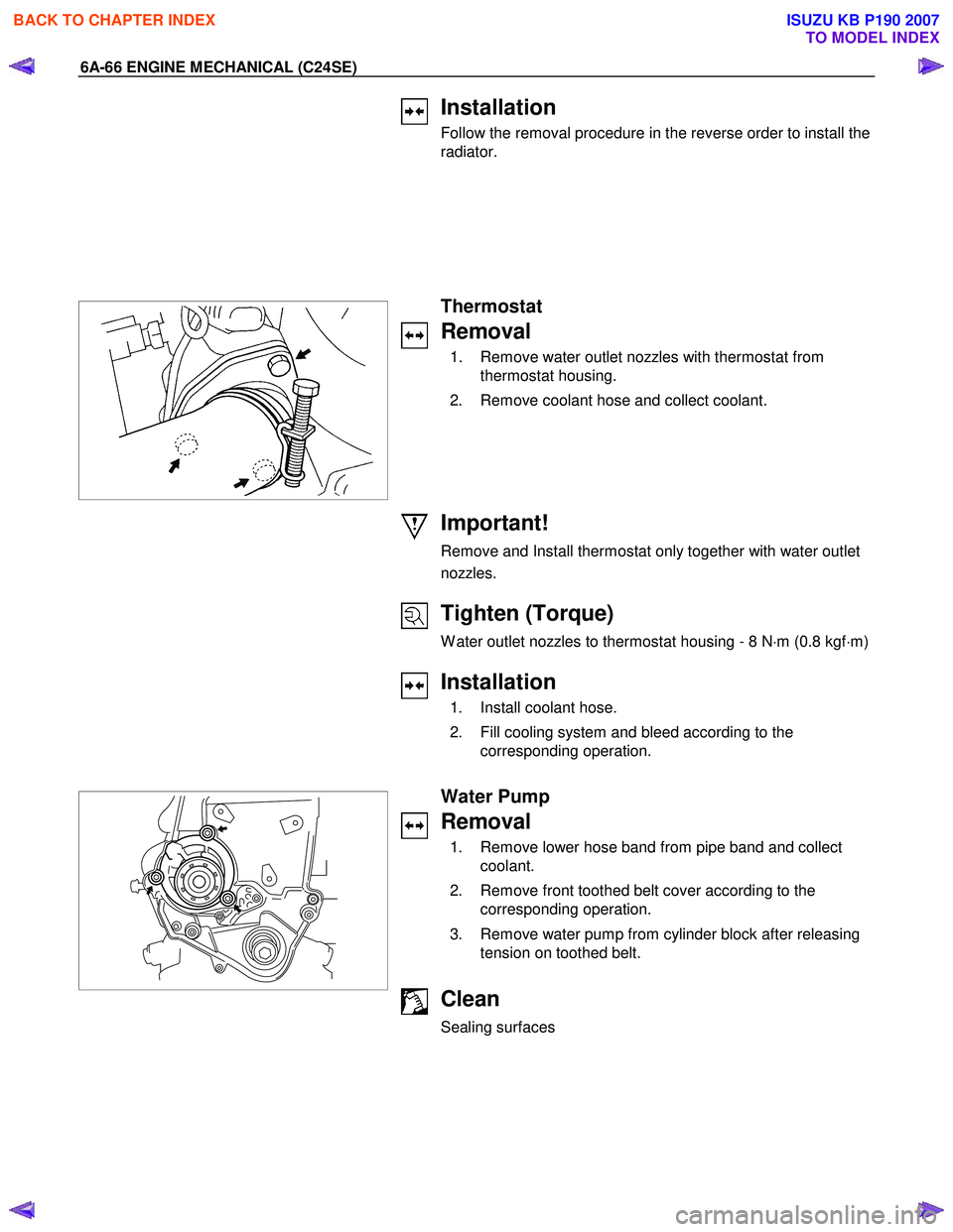
Thermostat
Removal
1. Remove water outlet nozzles with thermostat from thermostat housing.
2. Remove coolant hose and collect coolant.
Important!
Remove and Install thermostat only together with water outlet
nozzles.
Tighten (Torque)
W ater outlet nozzles to thermostat housing - 8 N ⋅m (0.8 kgf ⋅m)
Installation
1. Install coolant hose.
2. Fill cooling system and bleed according to the corresponding operation.
Water Pump
Removal
1. Remove lower hose band from pipe band and collect coolant.
2. Remove front toothed belt cover according to the corresponding operation.
3. Remove water pump from cylinder block after releasing tension on toothed belt.
Clean
Sealing surfaces
BACK TO CHAPTER INDEX
TO MODEL INDEX
ISUZU KB P190 2007
Page 2081 of 6020
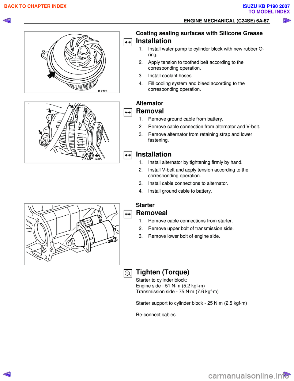
ENGINE MECHANICAL (C24SE) 6A-67
Coating sealing surfaces with Silicone Grease
Installation
1. Install water pump to cylinder block with new rubber O-ring.
2. Apply tension to toothed belt according to the corresponding operation.
3. Install coolant hoses.
4. Fill cooling system and bleed according to the corresponding operation.
Alternator
Removal
1. Remove ground cable from battery.
2. Remove cable connection from alternator and V-belt.
3. Remove alternator from retaining strap and lower fastening.
Installation
1. Install alternator by tightening firmly by hand.
2. Install V-belt and apply tension according to the corresponding operation.
3. Install cable connections to alternator.
4. Install ground cable to battery.
Starter
Removeal
1. Remove cable connections from starter.
2. Remove upper bolt of transmission side.
3. Remove lower bolt of engine side.
Tighten (Torque)
Starter to cylinder block:
Engine side - 51 N ⋅m (5.2 kgf ⋅m)
Transmission side - 75 N ⋅m (7.6 kgf ⋅m)
Starter support to cylinder block - 25 N ⋅m (2.5 kgf ⋅m)
Re-connect cables.
BACK TO CHAPTER INDEX
TO MODEL INDEX
ISUZU KB P190 2007
Page 2122 of 6020
6C-4 ENGINE FUEL (C24SE)
Fuel Metering
Engine Control Module (ECM) is in complete control of this fuel
delivery system during normal driving conditions.
The intake manifold function, like that of a diesel, is used onl
y
to let air into the engine. The fuel is injected by separate
injectors that are mounted over the intake manifold.
The Manifold Absolute Pressure (MAP) sensor measures the
changes in the intake manifold pressure which result from
engine load and speed changes, which the MAP senso
r
converts to a voltage output.
This sensor generates the voltage to change corresponding to
the flow of the air drawn into the engine.
The changing voltage is transformed into an electric signal and
provided to the ECM.
W ith receipt of the signals sent from the MAP sensor, Intake
Air Temperature sensor and others, the ECM determines an
appropriate fuel injection pulse width feeding such information
to the fuel injector valves to effect an appropriate air/fuel ratio.
The Multiport Fuel Injection system utilizes an injection system
where the injectors turn on at every crankshaft revolution. The
ECM controls the injector on time so that the correct amount o
f
fuel is metered depending on driving conditions.
Two interchangeable "O" rings are used on the injector that
must be replaced when the injectors are removed.
The fuel rail is attached to the top of the intake manifold and
supplies fuel to all the injectors.
Fuel is recirculated through the rail continually while the engine
is running. This removes air and vapors from the fuel as well
as keeping the fuel cool during hot weather operation.
The fuel pressure control valve that is mounted on the fuel rail
maintains a pressure differential across the injectors under all
operating conditions. It is accomplished by controlling the
amount of fuel that is recirculated back to the fuel tank based
on engine demand.
See Section "Driveability and Emission" for more information
and diagnosis.
BACK TO CHAPTER INDEX
TO MODEL INDEX
ISUZU KB P190 2007
Page 2238 of 6020
6E–68 ENGINE DRIVEABILITY AND EMISSIONS
On-Board Diagnostic (OBD)
On-Board Diagnostic Tests
A diagnostic test is a series of steps, the result of which
is a pass or fail reported to the diagnostic executive.
When a diagnostic test reports a pass result, the
diagnostic executive records the following data:
• The diagnostic test has been completed since the last ignition cycle.
• The diagnostic test has passed during the current ignition cycle.
• The fault identified by the diagnostic test is not currently active.
When a diagnostic test reports a fail result, the
diagnostic executive records the following data:
• The diagnostic test has been completed since the last ignition cycle.
• The fault identified by the diagnostic test is currently active.
• The fault has been active during this ignition cycle.
• The operating conditions at the time of the failure.
The Diagnostic Executive
The Diagnostic Executive is a unique segment of
software which is designed to coordinate and prioritize
the diagnostic procedures as well as define the protocol
for recording and displaying their results. The main
responsibilities of the Diagnostic Executive are listed as
follows:
• Commanding the check engine lamp on and off
• DTC logging and clearing
• Current status information on each diagnostic
Diagnostic Information
The diagnostic charts and functional checks are
designed to locate a faulty circuit or component through
a process of logical decisions. The charts are prepared
with the requirement that the vehicle functioned
correctly at the time of assembly and that there are not
multiple faults present.
There is a continuous self-diagnosis on certain control
functions. This diagnostic capability is complemented
by the diagnostic procedures contained in this manual.
The language of communicating the source of the
malfunction is a system of diagnostic trouble codes.
When a malfunction is detected by the control module, a
diagnostic trouble code is set and the check engine
lamp is illuminated.
Check Engine Lamp
The check engine lamp looks the same as the check
engine lamp you are already familiar with, the “Check
Engine” lamp.
Basically, the check engine lamp is turned on when the
ECM detects a DTC that will impact the vehicle
emissions.
• When the check engine lamp remains “ON” while the engine is running, or when a malfunction is suspected due to a driveability or emissions problem,
a Powertrain On-Board Diagnostic (OBD) System
Check must be performed. The procedures for these
checks are given in On-Board Diagnostic (OBD)
System Check. These checks will expose faults
which may not be detected if other diagnostics are
performed first.
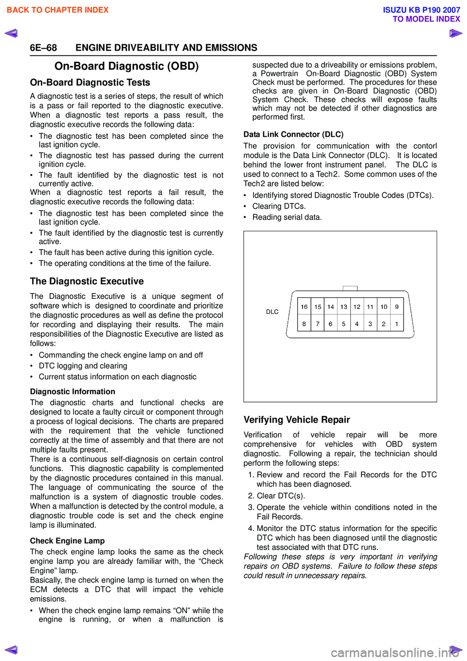
Data Link Connector (DLC)
The provision for communication with the contorl
module is the Data Link Connector (DLC). It is located
behind the lower front instrument panel. The DLC is
used to connect to a Tech 2. Some common uses of the
Tech 2 are listed below:
• Identifying stored Diagnostic Trouble Codes (DTCs).
• Clearing DTCs.
• Reading serial data.
Verifying Vehicle Repair
Verification of vehicle repair will be more
comprehensive for vehicles with OBD system
diagnostic. Following a repair, the technician should
perform the following steps:
1. Review and record the Fail Records for the DTC which has been diagnosed.
2. Clear DTC(s).
3. Operate the vehicle within conditions noted in the Fail Records.
4. Monitor the DTC status information for the specific DTC which has been diagnosed until the diagnostic
test associated with that DTC runs.
Following these steps is very important in verifying
repairs on OBD systems. Failure to follow these steps
could result in unnecessary repairs.
BACK TO CHAPTER INDEX
TO MODEL INDEX
ISUZU KB P190 2007
Page 2244 of 6020

6E–74 ENGINE DRIVEABILITY AND EMISSIONS
TYPICAL SCAN DATA & DEFINITIONS (O2 SENSOR DATA)
Use the Typical Values Table only after the On-Board Diagnostic System Check has been completed, no DTC(s) were
noted, and you have determined that the on-board diagnostics are functioning properly. Tech 2 values from a
properly-running engine may be used for comparison with the engine you are diagnosing.
Condition : Vehicle stopping, engine running, air conditioning off & after warm-up (Coolant temperature approximately
80 deg.)
Tech 2 ParameterUnitsIdle2000rpmDescription
1 Engine Speed rpm710 - 8751950 - 2050 The actual engine speed is measured by ECM from the
CKP sensor 58X signal.
2 Desired Idle Speed rpm825800 - 850 The desired engine idle speed that the ECMcommanding. The ECM compensates for various engine
loads.
3 Engine Coolant Temperature °C or °F80 - 9080 - 90 The ECT is measured by ECM from ECT sensor output
voltage. When the engine is normally warm upped, this
data displays approximately 80 °C or more.
4 Start Up ECT (Engine Coolant Temperature) °C or °FDepends on ECT
at start-upDepends on ECT at start-up Start-up ECT is measured by ECM from ECT sensor
output voltage when engine is started.
5Intake Air
Temperature °C or °FDepends on
ambient tempDepends on
ambient temp The IAT is measured by ECM from IAT sensor output
voltage. This data is changing by intake air temperature.
6 Start Up IAT (Intake Air Temperature) °C or °FDepends on IAT at
start-upDepends on IAT at start-up Start-up IAT is measured by ECM from IAT sensor output
voltage when engine is started.
7 Manifold Absolute Pressure kPa31 - 3625 - 30The MAP (kPa) is measured by ECM from MAP output
voltage. This data is changing by inlet manifold pressure.
8 Barometric Pressure kPaDepends on altitudeDepends on altitude The barometric pressure is measured by ECM from the
MAP sensor output voltage monitored during key up and
wide open throttle. This data is changing by altitude.
9 Throttle Position %02 - 4 Throttle position operating angle is measured by the ECM from throttle position output voltage. This should
display 0% at idle and 99 - 100% at full throttle.
10 Calculated Air Flow g/s3.5 -4.508.0 - 10.0 This displays intake air amount. The mass air flow is measured by ECM from the MAF sensor output voltage.
11 Air Fuel Ratio14.6:114.6:1 This displays the ECM commanded value. In closedloop, this should normally be displayed around 14.2:1 -
14.7:1.
12 Fuel System Status Open Loop/ Close LoopClose LoopClose Loop When the engine is first started the system is in “OpenLoop” operation. In “Open Loop”, the ECM ignores the
signal from the oxygen sensors. When various
conditions (ECT, time from start, engine speed & oxygen
sensor output) are met, the system enters “Closed Loop”
operation. In “Closed Loop”, the ECM calculates the air
fuel ratio based on the signal from the oxygen sensors.
13 Engine Load %2 - 55 - 10 This displays is calculated by the ECM form engine
speed and MAF sensor reading. Engine load should
increase with an increase in engine speed or air flow
amount.
14B1 O2 Sensor Ready
(Bank 1)Ye s / N oYe sYes This displays the status of the exhaust oxygen sensor. This display will indicate “Yes” when the ECM detects a
fluctuating oxygen sensor output voltage sufficient to
allow closed loop operation. This will not occur unless
the oxygen sensor is warmed up.
15B1S1 Status
(Bank 1 Sensor 1)Rich / LeanRich / LeanRich / Lean This displays dependent on the exhaust oxygen sensor output voltage. Should fluctuate constantly “Rich” and
“Lean” in closed loop.
16 Fuel Trim Learned Yes/NoYe sYes When conditions are appropriate for enabling long term fuel trim corrections, fuel trim learn will display “Yes”.
This indicates that the long term fuel trim is responding
to the short term fuel trim. If the fuel trim lean displays
“No”, then long term fuel trim will not respond to changes
in short term fuel trim.
BACK TO CHAPTER INDEX
TO MODEL INDEX
ISUZU KB P190 2007