2007 ISUZU KB P190 ESP
[x] Cancel search: ESPPage 1850 of 6020

ENGINE CONTROL SYSTEM (4JK1/4JJ1) 6E-233
51. Turn OFF the ignition.
2. Wait 1 minute for the fuel pressure to bleed down from the fuel rail.
3. Turn ON the ignition, with the engine OFF. DO NOT start the engine.
4. Observe the Fuel Rail Pressure (FRP) Sensor parameter with the scan tool.
Does the scan tool indicate within the specified
value? 0.9 to 1.0 volt
Go to Step 6 Go to Step 13
6 1. Turn OFF the ignition.
2. Place the transmission in Neutral and set the parking brake.
3. Start the engine and let idle for at least 3 minutes while observing the DTC Information
with a scan tool.
Does the DTC fail this ignition? —
Go to Step 8 Go to Step 7
7 1. Accelerate the engine between idle and
W.O.T. (accelerator pedal full travel) many
times.
2. Let idle for at least 3 minutes while observing the DTC Information with a scan tool.
Does the DTC fail this ignition? —
Go to Step 18 Go to Step 8
8 1. Start the engine.
2. Perform the Cylinder Balance Test with a scan tool.
3. Command each injector OFF and verify an engine speed change for each injector.
Is there an injector that does not change engine
speed when commanded OFF? —
Go to Step 16 Go to Step 9
9 1. Check the fuel system line connections
between the fuel tank and the fuel supply
pump for tightness and all fuel hoses for cuts,
cracks and for the use of proper clamps.
Notice: Air in the fuel system will cause fuel rail
pressure fluctuations especially at high engine
speed and load, which may set this DTC.
2. Repair or replace as necessary.
Did you find and correct the condition? —
Go to Step 19 Go to Step 10
Step
Action Value(s)Yes No
BACK TO CHAPTER INDEX
TO MODEL INDEX
ISUZU KB P190 2007
Page 1870 of 6020
ENGINE CONTROL SYSTEM (4JK1/4JJ1) 6E-253
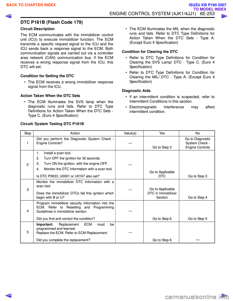
DTC P161B (Flash Code 179)
Circuit Description
The ECM communicates with the immobilizer control
unit (ICU) to execute immobilizer function. The ECM
transmits a specific request signal to the ICU and the
ICU sends back a response signal to the ECM. Both
communication signals are carried out via a controller
area network (CAN) communication bus. If the ECM
receives a wrong response signal from the ICU, this
DTC will set.
Condition for Setting the DTC • The ECM receives a wrong immobilizer response signal from the ICU.
Action Taken When the DTC Sets • The ECM illuminates the SVS lamp when the diagnostic runs and fails. Refer to DTC Type
Definitions for Action Taken When the DTC Sets -
Type C. (Euro 4 Specification) • The ECM illuminates the MIL when the diagnostic
runs and fails. Refer to DTC Type Definitions for
Action Taken When the DTC Sets - Type A.
(Except Euro 4 Specification)
Condition for Clearing the DTC • Refer to DTC Type Definitions for Condition for Clearing the SVS Lamp/ DTC - Type C. (Euro 4
Specification)
• Refer to DTC Type Definitions for Condition for Clearing the MIL/ DTC - Type A. (Except Euro 4
Specification)
Diagnostic Aids • If an intermittent condition is suspected, refer to Intermittent Conditions in this section.
• Electromagnetic interference may affect intermittent condition.
Circuit/ System Testing DTC P161B
Step Action Value(s)Yes No
1 Did you perform the Diagnostic System Check -
Engine Controls? —
Go to Step 2 Go to Diagnostic
System Check -
Engine Controls
2 1. Install a scan tool.
2. Turn OFF the ignition for 30 seconds.
3. Turn ON the ignition, with the engine OFF.
4. Monitor the DTC Information with a scan tool.
Is DTC P0633, U0001 or U0167 also set? —
Go to Applicable DTC Go to Step 3
3 Monitor the immobilizer DTC Information with a
scan tool.
Does the immobilizer DTCs fail this ignition which
begin with B or U? —
Go to Applicable
DTC in Immobilizer Section Go to Step 4
4 Program immobilizer security information into the
ECM. Refer to Resetting and Programming
Guidelines in immobilizer section.
Did you find and correct the condition? —
Go to Step 6 Go to Step 5
5 Important:
Replacement ECM must be
programmed and learned.
Replace the ECM. Refer to ECM Replacement.
Did you complete the replacement? —
Go to Step 6
—
BACK TO CHAPTER INDEX
TO MODEL INDEX
ISUZU KB P190 2007
Page 1918 of 6020
ENGINE CONTROL SYSTEM (4JK1/4JJ1) 6E-301
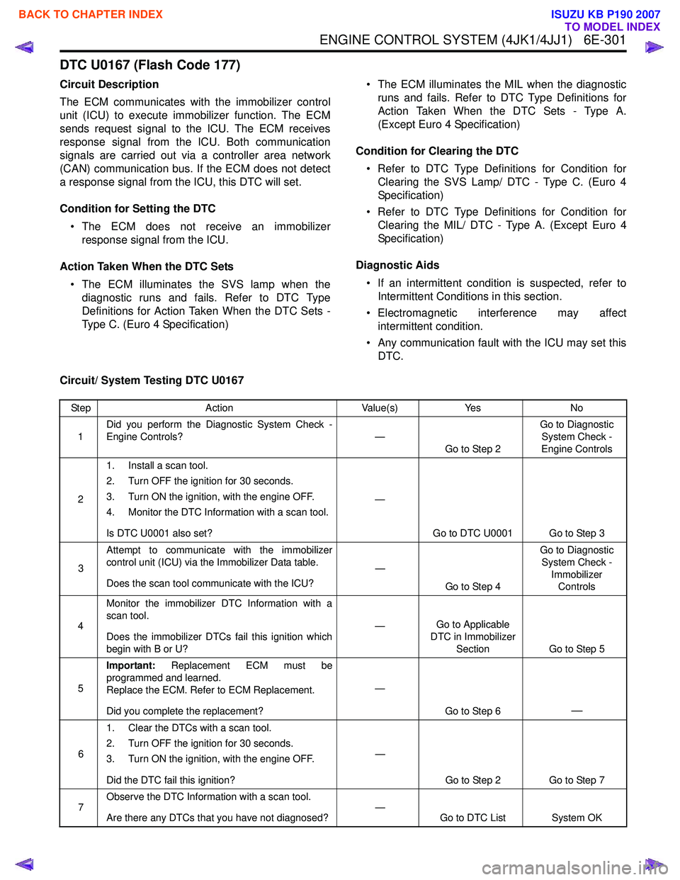
DTC U0167 (Flash Code 177)
Circuit Description
The ECM communicates with the immobilizer control
unit (ICU) to execute immobilizer function. The ECM
sends request signal to the ICU. The ECM receives
response signal from the ICU. Both communication
signals are carried out via a controller area network
(CAN) communication bus. If the ECM does not detect
a response signal from the ICU, this DTC will set.
Condition for Setting the DTC • The ECM does not receive an immobilizer response signal from the ICU.
Action Taken When the DTC Sets • The ECM illuminates the SVS lamp when the diagnostic runs and fails. Refer to DTC Type
Definitions for Action Taken When the DTC Sets -
Type C. (Euro 4 Specification) • The ECM illuminates the MIL when the diagnostic
runs and fails. Refer to DTC Type Definitions for
Action Taken When the DTC Sets - Type A.
(Except Euro 4 Specification)
Condition for Clearing the DTC • Refer to DTC Type Definitions for Condition for Clearing the SVS Lamp/ DTC - Type C. (Euro 4
Specification)
• Refer to DTC Type Definitions for Condition for Clearing the MIL/ DTC - Type A. (Except Euro 4
Specification)
Diagnostic Aids • If an intermittent condition is suspected, refer to Intermittent Conditions in this section.
• Electromagnetic interference may affect intermittent condition.
• Any communication fault with the ICU may set this DTC.
Circuit/ System Testing DTC U0167
Step Action Value(s)Yes No
1 Did you perform the Diagnostic System Check -
Engine Controls? —
Go to Step 2 Go to Diagnostic
System Check -
Engine Controls
2 1. Install a scan tool.
2. Turn OFF the ignition for 30 seconds.
3. Turn ON the ignition, with the engine OFF.
4. Monitor the DTC Information with a scan tool.
Is DTC U0001 also set? —
Go to DTC U0001 Go to Step 3
3 Attempt to communicate with the immobilizer
control unit (ICU) via the Immobilizer Data table.
Does the scan tool communicate with the ICU? —
Go to Step 4 Go to Diagnostic
System Check - Immobilizer Controls
4 Monitor the immobilizer DTC Information with a
scan tool.
Does the immobilizer DTCs fail this ignition which
begin with B or U? —
Go to Applicable
DTC in Immobilizer
Section Go to Step 5
5 Important:
Replacement ECM must be
programmed and learned.
Replace the ECM. Refer to ECM Replacement.
Did you complete the replacement? —
Go to Step 6
—
61. Clear the DTCs with a scan tool.
2. Turn OFF the ignition for 30 seconds.
3. Turn ON the ignition, with the engine OFF.
Did the DTC fail this ignition? —
Go to Step 2 Go to Step 7
7 Observe the DTC Information with a scan tool.
Are there any DTCs that you have not diagnosed? —
Go to DTC List System OK
BACK TO CHAPTER INDEX
TO MODEL INDEX
ISUZU KB P190 2007
Page 1955 of 6020
6E-338 ENGINE CONTROL SYSTEM (4JK1/4JJ1)
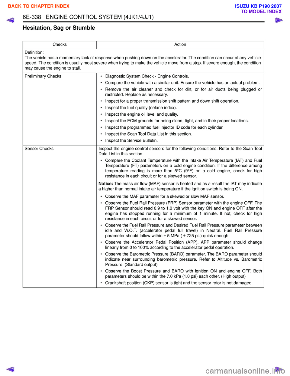
Hesitation, Sag or Stumble
ChecksAction
Definition:
The vehicle has a momentary lack of response when pushing down on the accelerator. The condition can occur at any vehicle
speed. The condition is usually most severe when trying to make the vehicle move from a stop. If severe enough, the condition
may cause the engine to stall.
Preliminary Checks • Diagnostic System Check - Engine Controls.
• Compare the vehicle with a similar unit. Ensure the vehicle has an actual problem.
• Remove the air cleaner and check for dirt, or for air ducts being plugged or restricted. Replace as necessary.
• Inspect for a proper transmission shift pattern and down shift operation.
• Inspect the fuel quality (cetane index).
• Inspect the engine oil level and quality.
• Inspect the ECM grounds for being clean, tight, and in their proper locations.
• Inspect the programmed fuel injector ID code for each cylinder.
• Inspect the Scan Tool Data List in this section.
• Inspect the Service Bulletin.
Sensor Checks Inspect the engine control sensors for the following conditions. Refer to the Scan Tool
Data List in this section.
• Compare the Coolant Temperature with the Intake Air Temperature (IAT) and Fuel Temperature (FT) parameters on a cold engine condition. If the difference among
temperature reading is more than 5 °C (9 °F) on a cold engine, check for high
resistance in each circuit or for a skewed sensor.
Notice: The mass air flow (MAF) sensor is heated and as a result the IAT may indicate
a higher than normal intake air temperature if the ignition switch is being ON.
• Observe the MAF parameter for a skewed or slow MAF sensor.
• Observe the Fuel Rail Pressure (FRP) Sensor parameter with the engine OFF. The FRP Sensor should read 0.9 to 1.0 volt with the key ON and engine OFF after the
engine has stopped running for a minimum of 1 minute. If not, check for high
resistance in each circuit or for a skewed sensor.
• Observe the Fuel Rail Pressure and Desired Fuel Rail Pressure parameter between idle and W.O.T. (accelerator pedal full travel) in Neutral. Fuel Rail Pressure
parameter should follow within ± 5 MPa ( ± 725 psi) quick enough.
• Observe the Accelerator Pedal Position (APP). APP parameter should change linearly from 0 to 100% according to the accelerator pedal operation.
• Observe the Barometric Pressure (BARO) parameter. The BARO parameter should indicate near surrounding barometric pressure. Refer to Altitude vs. Barometric
Pressure. (Standard output)
• Observe the Boost Pressure and BARO with ignition ON and engine OFF. Both parameters should be within the 7.0 kPa (1.0 psi) each other. (High output)
• Crankshaft position (CKP) sensor is tight and the sensor rotor is not damaged.
BACK TO CHAPTER INDEX
TO MODEL INDEX
ISUZU KB P190 2007
Page 1977 of 6020
6E-360 ENGINE CONTROL SYSTEM (4JK1/4JJ1)
1. High Pressure Control• Enables high pressure injection from low engine speed range.
• Optimizes control to minimize particulate matter and NOx emissions.
2. Injection Timing Control
• Enables finely tuned optimized control in accordance with running conditions.
3. Injection Rate Control
• Pilot injection control that performs a small amount of injection before main injection.
The fuel rail system consists primarily of a fuel supply
pump, fuel rail, injectors, and ECM.
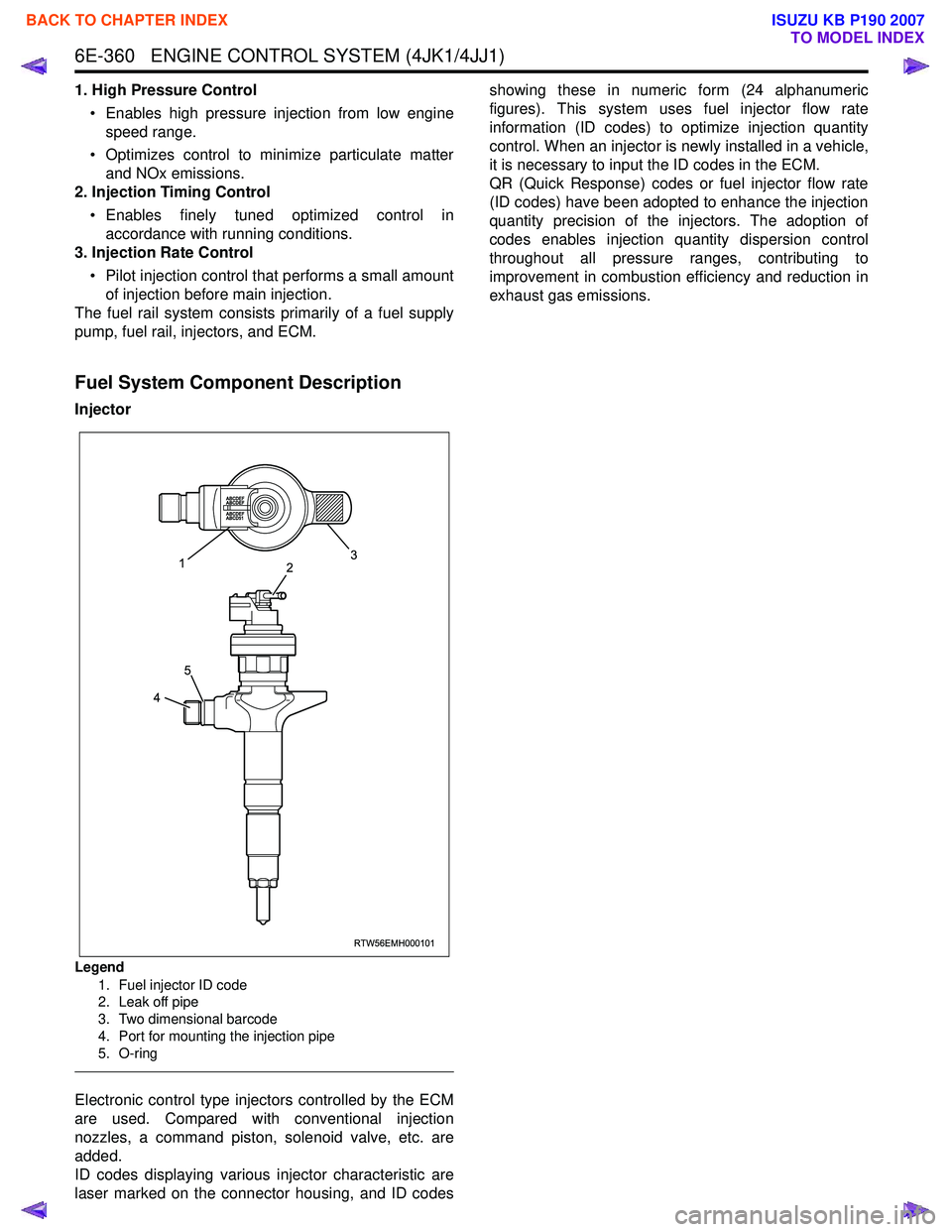
Fuel System Component Description
Injector
Legend
1. Fuel injector ID code
2. Leak off pipe
3. Two dimensional barcode
4. Port for mounting the injection pipe
5. O-ring
Electronic control type injectors controlled by the ECM
are used. Compared with conventional injection
nozzles, a command piston, solenoid valve, etc. are
added.
ID codes displaying various injector characteristic are
laser marked on the connector housing, and ID codes showing these in numeric form (24 alphanumeric
figures). This system uses fuel injector flow rate
information (ID codes) to optimize injection quantity
control. When an injector is newly installed in a vehicle,
it is necessary to input the ID codes in the ECM.
QR (Quick Response) codes or fuel injector flow rate
(ID codes) have been adopted to enhance the injection
quantity precision of the injectors. The adoption of
codes enables injection quantity dispersion control
throughout all pressure ranges, contributing to
improvement in combustion efficiency and reduction in
exhaust gas emissions.
RTW56EMH000101
23
1
4
5
BACK TO CHAPTER INDEX
TO MODEL INDEX
ISUZU KB P190 2007
Page 1980 of 6020
ENGINE CONTROL SYSTEM (4JK1/4JJ1) 6E-363
Along with the employment of a common rail type
electronic control fuel injection system, the fuel rail is
provided to store high pressure fuel between supply
pump and injectors. A pressure sensor and a pressure
limiter are installed on the fuel rail. The pressure sensor
detects the fuel pressure inside the fuel rail and sends
its signal to the ECM. Based on this signal, the ECM
controls the fuel pressure inside the fuel rail via the fuel
rail pressure (FRP) regulator of the supply pump. The
pressure limiter opens the valve mechanically to relieve
the pressure when the fuel pressure inside the fuel rail
is excessive.
Fuel Rail Pressure Sensor
The FRP sensor is installed to the fuel rail and it
detects the fuel pressure in the fuel rail, converts the
pressure into a voltage signal, and sends the signal to
the ECM. The ECM monitors the FRP sensor signal
voltage. Higher fuel rail pressure provides higher signal
voltage while lower pressure provides lower signal
voltage. The ECM calculates actual fuel rail pressure
(fuel pressure) from the voltage signal and uses the
result in fuel injection control and other control tasks.
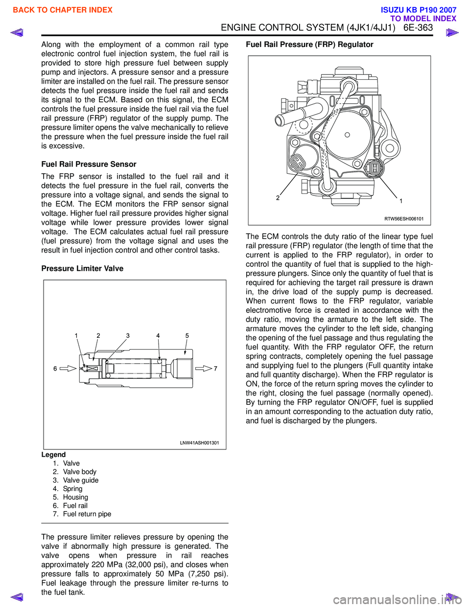
Pressure Limiter Valve
Legend 1. Valve
2. Valve body
3. Valve guide
4. Spring
5. Housing
6. Fuel rail
7. Fuel return pipe
The pressure limiter relieves pressure by opening the
valve if abnormally high pressure is generated. The
valve opens when pressure in rail reaches
approximately 220 MPa (32,000 psi), and closes when
pressure falls to approximately 50 MPa (7,250 psi).
Fuel leakage through the pressure limiter re-turns to
the fuel tank. Fuel Rail Pressure (FRP) Regulator
The ECM controls the duty ratio of the linear type fuel
rail pressure (FRP) regulator (the length of time that the
current is applied to the FRP regulator), in order to
control the quantity of fuel that is supplied to the high-
pressure plungers. Since only the quantity of fuel that is
required for achieving the target rail pressure is drawn
in, the drive load of the supply pump is decreased.
When current flows to the FRP regulator, variable
electromotive force is created in accordance with the
duty ratio, moving the armature to the left side. The
armature moves the cylinder to the left side, changing
the opening of the fuel passage and thus regulating the
fuel quantity. With the FRP regulator OFF, the return
spring contracts, completely opening the fuel passage
and supplying fuel to the plungers (Full quantity intake
and full quantity discharge). When the FRP regulator is
ON, the force of the return spring moves the cylinder to
the right, closing the fuel passage (normally opened).
By turning the FRP regulator ON/OFF, fuel is supplied
in an amount corresponding to the actuation duty ratio,
and fuel is discharged by the plungers.
LNW41ASH001301
12 3 4 5
7
6
RTW56ESH006101
12
BACK TO CHAPTER INDEX
TO MODEL INDEX
ISUZU KB P190 2007
Page 1981 of 6020
6E-364 ENGINE CONTROL SYSTEM (4JK1/4JJ1)
Fuel Injection System Description
Fuel Injection Quantity Control
This control determines the fuel injection quantity by
adding coolant temperature, fuel temperature, intake
air temperature, barometric pressure, mass air flow and
some switch inputs information corrections to the basic
injection quantity is calculated by the ECM based on
the engine operating conditions (engine speed,
accelerator pedal pressing amount and boost pressure
sensor). More fuel rate indicates if the engine load is
increased as the accelerator pedal is stepped on at
constant engine speed.
Combined with high pressure injection of atomized fuel,
this control improves exhaust gas and ensures proper
fuel consumption. Compared with conventional
mechanical governors, an electronic control system
provides higher degree of freedom of fuel injection
quantity control, thereby presenting high accelerator
response (acceleration feeling and pressing feeling).
Starting Injection Quantity Control
At the engine starting (after the key switch is turned to
the START position to start the engine, up to return of
key switch to the ON position), optimum fuel injection
quantity is controlled based on the information on the
engine speed and coolant temperature. At low
temperature, the fuel injection quantity increases.
When the engine started completely, this boosted
quantity mode at the starting is cancelled and normal
running mode is restored.
Idle Speed Control
A control is made so as to achieve stable idling speed
at all time regardless of engine secular changes or
engine condition variations. The ECM sets target idling
speed and controls the fuel injection quantity according
to the engine conditions (actual engine speed, coolant
temperature and engine load) to follow actual engine
speed to the target idling speed so as to ensure stable
idling speed.
Idle Vibration Control
A control is made so as to reduce the engine vibration
caused by torque variations between cylinders due to
variations in fuel injection quantity of each cylinder or
injector performance. The ECM corrects the injection
quantity between cylinders based on the revolution
signals from the crankshaft position (CKP) sensor.
Normal range of correction quantity between cylinders
is within ±5 mm
3.
BACK TO CHAPTER INDEX
TO MODEL INDEX
ISUZU KB P190 2007
Page 2034 of 6020

6A-20 ENGINE MECHANICAL (C24SE)
6. Install power steering pump and V-belt.
Adjust
Adjust power steering pump V-belt tension according to the
corresponding operation.
Installation
7. Install radiator according to the corresponding operation.
8. Install air inlet hose.
9. Install all electrical cable connections, hoses and lines to engine.
10. Install accelerator cable from inlet pipe.
11. Install bonnet.
Inspection
1. Check engine oil level.
2. Fill up cooling system and bleed according to the corresponding operation.
BACK TO CHAPTER INDEX
TO MODEL INDEX
ISUZU KB P190 2007