2007 ISUZU KB P190 ESP
[x] Cancel search: ESPPage 1556 of 6020
FUEL SYSTEM (4JK1/4JJ1) 6C-15
The fuel system consists of many tiny holes and spaces
that allow the movement of fuel from one place to
another. These holes and spaces are milled to
extremely high precision. This is especially true of the
fuel injector.
The fuel injector is very sensitive to foreign material.
Foreign material will result in fuel system breakdown.
Exercise great care not to allow the entry of foreign
material into the fuel system or fuel injector during the
removal and installation procedure.
Note: To avoid electric shock;
Set the switch to the 'OFF' position and disconnect the
negative battery cable before checking or repairing the
fuel injector, wiring or/and connectors.
Removal
1. Remove the cylinder head cover.
Refer to the removal procedure for the cylinde
r
head cover in this manual.
Remove the attachment bolt of the engine oil gauge
guide tube.
2. Loosen the fuel injector clamp fixing bolts and
remove the fuel injector.
If the fuel injector is difficult to remove, use the remover. Use a screwdriver to force the fuel
injector clamp off the fuel injector.
Note: Do not remove the fuel injector sleeve.
Note: Cover the areas exposed during parts removal to
prevent the entry of foreign material into the fuel
system.
3. Mark each fuel injector with the number of the cylinder from which it was removed. Store the fuel
injector in a safe place. Position the fuel injector so
that the nozzle is protected.
Note: Do not tamper with the electromagnetic portion of
the fuel injector. Reduced electromagnetic function will
result in injector failure.
Note: After replacement of the fuel injector, perform the
following procedure.
• All fuel injectors are replaced:
Remove the fuel injector ID code label on the cylinder head cover.
• Any fuel injector(s) is replaced:
Black out the replaced cylinder of the fuel injecto
r
ID code on the fuel injector ID code label with a
marking pen or equivalent.
Installation
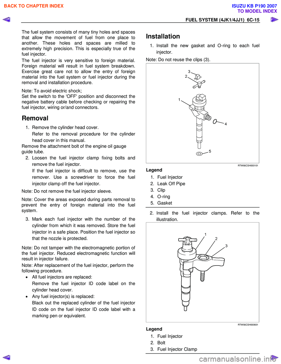
1. Install the new gasket and O-ring to each fuel
injector.
Note: Do not reuse the clips (3).
RTW 66CSH000101
Legend
1. Fuel Injector
2. Leak Off Pipe
3. Clip
4. O-ring
5. Gasket
2. Install the fuel injector clamps. Refer to the
illustration.
RTW 56CSH000601
Legend
1. Fuel Injector
2. Bolt
3. Fuel Injector Clamp
BACK TO CHAPTER INDEX
TO MODEL INDEX
ISUZU KB P190 2007
Page 1568 of 6020
FUEL SYSTEM (4JK1/4JJ1) 6C-27
Fuel Supply Pump
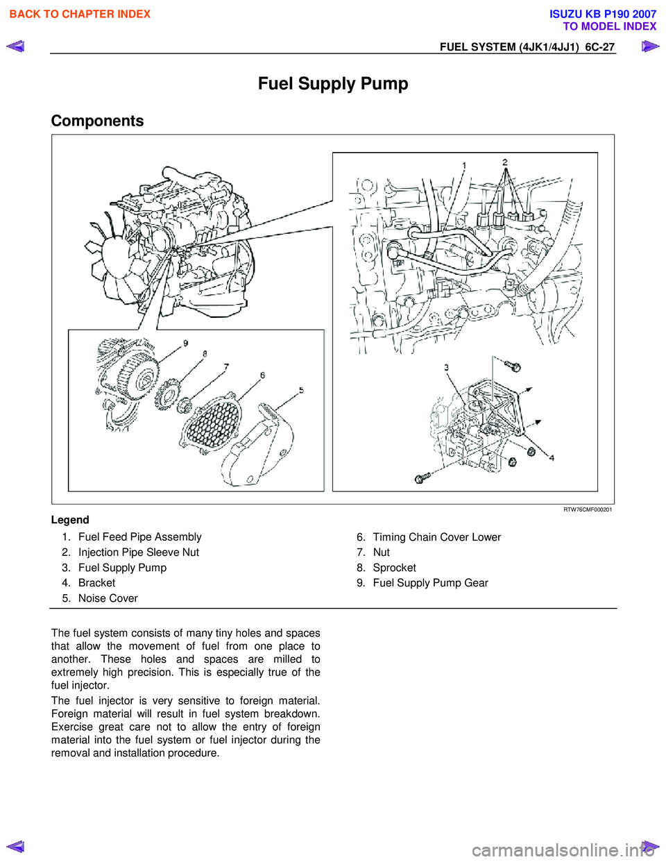
Components
RTW 76CMF000201
Legend
1. Fuel Feed Pipe Assembly
2. Injection Pipe Sleeve Nut
3. Fuel Supply Pump
4. Bracket 5. Noise Cover
6. Timing Chain Cover Lower
7. Nut
8. Sprocket
9. Fuel Supply Pump Gear
The fuel system consists of many tiny holes and spaces
that allow the movement of fuel from one place to
another. These holes and spaces are milled to
extremely high precision. This is especially true of the
fuel injector.
The fuel injector is very sensitive to foreign material.
Foreign material will result in fuel system breakdown.
Exercise great care not to allow the entry of foreign
material into the fuel system or fuel injector during the
removal and installation procedure.
BACK TO CHAPTER INDEX
TO MODEL INDEX
ISUZU KB P190 2007
Page 1624 of 6020
ENGINE CONTROL SYSTEM (4JK1/4JJ1) 6E-7
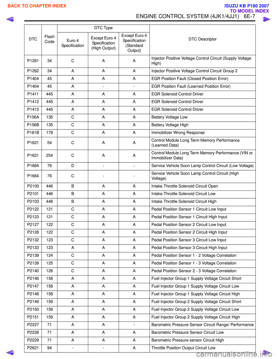
P1261 34 CAAInjector Positive Voltage Control Circuit (Supply Voltage
High)
P1262 34 A AA Injector Positive Voltage Control Circuit Group 2
P1404 45 A AA EGR Position Fault (Closed Position Error)
P1404 45 A -- EGR Position Fault (Learned Position Error)
P1411 445 A AA EGR Solenoid Control Driver
P1412 445 A AA EGR Solenoid Control Driver
P1413 445 A AA EGR Solenoid Control Driver
P156A 135 C AA Battery Voltage Low
P156B 135 C AA Battery Voltage High
P161B 179 C AA Immobilizer Wrong Response
P1621 54 C AAControl Module Long Term Memory Performance
(Learned Data)
P1621 254 C AAControl Module Long Term Memory Performance (VIN or
Immobilizer Data)
P1664 76 D -- Service Vehicle Soon Lamp Control Circuit (Low Voltage)
P1664 76 C --Service Vehicle Soon Lamp Control Circuit (High
Voltage)
P2100 446 B AA Intake Throttle Solenoid Circuit Open
P2101 446 B AA Intake Throttle Solenoid Circuit Low
P2103 446 B AA Intake Throttle Solenoid Circuit High
P2122 121 C AA Pedal Position Sensor 1 Circuit Low Input
P2123 121 C AA Pedal Position Sensor 1 Circuit High Input
P2127 122 C AA Pedal Position Sensor 2 Circuit Low Input
P2128 122 C AA Pedal Position Sensor 2 Circuit High Input
P2132 123 C AA Pedal Position Sensor 3 Circuit Low Input
P2133 123 A AA Pedal Position Sensor 3 Circuit High Input
P2138 124 C AA Pedal Position Sensor 1 - 2 Voltage Correlation
P2139 125 C AA Pedal Position Sensor 1 - 3 Voltage Correlation
P2140 126 C AA Pedal Position Sensor 2 - 3 Voltage Correlation
P2146 158 A AA Fuel Injector Group 1 Supply Voltage Circuit Short
P2147 158 A AA Fuel Injector Group 1 Supply Voltage Circuit Low
P2148 158 A AA Fuel Injector Group 1 Supply Voltage Circuit High
P2149 159 A AA Fuel Injector Group 2 Supply Voltage Circuit Short
P2150 159 A AA Fuel Injector Group 2 Supply Voltage Circuit Low
P2151 159 A AA Fuel Injector Group 2 Supply Voltage Circuit High
P2227 71 A A- Barometric Pressure Sensor Circuit Range/ Performance
P2228 71 A AA Barometric Pressure Sensor Circuit Low
P2229 71 A AA Barometric Pressure sensor Circuit High
P2621 94 - -A Throttle Position Output Circuit Low
DTC
Flash
Code DTC Type
DTC Descriptor
Euro 4
Specification Except Euro 4
Specification
(High Output) Except Euro 4
Specification (Standard Output)
BACK TO CHAPTER INDEX
TO MODEL INDEX
ISUZU KB P190 2007
Page 1671 of 6020
6E-54 ENGINE CONTROL SYSTEM (4JK1/4JJ1)
Cruise Cancel Switch
This parameter displays the input state of the cruise
cancel switch to the ECM. When the Cruise Cancel
switch is applied, the scan tool displays Off.
Cruise Resume Switch
This parameter displays the input state of the cruise
resume/accel. switch to the ECM. When the Cruise
Resume/Accel. switch is applied, the scan tool displays
On.
Cruise Set Switch
This parameter displays the input state of the cruise
set/coast switch to the ECM. When the Cruise Set/
Coast switch is pushed, the scan tool displays On.
MIL Command (Malfunction Indicator Lamp)
This parameter displays the commanded state of the
malfunction indicator lamp (MIL) control circuit. The
MIL should be On when the scan tool indicates
command On. The MIL should be Off when the scan
tool indicates command Off.
SVS Lamp Command (Service Vehicle Soon)
This parameter displays the commanded state of the
service vehicle soon (SVS) lamp control circuit. The
SVS lamp should be On when the scan tool indicates
command On. The SVS lamp should be Off when the
scan tool indicates command Off.
Limp Home Mode
This parameter indicates the state of the limp-home
mode. None indicates limp-home mode is not applied.
1, 2, 3 and 4 indicates fuel injection quantity reduction
is applied. 2 or higher number inhibits pilot injection. If 4
is indicated, engine running will be stopped when the
vehicle speed is less than 5 km/h (3 MPH) for 5
seconds.
Distance While MIL is Activated
This parameter displays the mileage since the
malfunction indicator lamp (MIL) is turned ON.
Engine Runtime With MIL Active
This parameter displays the engine run time elapsed
since the malfunction indicator lamp (MIL) is turned
ON. The scan tool will display the time in minutes.
Total Engine Overspeed Event
This parameter indicates counter of engine overspeed
event. Counter will be zero if any DTC is cleared.
Total Engine Coolant Overtemperature Event
This parameter indicates counter of engine overheat
event. The counter is active if engine coolant is over
11 0 °C (230 °F). Counter will be zero if any DTC is
cleared. Total Fuel Temperature Overtemperature Event
This parameter indicates counter of fuel temperature
excessively high condition. The counter is active if fuel
temperature is over 95 °C (203 °F). Counter will be zero
if any DTC is cleared.
Total Intake Air Temperature Overtemperature
Event
This parameter indicates counter of intake air
temperature excessively high condition. The counter is
active if intake air temperature is over 55 °C (131 °F).
Counter will be zero if any DTC is cleared.
Immobilizer Function Programmed
This parameter displays the state of the immobilizer
function programming in the ECM. The scan tool will
display Yes or No. Yes indicates the immobilizer
security information is correctly programmed in the
ECM. No indicates the ECM is not programmed or
ECM is reset.
Wrong Immobilizer Signal
This parameter displays the input state of the received
response signal to the ECM. When the ECM received
wrong response signal from the immobilizer control unit
(ICU), the scan tool displays Yes.
Immobilizer Signal
This parameter displays the input state of the response
signal to the ECM. When the ECM received any
response signal from the immobilizer control unit (ICU),
the scan tool displays Yes.
Security Wait Time
This parameter displays the security wait time length in
the ECM. Inactive indicates not in security wait time.
Time indicates under security wait time. This wait time
stage will prevent any further attempts to enter the
security code until the wait time has elapsed. The wait
time will increase each time an incorrect security code
is entered. Note that this parameter is not count
downed. It keeps displaying the same time until that
wait time has elapsed. The ignition switch must be kept
at ON position during the wait time period.
BACK TO CHAPTER INDEX
TO MODEL INDEX
ISUZU KB P190 2007
Page 1692 of 6020
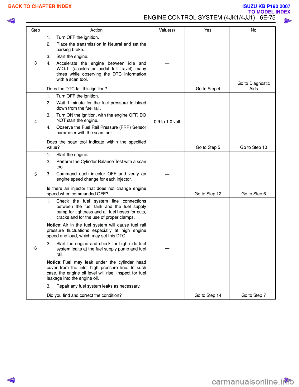
ENGINE CONTROL SYSTEM (4JK1/4JJ1) 6E-75
31. Turn OFF the ignition.
2. Place the transmission in Neutral and set the parking brake.
3. Start the engine.
4. Accelerate the engine between idle and W.O.T. (accelerator pedal full travel) many
times while observing the DTC Information
with a scan tool.
Does the DTC fail this ignition? —
Go to Step 4 Go to Diagnostic
Aids
4 1. Turn OFF the ignition.
2. Wait 1 minute for the fuel pressure to bleed down from the fuel rail.
3. Turn ON the ignition, with the engine OFF. DO NOT start the engine.
4. Observe the Fuel Rail Pressure (FRP) Sensor parameter with the scan tool.
Does the scan tool indicate within the specified
value? 0.9 to 1.0 volt
Go to Step 5 Go to Step 10
5 1. Start the engine.
2. Perform the Cylinder Balance Test with a scan tool.
3. Command each injector OFF and verify an engine speed change for each injector.
Is there an injector that does not change engine
speed when commanded OFF? —
Go to Step 12 Go to Step 6
6 1. Check the fuel system line connections
between the fuel tank and the fuel supply
pump for tightness and all fuel hoses for cuts,
cracks and for the use of proper clamps.
Notice: Air in the fuel system will cause fuel rail
pressure fluctuations especially at high engine
speed and load, which may set this DTC.
2. Start the engine and check for high side fuel system leaks at the fuel supply pump and fuel
rail.
Notice: Fuel may leak under the cylinder head
cover from the inlet high pressure line. In such
case, the engine oil level will rise. Inspect for fuel
leakage into the engine oil.
3. Repair any fuel system leaks as necessary.
Did you find and correct the condition? —
Go to Step 14 Go to Step 7
Step
Action Value(s)Yes No
BACK TO CHAPTER INDEX
TO MODEL INDEX
ISUZU KB P190 2007
Page 1697 of 6020
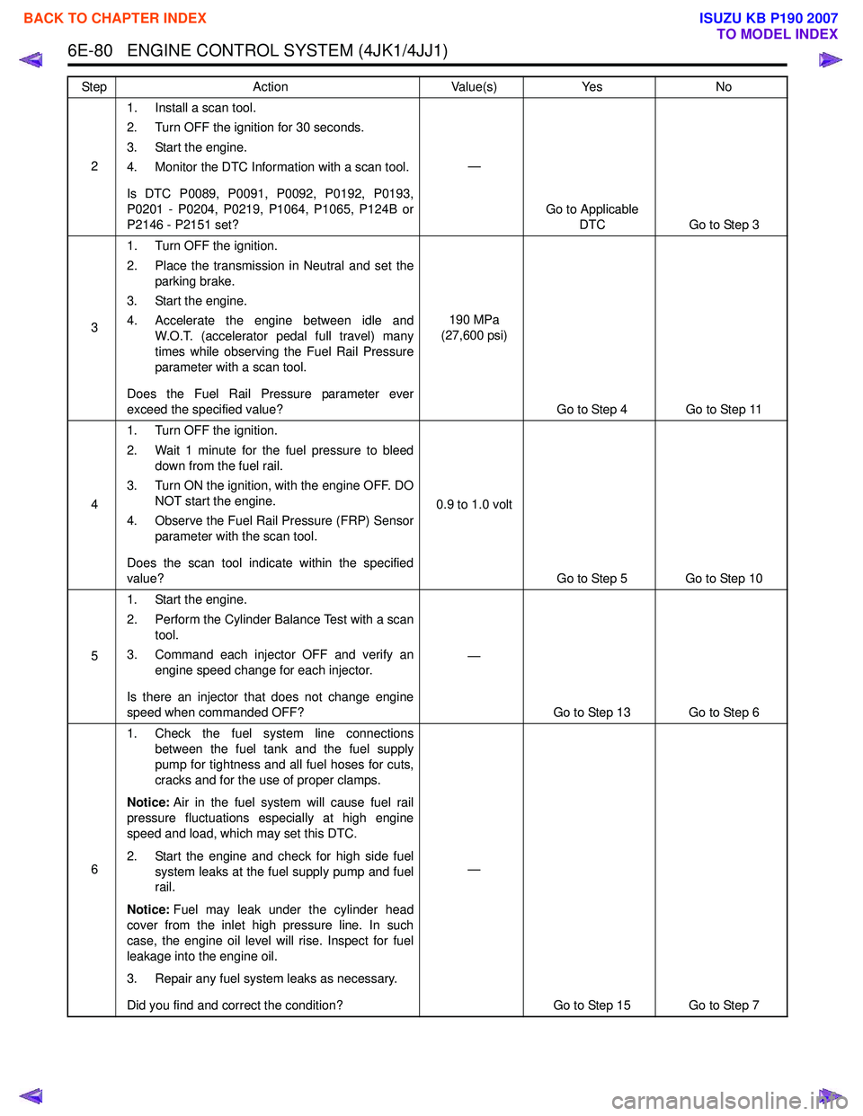
6E-80 ENGINE CONTROL SYSTEM (4JK1/4JJ1)
21. Install a scan tool.
2. Turn OFF the ignition for 30 seconds.
3. Start the engine.
4. Monitor the DTC Information with a scan tool.
Is DTC P0089, P0091, P0092, P0192, P0193,
P0201 - P0204, P0219, P1064, P1065, P124B or
P2146 - P2151 set? —
Go to Applicable DTC Go to Step 3
3 1. Turn OFF the ignition.
2. Place the transmission in Neutral and set the parking brake.
3. Start the engine.
4. Accelerate the engine between idle and W.O.T. (accelerator pedal full travel) many
times while observing the Fuel Rail Pressure
parameter with a scan tool.
Does the Fuel Rail Pressure parameter ever
exceed the specified value? 190 MPa
(27,600 psi)
Go to Step 4 Go to Step 11
4 1. Turn OFF the ignition.
2. Wait 1 minute for the fuel pressure to bleed down from the fuel rail.
3. Turn ON the ignition, with the engine OFF. DO NOT start the engine.
4. Observe the Fuel Rail Pressure (FRP) Sensor parameter with the scan tool.
Does the scan tool indicate within the specified
value? 0.9 to 1.0 volt
Go to Step 5 Go to Step 10
5 1. Start the engine.
2. Perform the Cylinder Balance Test with a scan tool.
3. Command each injector OFF and verify an engine speed change for each injector.
Is there an injector that does not change engine
speed when commanded OFF? —
Go to Step 13 Go to Step 6
6 1. Check the fuel system line connections
between the fuel tank and the fuel supply
pump for tightness and all fuel hoses for cuts,
cracks and for the use of proper clamps.
Notice: Air in the fuel system will cause fuel rail
pressure fluctuations especially at high engine
speed and load, which may set this DTC.
2. Start the engine and check for high side fuel system leaks at the fuel supply pump and fuel
rail.
Notice: Fuel may leak under the cylinder head
cover from the inlet high pressure line. In such
case, the engine oil level will rise. Inspect for fuel
leakage into the engine oil.
3. Repair any fuel system leaks as necessary.
Did you find and correct the condition? —
Go to Step 15 Go to Step 7
Step
Action Value(s)Yes No
BACK TO CHAPTER INDEX
TO MODEL INDEX
ISUZU KB P190 2007
Page 1709 of 6020
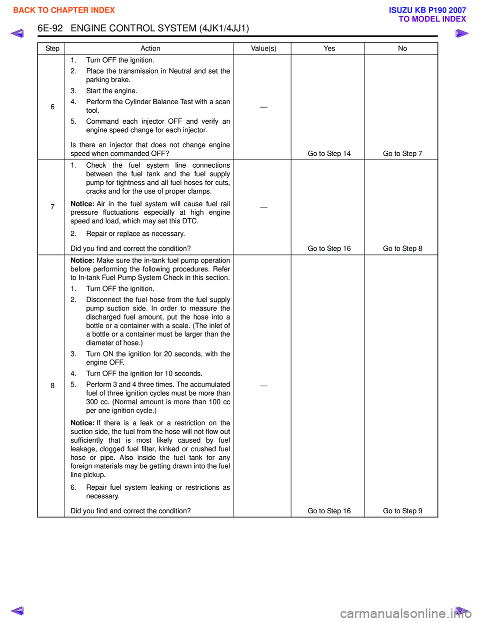
6E-92 ENGINE CONTROL SYSTEM (4JK1/4JJ1)
61. Turn OFF the ignition.
2. Place the transmission in Neutral and set the parking brake.
3. Start the engine.
4. Perform the Cylinder Balance Test with a scan tool.
5. Command each injector OFF and verify an engine speed change for each injector.
Is there an injector that does not change engine
speed when commanded OFF? —
Go to Step 14 Go to Step 7
7 1. Check the fuel system line connections
between the fuel tank and the fuel supply
pump for tightness and all fuel hoses for cuts,
cracks and for the use of proper clamps.
Notice: Air in the fuel system will cause fuel rail
pressure fluctuations especially at high engine
speed and load, which may set this DTC.
2. Repair or replace as necessary.
Did you find and correct the condition? —
Go to Step 16 Go to Step 8
8 Notice:
Make sure the in-tank fuel pump operation
before performing the following procedures. Refer
to In-tank Fuel Pump System Check in this section.
1. Turn OFF the ignition.
2. Disconnect the fuel hose from the fuel supply pump suction side. In order to measure the
discharged fuel amount, put the hose into a
bottle or a container with a scale. (The inlet of
a bottle or a container must be larger than the
diameter of hose.)
3. Turn ON the ignition for 20 seconds, with the engine OFF.
4. Turn OFF the ignition for 10 seconds.
5. Perform 3 and 4 three times. The accumulated fuel of three ignition cycles must be more than
300 cc. (Normal amount is more than 100 cc
per one ignition cycle.)
Notice: If there is a leak or a restriction on the
suction side, the fuel from the hose will not flow out
sufficiently that is most likely caused by fuel
leakage, clogged fuel filter, kinked or crushed fuel
hose or pipe. Also inside the fuel tank for any
foreign materials may be getting drawn into the fuel
line pickup.
6. Repair fuel system leaking or restrictions as necessary.
Did you find and correct the condition? —
Go to Step 16 Go to Step 9
Step
Action Value(s)Yes No
BACK TO CHAPTER INDEX
TO MODEL INDEX
ISUZU KB P190 2007
Page 1844 of 6020
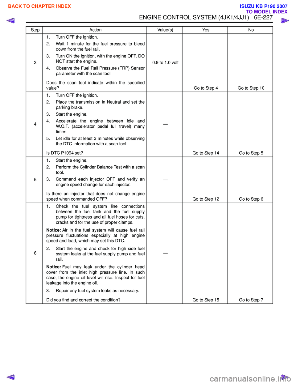
ENGINE CONTROL SYSTEM (4JK1/4JJ1) 6E-227
31. Turn OFF the ignition.
2. Wait 1 minute for the fuel pressure to bleed down from the fuel rail.
3. Turn ON the ignition, with the engine OFF. DO NOT start the engine.
4. Observe the Fuel Rail Pressure (FRP) Sensor parameter with the scan tool.
Does the scan tool indicate within the specified
value? 0.9 to 1.0 volt
Go to Step 4 Go to Step 10
4 1. Turn OFF the ignition.
2. Place the transmission in Neutral and set the parking brake.
3. Start the engine.
4. Accelerate the engine between idle and W.O.T. (accelerator pedal full travel) many
times.
5. Let idle for at least 3 minutes while observing the DTC Information with a scan tool.
Is DTC P1094 set? —
Go to Step 14 Go to Step 5
5 1. Start the engine.
2. Perform the Cylinder Balance Test with a scan tool.
3. Command each injector OFF and verify an engine speed change for each injector.
Is there an injector that does not change engine
speed when commanded OFF? —
Go to Step 12 Go to Step 6
6 1. Check the fuel system line connections
between the fuel tank and the fuel supply
pump for tightness and all fuel hoses for cuts,
cracks and for the use of proper clamps.
Notice: Air in the fuel system will cause fuel rail
pressure fluctuations especially at high engine
speed and load, which may set this DTC.
2. Start the engine and check for high side fuel system leaks at the fuel supply pump and fuel
rail.
Notice: Fuel may leak under the cylinder head
cover from the inlet high pressure line. In such
case, the engine oil level will rise. Inspect for fuel
leakage into the engine oil.
3. Repair any fuel system leaks as necessary.
Did you find and correct the condition? —
Go to Step 15 Go to Step 7
Step
Action Value(s)Yes No
BACK TO CHAPTER INDEX
TO MODEL INDEX
ISUZU KB P190 2007