Page 3993 of 6020
![ISUZU KB P190 2007 Workshop Repair Manual TRANSMISSION CONTROL SYSTEM (AW30–40LE) 7A2-27
After recording the snapshot in Tech2, transfer the data
from Tech2 to PC by the below procedures.
1. Start TIS2000.
2. Select [Snapshot Upload] ISUZU KB P190 2007 Workshop Repair Manual TRANSMISSION CONTROL SYSTEM (AW30–40LE) 7A2-27
After recording the snapshot in Tech2, transfer the data
from Tech2 to PC by the below procedures.
1. Start TIS2000.
2. Select [Snapshot Upload]](/manual-img/61/57177/w960_57177-3992.png)
TRANSMISSION CONTROL SYSTEM (AW30–40LE) 7A2-27
After recording the snapshot in Tech2, transfer the data
from Tech2 to PC by the below procedures.
1. Start TIS2000.
2. Select [Snapshot Upload] on the TIS2000 start
screen.
3. Select [Upload from trouble diagnosis tool (transfe
r
from diagnosis tester)] or click the corresponding
icon of the tool bar.
4. Select Tech2, and transfer the recorded snapshot
information.
5. Select the transferred snapshot.
6.
After ending transfer of the snapshot, data
parameter list is displayed on the screen.
3. Snapshot data is displayed with TIS2000
[Snapshot Upload] function.
Snapshot is stored in the PC hard disk or floppy disk,
and can be displayed any time.
Stored snapshot can be displayed by the following
procedures.
1. Start TIS2000.
2. Select [Snapshot Upload] on the TIS2000 start
screen.
3. Select [Open the existing files] or click the
corresponding icon of the tool bar.
4. Select the transferred snapshot.
5. Open the snapshot, to display the data paramete
r
list on the screen.
BACK TO CHAPTER INDEX
TO MODEL INDEX
ISUZU KB P190 2007
Page 4003 of 6020

TRANSMISSION CONTROL SYSTEM (AW30–40LE) 7A2-37
2. The TCM must be maintained at a temperature
below 85 °C (185 °F) at all times. This is most
essential if the vehicle is put through a paint baking
process. The TCM will become inoperative if its
temperature exceeds 85 °C (185 °F). Therefore, it is
recommended that the TCM be removed or that
temporary insulation be placed around the TCM
during the time the vehicle is in a paint oven or othe
r
high temperature process.
3. The TCM is designed to process the various inputs and then respond by sending the appropriate
electrical signals to control transmission upshift,
downshift, shift feel and torque converter clutch
engagement.
4. The TCM constantly interprets information from the
various sensors, and controls the systems that
affect transmission and vehicle performance. B
y
analyzing operational problems, the TCM is able to
perform a diagnostic function by displaying DTC(s)
and aid the technician in making repairs.
BACK TO CHAPTER INDEX
TO MODEL INDEX
ISUZU KB P190 2007
Page 4094 of 6020
ON-VEHICLE SERVICE (AW30–40LE) 7A3-9
Manual Shifting Test
NOTE: W ith this test, it can be determined whether the
trouble lies within the electrical circuit or is a mechanical
problem in the transmission.
1. Disconnect TCM connector
2. Inspect manual driving operation
Check that the relation of the position between
select lever and gear corresponds to the following
table.
If any abnormality is found in the above test, do
perform the stall, time lag or gear shift tests.
RTW 77ASH002901
3. Connect TCM connector
W ith the engine off, connect the TCM connector.
Stall Test
RTW 67ALH000101
The object of this test is to check the overall
performance of the transmission and engine b
y
measuring the maximum engine speeds at the “D" and
“R" positions.
NOTE:
1. Perform the test at normal operating fluid
temperature (50 – 80 °C or 122 – 176 °F).
2. Do not continuously run this test longer than 5 seconds.
BACK TO CHAPTER INDEX
TO MODEL INDEX
ISUZU KB P190 2007
Page 4171 of 6020

7A4–36 UNIT REPAIR (AW30–40LE)
Diaassembly, Inspection and
Reassembly of minor Components
NOTE: The instructions here are organized so that you
work on only one component group at a time.
This will help avoid confusion from similar-looking parts
of different subassemblies being on your workbench at
the same time.
The component groups are inspected and repaired from
the converter housing side.
As much as possible, complete the inspection, repair
and reassembly before proceeding to the next
component group. If a component group cannot be
reassembled because parts are being ordered, be sure
to keep all parts of that group in separate container
while proceeding with disassembly, inspection, repair
and reassembly of other component groups.
Recommended ATF type DEXRON III.
General Cleaning Notes:
1. All disassembled parts should be washed clean and any fluid passages and holes should be blown
through with compressed air.
2. When using compressed air to dry parts, always aim away from yourself to prevent accidentally spraying
automatic transmission fluid in your face.
3. The recommended automatic transmission fluid should be used for cleaning.
Parts Arrangement:
1. After cleaning, the parts should be arranged inproper order to allow performing inspection, repairs,
and reassembly with efficiency.
2. When disassembling a valve body, be sure to keep each valve together with the corresponding spring.
3. New brakes and clutches that are to be used for replacement must be soaked in transmission fluid
for at least thirty minutes before assembly.
General Assembly:
1. All oil seal rings, clutch discs, clutch plates, rotating parts, and sliding surfaces should be coated with
transmission fluid prior to reassembly.
2. All gaskets and rubber O-ring should be replaced.
3. Make sure that the ends of a snap ring are not aligned with one of the cutouts and are installed in
the groove correctly.
4. If a worn bushing is to be replaced, the subassembly containing that bushing must be
replaced.
5. Check thrust bearings and races for wear or damage. Replace if necessary.
6. Use petroleum jelly or vaseline to keep parts in place.
BACK TO CHAPTER INDEX
TO MODEL INDEX
ISUZU KB P190 2007
Page 4253 of 6020
7A1-14 CONSTRUCTION AND FUNCTION
CONTROL VALVE
• Employing the direct electronic control (Direct Electronic Shift Control: DESC) for the clutch pressure has
simplified the oil pressure circuit, reduced the number of functional components and made the control
valve compact.
• The control valve body is divided into the upper body and the lower body. All solenoids, the oil pressure
switch and the ATF thermo sensor are installed to the lower body.
• Three-way valve type solenoids providing high responsibility are employed. Some of the solenoids are
switched between ON and OFF, and others repeat ON and OFF at 50Hz (duty cycle system).
Functionally, some supply output pressure when power is not supplied, and others drain the output
pressure.
• When the solenoid is driven based on the signal from the TCM, the oil pressure is changed.
Figure 22. Construction of Valve Body
BACK TO CHAPTER INDEX
TO MODEL INDEX
ISUZU KB P190 2007
Page 4254 of 6020

CONSTRUCTION AND FUNCTION 7A1-15
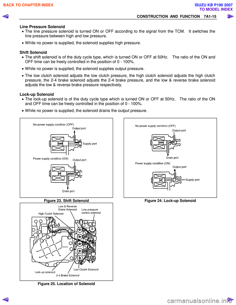
Line Pressure Solenoid • The line pressure solenoid is turned ON or OFF according to the signal from the TCM. It switches the
line pressure between high and low pressure.
• While no power is supplied, the solenoid supplies high pressure.
Shift Solenoid • The shift solenoid is of the duty cycle type, which is turned ON or OFF at 50Hz. The ratio of the ON and
OFF time can be freely controlled in the position of 0 - 100%.
• While no power is supplied, the solenoid supplies output pressure.
• The low clutch solenoid adjusts the low clutch pressure, the high clutch solenoid adjusts the high clutch
pressure, the 2-4 brake solenoid adjusts the 2-4 brake pressure, and the low & reverse brake solenoid
adjusts the low & reverse brake pressure respectively.
Lock-up Solenoid • The lock-up solenoid is of the duty cycle type which is turned ON or OFF at 50Hz. The ratio of the ON
and OFF time can be freely controlled in the position of 0 - 100%.
• While no power is supplied, the solenoid drains the output pressure.
Figure 23. Shift Solenoid Figure 24. Lock-up Solenoid
Figure 25. Location of Solenoid
BACK TO CHAPTER INDEX
TO MODEL INDEX
ISUZU KB P190 2007
Page 4255 of 6020

7A1-16 CONSTRUCTION AND FUNCTION
Control Valve Fail-safe Function • To prevent interlocking due to engagement of more than three clutches and brakes at the same time, the
2-4 brake fail-safe valve A and B, and the low & reverse brake fail-safe valve A and B are provided.
• When oil pressure is generated in the high clutch and the low clutch, the 2-4 brake solenoid is turned ON
to drain the oil pressure applied to the 2-4 brake.
• When oil pressure is generated in the high clutch or 2-4 brake, the low & reverse brake solenoid is turned
ON to drain the oil pressure applied to the low & reverse brake.
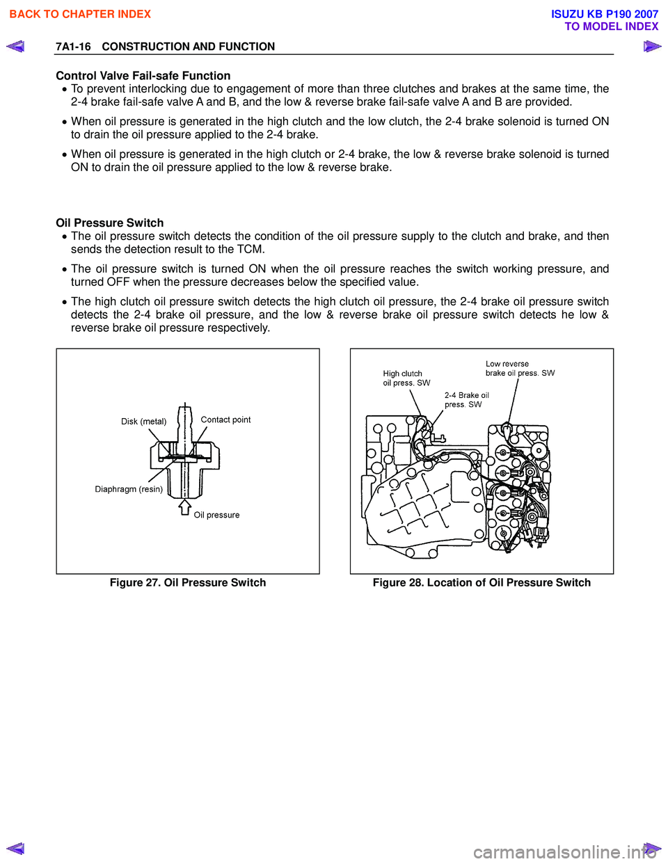
Oil Pressure Switch • The oil pressure switch detects the condition of the oil pressure supply to the clutch and brake, and then
sends the detection result to the TCM.
• The oil pressure switch is turned ON when the oil pressure reaches the switch working pressure, and
turned OFF when the pressure decreases below the specified value.
• The high clutch oil pressure switch detects the high clutch oil pressure, the 2-4 brake oil pressure switch
detects the 2-4 brake oil pressure, and the low & reverse brake oil pressure switch detects he low &
reverse brake oil pressure respectively.
Figure 27. Oil Pressure Switch Figure 28. Location of Oil Pressure Switch
BACK TO CHAPTER INDEX
TO MODEL INDEX
ISUZU KB P190 2007
Page 4270 of 6020

CONSTRUCTION AND FUNCTION 7A1-31
As a result, the lock-up piston is fitted slowly to the converter cover under pressure securing smooth lock-
up engagement.
Figure 51. Lock-up Control
DIRECT ELECTRIC SHIFT CONTROL (DESC)
Feature
• Based on each switch signal (low & reverse brake pressure, 2-4 brake pressure & high clutch pressure)
and each sensor signal (turbine sensor, speed sensor, engine speed signal & APP position signal), the
duty cycle type solenoid adjusts the clutch pressure to match the engine load and vehicle travel
conditions. Controlling the engagement and disengagement of the clutch and brake pressure is directly
and accurately controlled via TCM, which is different to the previous accumulator type.
Operation
• Instead of the previous system (on/off type of shift solenoid and shift valve), the combination of the duty
cycle type solenoid and the amplifier (Amp) valve are used to adjust the clutch pressure to match the
engine load and vehicle travel conditions, based on the signal from the TCM. Also, the pressure switch
provided in the oil passage of the control valve transmits the oil pressure condition (at that time) to TCM,
enabling the engagement and disengagement control of the clutch and brake to be directly and finely
carried out.
• When the gear is shifted from the 2nd to 3rd, 3rd to 4th (O/D), 4th (O/D) to 3rd and 3rd to 2nd, the clutch
pressures on the engagement side and disengagement side are simultaneously controlled.
As a result, engine racing or clutch drag is prevented which enables a smooth and quick shift response.
BACK TO CHAPTER INDEX
TO MODEL INDEX
ISUZU KB P190 2007