2007 ISUZU KB P190 ESP
[x] Cancel search: ESPPage 5885 of 6020
11A-34 IMMOBILIZER CONTROL SYSTEM (4JK1/4JJ1/HFV6)
DTC B0014
Description
When the transponder key authentication is completed,
the ICU begins authentication of the ECM. The ECM
transmits a specific request signal to the ICU and the
ICU sends back a response signal to the ECM. Both
communication signals are carried out via a controller
area network (CAN) communication bus. If the ICU
receives a wrong request signal from the ECM, this
DTC will set.
Condition for Running the DTC • The ignition switch is ON.
Condition for Setting the DTC • The ICU detects a wrong request signal from the ECM. Action Taken When the DTC Sets
• The engine will fail to run if the fault occurs before starting the engine.
Condition for Clearing the DTC • A current DTC clears once ignition cycle has occurred without the fault recurring.
• A history DTC will clear after 50 consecutive ignition cycles, if the condition for malfunction is no
longer present.
• Use a scan tool to clear the DTC.
Diagnostic Aids • Non-programmed ECM may set this DTC.
• If the ECM is transferred (swapped) from another vehicle, this DTC will set.
Circuit/ System Testing DTC B0014
Step Action Value(s)Yes No
1 Did you perform the Diagnostic System Check -
Immobilizer Controls? —
Go to Step 2 Go to Diagnostic
System Check - Immobilizer
Controls
2 1. Install a scan tool.
2. Turn OFF the ignition for 30 seconds.
3. Turn ON the ignition, with the engine OFF.
4. Monitor the DTC Information with a scan tool.
Does the DTC fail this ignition? —
Go to Step 3 Go to Diagnostic
Aids
3 Program immobilizer security information into the
ECM. Refer to Resetting and Programming
Guidelines in this section.
Did you complete the programming? —
Go to Step 4
—
41. Clear the DTCs with a scan tool.
2. Turn OFF the ignition for 30 seconds.
3. Turn ON the ignition.
Did the DTC fail this ignition? —
Go to Step 3 Go to Step 5
5 Observe the DTC Information with a scan tool.
Are there any DTCs that you have not diagnosed? —
Go to DTC List System OK
BACK TO CHAPTER INDEX
TO MODEL INDEX
ISUZU KB P190 2007
Page 5886 of 6020
IMMOBILIZER CONTROL SYSTEM (4JK1/4JJ1/HFV6) 11A-35
DTC U0100
Circuit Description
When the transponder key authentication is completed,
the ICU begins authentication of the ECM. The ECM
transmits a specific request signal to the ICU and the
ICU sends back a response signal to the ECM. Both
communication signals are carried out via a controller
area network (CAN) communication bus. The ICU
monitors CAN operational status by expecting a
constant flow of messages from the ECM. If the ICU
fails to send an expected message to the ECM, this
DTC will set.
Condition for Setting the DTC • The ICU detects that the CAN Bus OFF status. Action Taken When the DTC Sets
• The engine will fail to run if the fault occurs before starting the engine.
Condition for Clearing the DTC • A current DTC clears once ignition cycle has occurred without the fault recurring.
• A history DTC will clear after 50 consecutive ignition cycles, if the condition for malfunction is no
longer present.
• Use a scan tool to clear the DTC.
Diagnostic Aids • Electromagnetic interference may affect intermittent condition.
• Any communication fault with the ECM may set this DTC.
Circuit/ System Testing DTC U0100
Step Action Value(s)Yes No
1 Did you perform the Diagnostic System Check -
Immobilizer Controls? —
Go to Step 2 Go to Diagnostic
System Check - Immobilizer
Controls
2 1. Install a scan tool.
2. Turn OFF the ignition for 30 seconds.
3. Turn ON the ignition, with the engine OFF.
4. Select the Engine in the system selection menu.
5. Attempt to communicate with the ECM via the Engine Data table.
Does the scan tool communicate with the ECM? —
Go to Step 3 Go to Diagnostic
System Check -
Engine Controls
3 Monitor the ECM DTC Information with a scan tool.
Is DTC U0001 set? —Go to DTC U0001 in
Engine Control Section Go to Step 4
4 Refer to Scan Tool Does Not Communicate with
The CAN Device in this section.
Did you complete the action? —
Go to Step 5
—
51. Clear the DTCs with a scan tool.
2. Turn OFF the ignition for 30 seconds.
3. Turn ON the ignition.
Did the DTC fail this ignition? —
Go to Step 2 Go to Step 6
6 Observe the DTC Information with a scan tool.
Are there any DTCs that you have not diagnosed? —
Go to DTC List System OK
BACK TO CHAPTER INDEX
TO MODEL INDEX
ISUZU KB P190 2007
Page 5887 of 6020
11A-36 IMMOBILIZER CONTROL SYSTEM (4JK1/4JJ1/HFV6)
Resetting and Programming
Resetting and Programming Guidelines
Notice:The security information must be programmed
when the ICU, ECM, PIM or transponder key(s) is
replaced, or transponder key(s) is added.
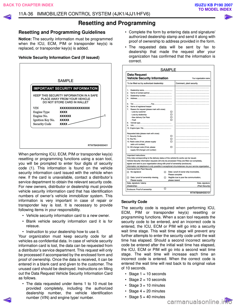
Vehicle Security Information Card (If issued)
When performing ICU, ECM, PIM or transponder key(s)
resetting or programming functions using a scan tool,
you will be prompted to enter four digits of security
code (1). This information is found on the vehicle
security information card issued with the vehicle when
new. If the card is unavailable, contact a distributor’s
service department to obtain the relevant security code.
For new owners, distributor or dealership must provide
vehicle security information card that has identification
numbers of owner’s vehicle immobilizer system. This
information is very important in case of repair or
transponder key is lost. It is necessary to provide
following items in your responsibility.
• Vehicle security information card to a new owner.
• Blank vehicle security information card it is for reissue.
• Instruction to your dealership how to use it.
Your organization must keep security code for all
vehicles as confidential data. In case of vehicle security
information card is lost, the data can be requested from
a distributor’s service department. This request will only
be processed if accompanied by the enclosed form and
proof of ownership. Once the data is received, it can be
entered in a blank card and given to the customer. The
unused card should be destroyed. Instructions on filling
out the Data Request Vehicle Security Information Card
as follows.
• The data requested under items 1 to 10 must be provided completely, including the authorized
dealership number, the vehicle identification
number (VIN) and engine type/ number. • Complete the form by entering data and signature/
authorized dealership stamp and send it along with
proof of ownership to address provided in the form.
• The requested data will be sent by fax to dealership that made the request after your
organization has confirmed that the information is
correct.
Security Code
The security code is required when performing ICU,
ECM, PIM or transponder key(s) resetting or
programming functions. When a scan tool requests the
security code to be entered, and an incorrect code is
entered, the ICU, ECM or PIM will go into a security
wait time stage. This wait time stage will prevent any
further attempts to enter the security code until the wait
time has elapsed. Should a second incorrect security
code be entered after the initial wait time has elapsed,
the ICU, ECM or PIM will go into a second wait time
stage. The wait time will increase each time an
incorrect code is entered. When the correct code is
entered the wait time will rest back to its original value
of 10 seconds.
• Stage 1 = 10 seconds
• Stage 2 = 10 seconds
• Stage 3 = 10 minutes
• Stage 4 = 20 minutes
• Stage 5 = 40 minutes
RTW7BASH000401
KEEP THIS SECURITY INFORMATION IN A SAFE PLACE AWAY FROM YOUR VEHICLEDO NOT STORE CARD IN WALLET
1
SAMPLE
RTW7BAMH000101
Your organization name
To be filled out by authorized dealership: Comment, plant security
1. Dealership name.......................................................... ....................................................................
....................................................................
....................................................................
....................................................................
....................................................................
....................................................................
....................................................................
....................................................................
.................................................................... ....................................................................
....................................................................
....................................................................
....................................................................
....................................................................
2. Name of contact partner.............................................
6. Name of registered keeper
7. Reason for request (please mark with cross)
3. Dealership number......................................................
4. Address.......................................................................
8. Vehicle type................................................................
9. VIN................................................................................
10. Engine type / No.........................................................
11. Security Code :
12. Key No. :
13. Radio code (if lost, please supply radio unit number)
14. CD-changer code (if lost, please
supply CD-changer unit number)
Requested data (please mark with cross)
5. Tel:....................................Fax....................................
.....................................................................................
- Loss by customer
- Loss by dealership
- New delivery Car Pass
- Theft
Important Instructions:
Comments form Plant Security
Data, signature / stamp Data, signature
(Dealership) (Plant Security)
Enclosure: Proof of ownership Only data corresponding to the delivery status of the vehicle Ex works can be Issued.
Vehicle Security Information requests will only be processed if they are filled out completely,
signed and sent to your organization along with proof of ownership (enclosure).
Information via telephone is only possible in exceptional circumstances via your service organization.
No signature Data / proof of owner ship incomplete,
Please complete
Data / proof of ownership missing,
Please supply Illegible due to poor fax communication,
please resend
SAMPLE
BACK TO CHAPTER INDEX TO MODEL INDEX
ISUZU KB P190 2007
Page 5896 of 6020
IMMOBILIZER CONTROL SYSTEM (4JK1/4JJ1/HFV6) 11A-45
Description and Operation
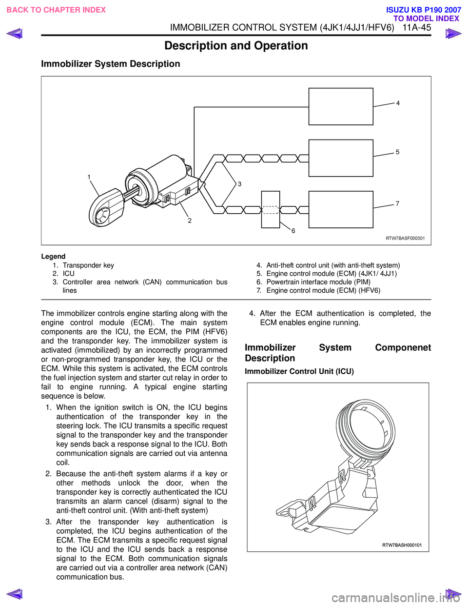
Immobilizer System Description
Legend1. Transponder key
2. ICU
3. Controller area network (CAN) communication bus lines 4. Anti-theft control unit (with anti-theft system)
5. Engine control module (ECM) (4JK1/ 4JJ1)
6. Powertrain interface module (PIM)
7. Engine control module (ECM) (HFV6)
The immobilizer controls engine starting along with the
engine control module (ECM). The main system
components are the ICU, the ECM, the PIM (HFV6)
and the transponder key. The immobilizer system is
activated (immobilized) by an incorrectly programmed
or non-programmed transponder key, the ICU or the
ECM. While this system is activated, the ECM controls
the fuel injection system and starter cut relay in order to
fail to engine running. A typical engine starting
sequence is below.
1. When the ignition switch is ON, the ICU begins authentication of the transponder key in the
steering lock. The ICU transmits a specific request
signal to the transponder key and the transponder
key sends back a response signal to the ICU. Both
communication signals are carried out via antenna
coil.
2. Because the anti-theft system alarms if a key or other methods unlock the door, when the
transponder key is correctly authenticated the ICU
transmits an alarm cancel (disarm) signal to the
anti-theft control unit. (With anti-theft system)
3. After the transponder key authentication is completed, the ICU begins authentication of the
ECM. The ECM transmits a specific request signal
to the ICU and the ICU sends back a response
signal to the ECM. Both communication signals
are carried out via a controller area network (CAN)
communication bus. 4. After the ECM authentication is completed, the
ECM enables engine running.
Immobilizer System Componenet
Description
Immobilizer Control Unit (ICU)
RTW7BASH000101
BACK TO CHAPTER INDEX TO MODEL INDEX
ISUZU KB P190 2007
Page 5897 of 6020
11A-46 IMMOBILIZER CONTROL SYSTEM (4JK1/4JJ1/HFV6)
The ICU is installed to the steering lock. The ICU
controls the immobilizer system by authentication of the
transponder key and the ECM. An antenna coil is a part
of the ICU and it is located around steering key lock
cylinder. An antenna coil is energized when the ICU is
performing an authentication of the transponder key.
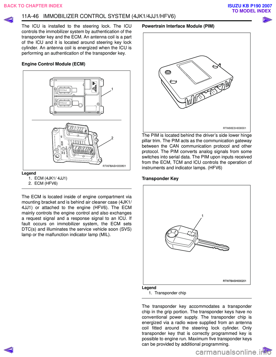
Engine Control Module (ECM)
Legend 1. ECM (4JK1/ 4JJ1)
2. ECM (HFV6)
The ECM is located inside of engine compartment via
mounting bracket and is behind air cleaner case (4JK1/
4JJ1) or attached to the engine (HFV6). The ECM
mainly controls the engine control and also exchanges
a request signal and a response signal to an ICU. If
fault occurs on immobilizer system, the ECM sets
DTC(s) and illuminates the service vehicle soon (SVS)
lamp or the malfunction indicator lamp (MIL). Powertrain Interface Module (PIM)
The PIM is located behind the driver’s side lower hinge
pillar trim. The PIM acts as the communication gateway
between the CAN communication protocol and other
protocol. The PIM converts analog signals from some
switches into serial data. The PIM upon inputs received
from the ECM, TCM and ICU controls the operation of
instruments and indicator lamps. (HFV6)
Transponder Key
Legend 1. Transponder chip
The transponder key accommodates a transponder
chip in the grip portion. The transponder keys have no
conventional power supply. The transponder chip is
energized via a radio wave supplied from an antenna
coil fitted around the steering lock cylinder. Only
transponder key that is correctly programmed key is
possible to engine run. Maximum five transponder keys
can be provided by additional programming.
RTW7BASH000201
1
BACK TO CHAPTER INDEX TO MODEL INDEX
ISUZU KB P190 2007
Page 5903 of 6020
IMMOBILIZER SYSTEM (C24SE, 4JA1-T) 11A-5
What happens without proper transponder
operation?
One of the function of transponder is to deactivate or
activate starter function. lf the proper transponder is not
used, starter cannot be operated. Because starter rela
y
stays off, cranking engine is not possible.
After the starter relay is activated, transponder signal
triggers to let lCU calculate by transponder address
signal and immobilizer algorithm.
W hen the result matches with necessary condition, it
makes injector power source be activated.
If transponder does not send correct signal, lCU and
ECM do not activate injector system on.
Therefore the vehicle cannot be operated.
No proper transponder is available, what
should be done for the system?
W hen any proper transponder is not available, a new
transponder should be programmed. Up to 5
transponders can be provided with a scan tool (Tech-2)
and by proper procedure.
In addition to the absence of proper transponder, it ma
y
happen particular secret code to the particular vehicle is
missing. ln this case, the secret code must be provided
by your organization.
Otherwise transponder cannot be programmed in an
y
way.
lf the essential for a scan tool (Tech-2) for programming
and proper software for Tech-2 are not available, there
is no permanent way to fix system. Temporary replace
with new ECM, new ICU and new transponder without
any secret code can make the system be deactivated,
but it does not last long. Such a replacement does not
solve any condition. Even after replacement, the system
is activated automatically in short time and then no
operation of the vehicle can be made in any way.
Tech-2 should be provided in your organization.
Caution to the operation
lf an attempt is made to start the engine while the
immobilizer system is activated, the check engine lamp
flashes and the engine will not start.
Summary of operation
Switch on: Set the ignition and starter switch to OFF.
(Activate)
Switch off: Set the ignition and starter switch to ON b
y
using the transponder key. (Deactivate)
What your organization should provide for
your customer
•
••
•
Car Pass
For a new owner, your dealership must hand Car Pass
card, which has identification numbers of new owner's
vehicle immobilizer system. This information is ver
y
important in case of repair or lost of transponder.
The followings are necessary items provided by you
r
responsibility.
1) Car pass with identification for a new owner
2) Blank car pass card when it is for reissue
3) Instruction to dealers how to use car pass card
•
••
•
Security code management
Your organization must keep security codes for all
vehicles as confidential data. Once the security codes
are lost, anybody who have the security code can
access immobilizer system. Your organization has
responsibility of any missing vehicles caused by stolen
security code.
•
••
•
Essential tool (Scan tool : Tech-2)
Your dealership must have Tech-2, and Tech-2 updated
software for immobilizer system.
BACK TO CHAPTER INDEX TO MODEL INDEX
ISUZU KB P190 2007
Page 5913 of 6020
IMMOBILIZER SYSTEM (C24SE, 4JA1-T) 11A-15
Important Instructions
Only data corresponding to the delivery status of the
vehicle can be issued. Car pass data requests will onl
y
be processed if the first column is filled out completely.
Signed and sent to your organization along with proof of
ownership.
Information via telephone is only possible in exceptional
circumstances via your service organization.
As for the delivery of new vehicles, the customer must
be informed about all features of the car pass that are
relevant to vehicle security, for example, that the ca
r
pass card should be kept in a safe place(not in the
vehicle) and should be presented when an authorized
your organization name workshop is visited, The exact
phrasing can be found in the relevant Owner's Manual.
BACK TO CHAPTER INDEX
TO MODEL INDEX
ISUZU KB P190 2007
Page 5926 of 6020
11A-28 IMMOBILIZER SYSTEM (C24SE, 4JA1-T)
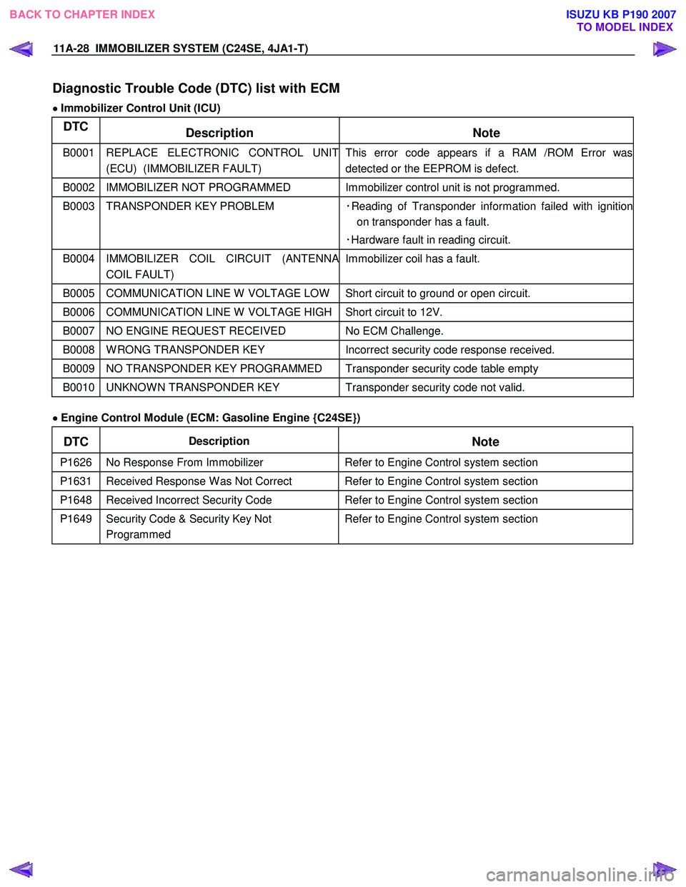
Diagnostic Trouble Code (DTC) list with ECM
•
••
•
Immobilizer Control Unit (ICU)
DTC
Description Note
B0001 REPLACE ELECTRONIC CONTROL UNIT
(ECU) (IMMOBILIZER FAULT) This error code appears if a RAM /ROM Error was
detected or the EEPROM is defect.
B0002 IMMOBILIZER NOT PROGRAMMED Immobilizer control unit is not programmed.
B0003 TRANSPONDER KEY PROBLEM ・Reading of Transponder information failed with ignition
on transponder has a fault.
・Hardware fault in reading circuit.
B0004 IMMOBILIZER COIL CIRCUIT (ANTENNA
COIL FAULT) Immobilizer coil has a fault.
B0005 COMMUNICATION LINE W VOLTAGE LOW Short circuit to ground or open circuit.
B0006 COMMUNICATION LINE W VOLTAGE HIGH Short circuit to 12V.
B0007 NO ENGINE REQUEST RECEIVED
No ECM Challenge.
B0008 W RONG TRANSPONDER KEY Incorrect security code response received.
B0009 NO TRANSPONDER KEY PROGRAMMED Transponder security code table empty
B0010 UNKNOW N TRANSPONDER KEY Transponder security code not valid.
•
••
•
Engine Control Module (ECM: Gasoline Engine {C24SE})
DTC Description
Note
P1626 No Response From Immobilizer Refer to Engine Control system section
P1631 Received Response W as Not Correct Refer to Engine Control system section
P1648 Received Incorrect Security Code Refer to Engine Control system section
P1649 Security Code & Security Key Not
Programmed Refer to Engine Control system section
BACK TO CHAPTER INDEX TO MODEL INDEX
ISUZU KB P190 2007