2007 ISUZU KB P190 vacuum
[x] Cancel search: vacuumPage 2237 of 6020
ENGINE DRIVEABILITY AND EMISSIONS 6E–67
GENERAL SERVICE INFORMATION
Aftermarket Electrical and Vacuum
Equipment
Aftermarket (add-on) electrical and vacuum equipment
is defined as any equipment which connects to the
vehicle's electrical or vacuum systems that is installed
on a vehicle after it leaves the factory. No allowances
have been made in the vehicle design for this type of
equipment.
NOTE: No add-on vacuum equipment should be added
to this vehicle.
NOTE: Add-on electrical equipment must only be
connected to the vehicle's electrical system at the
battery (power and ground).
Add-on electrical equipment, even when installed to
these guidelines, may still cause the electric system to
malfunction. This may also include equipment not
connected to the vehicle electrical system such as
portable telephones and radios. Therefore, the first step
in diagnosing any electric problem is to eliminate all
aftermarket electrical equipment from the vehicle. After
this is done, if the problem still exists, it may be
diagnosed in the normal manner.
Electrostatic Discharge Damage
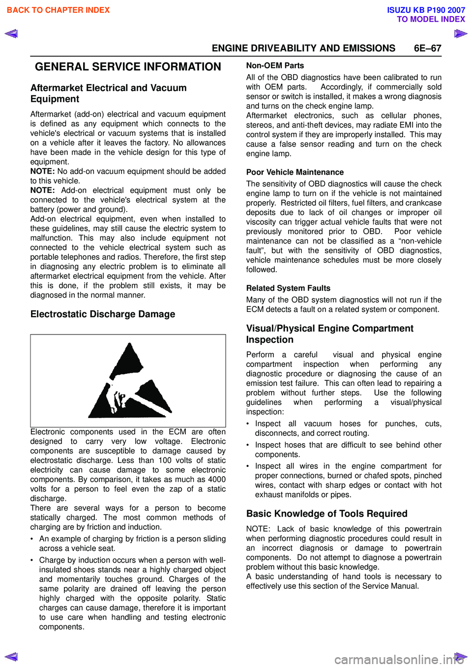
Electronic components used in the ECM are often
designed to carry very low voltage. Electronic
components are susceptible to damage caused by
electrostatic discharge. Less than 100 volts of static
electricity can cause damage to some electronic
components. By comparison, it takes as much as 4000
volts for a person to feel even the zap of a static
discharge.
There are several ways for a person to become
statically charged. The most common methods of
charging are by friction and induction.
• An example of charging by friction is a person sliding across a vehicle seat.
• Charge by induction occurs when a person with well- insulated shoes stands near a highly charged object
and momentarily touches ground. Charges of the
same polarity are drained off leaving the person
highly charged with the opposite polarity. Static
charges can cause damage, therefore it is important
to use care when handling and testing electronic
components. Non-OEM Parts
All of the OBD diagnostics have been calibrated to run
with OEM parts. Accordingly, if commercially sold
sensor or switch is installed, it makes a wrong diagnosis
and turns on the check engine lamp.
Aftermarket electronics, such as cellular phones,
stereos, and anti-theft devices, may radiate EMI into the
control system if they are improperly installed. This may
cause a false sensor reading and turn on the check
engine lamp.
Poor Vehicle Maintenance
The sensitivity of OBD diagnostics will cause the check
engine lamp to turn on if the vehicle is not maintained
properly. Restricted oil filters, fuel filters, and crankcase
deposits due to lack of oil changes or improper oil
viscosity can trigger actual vehicle faults that were not
previously monitored prior to OBD. Poor vehicle
maintenance can not be classified as a “non-vehicle
fault”, but with the sensitivity of OBD diagnostics,
vehicle maintenance schedules must be more closely
followed.
Related System Faults
Many of the OBD system diagnostics will not run if the
ECM detects a fault on a related system or component.
Visual/Physical Engine Compartment
Inspection
Perform a careful visual and physical engine
compartment inspection when performing any
diagnostic procedure or diagnosing the cause of an
emission test failure. This can often lead to repairing a
problem without further steps. Use the following
guidelines when performing a visual/physical
inspection:
• Inspect all vacuum hoses for punches, cuts, disconnects, and correct routing.
• Inspect hoses that are difficult to see behind other components.
• Inspect all wires in the engine compartment for proper connections, burned or chafed spots, pinched
wires, contact with sharp edges or contact with hot
exhaust manifolds or pipes.
Basic Knowledge of Tools Required
NOTE: Lack of basic knowledge of this powertrain
when performing diagnostic procedures could result in
an incorrect diagnosis or damage to powertrain
components. Do not attempt to diagnose a powertrain
problem without this basic knowledge.
A basic understanding of hand tools is necessary to
effectively use this section of the Service Manual.
BACK TO CHAPTER INDEX
TO MODEL INDEX
ISUZU KB P190 2007
Page 2279 of 6020
ENGINE DRIVEABILITY AND EMISSIONS 6E–109
• The fuel injector(s).
4. Fuel pressure that drops off during acceleration, cruise, or hard cornering may case a lean condition.
A lean condition can cause a loss of power, surging,
or misfire. A lean condition can be diagnosed using a
Tech 2 Scan Tool.
Following are applicable to the vehicle with
closed Loop System:
If an extremely lean condition occurs, the oxygen
sensor(s) will stop toggling. The oxygen sensor
output voltage(s) will drop below 500 mV. Also, the
fuel injector pulse width will increase.
Important: Make sure the fuel system is not
operating in the “Fuel Cut-Off Mode.”
When the engine is at idle, the manifold pressure is
low (high vacuum). This low pressure (high vacuum)
is applied to the fuel pressure regulator diaphragm.
The low pressure (high vacuum) will offset the
pressure being applied to the fuel pressure regulator
diaphragm by the spring inside the fuel pressure
regulator. When this happens, the result is lower fuel
pressure. The fuel pressure at idle will vary slightly
as the barometric pressure changes, but the fuel
pressure at idle should always be less than the fuel
pressure noted in step 2 with the engine OFF.
16.Check the spark plug associated with a particular
fuel injector for fouling or saturation in order to
determine if that particular fuel injector is leaking. If
checking the spark plug associated with a particular
fuel injector for fouling or saturation does not
determine that a particular fuel injector is leaking,
use the following procedure:
• Remove the fuel rail, but leave the fuel lines and injectors connected to the fuel rail. Refer to Fuel
Rail Assembly in On-Vehicle Service .
• Lift the fuel rail just enough to leave the fuel injector nozzles in the fuel injector ports.
Caution: In order to reduce the risk of fire and
personal injury that may result from fuel
spraying on the engine, verify that the fuel rail is
positioned over the fuel injector ports and verify
that the fuel injector retaining clips are intact.
• Pressurize the fuel system by connecting a 20 amp fused jumper between B+ and the fuel
pump relay connector.
• Visually and physically inspect the fuel injector nozzles for leaks.
17.A rich condition may result from the fuel pressure being above 376 kPa (55 psi). A rich condition may
cause a 45 to set. Driveability conditions associated with rich conditions can include hard starting
(followed by black smoke) and a strong sulfur smell
in the exhaust.
20.This test determines if the high fuel pressure is due to a restricted fuel return line or if the high fuel
pressure is due to a faulty fuel pressure regulator.
21.A lean condition may result from fuel pressure below 333 kPa (48 psi). A lean condition may cause a 44 to
set. Driveability conditions associated with lean
conditions can include hard starting (when the
engine is cold), hesitation, poor driveability, lack of
power, surging, and misfiring.
22.Restricting the fuel return line causes the fuel pressure to rise above the regulated fuel pressure.
Command the fuel pump ON with the scan tool. The
fuel pressure should rise above 376 kPa (55 psi) as
the fuel return line becomes partially closed.
NOTE: Do not allow the fuel pressure to exceed 414
kPa (60 psi). Fuel pressure in excess of 414 kPa (60
psi) may damage the fuel pressure regulator. Caution: To reduce the risk of fire and personal
injury:
• It is necessary to relieve fuel system pressure before connecting a fuel pressure gauge.
Refer to Fuel Pressure Relief Procedure,
below.
• A small amount of fuel may be released when disconnecting the fuel lines. Cover fuel line
fittings with a shop towel before
disconnecting, to catch any fuel that may leak
out. Place the towel in an approved container
when the disconnect is completed.
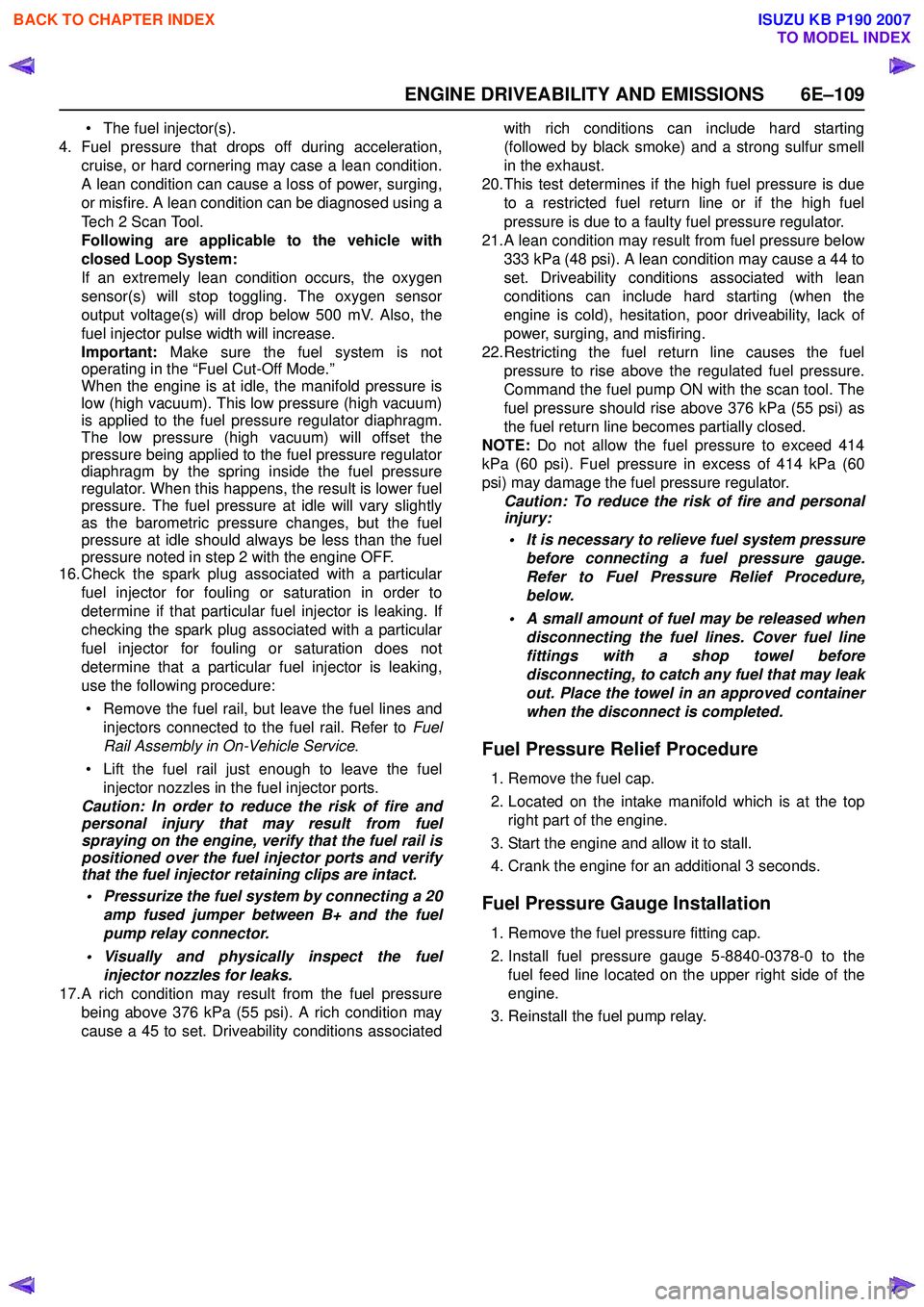
Fuel Pressure Relief Procedure
1. Remove the fuel cap.
2. Located on the intake manifold which is at the top right part of the engine.
3. Start the engine and allow it to stall.
4. Crank the engine for an additional 3 seconds.
Fuel Pressure Gauge Installation
1. Remove the fuel pressure fitting cap.
2. Install fuel pressure gauge 5-8840-0378-0 to the fuel feed line located on the upper right side of the
engine.
3. Reinstall the fuel pump relay.
BACK TO CHAPTER INDEX
TO MODEL INDEX
ISUZU KB P190 2007
Page 2280 of 6020
6E–110 ENGINE DRIVEABILITY AND EMISSIONS
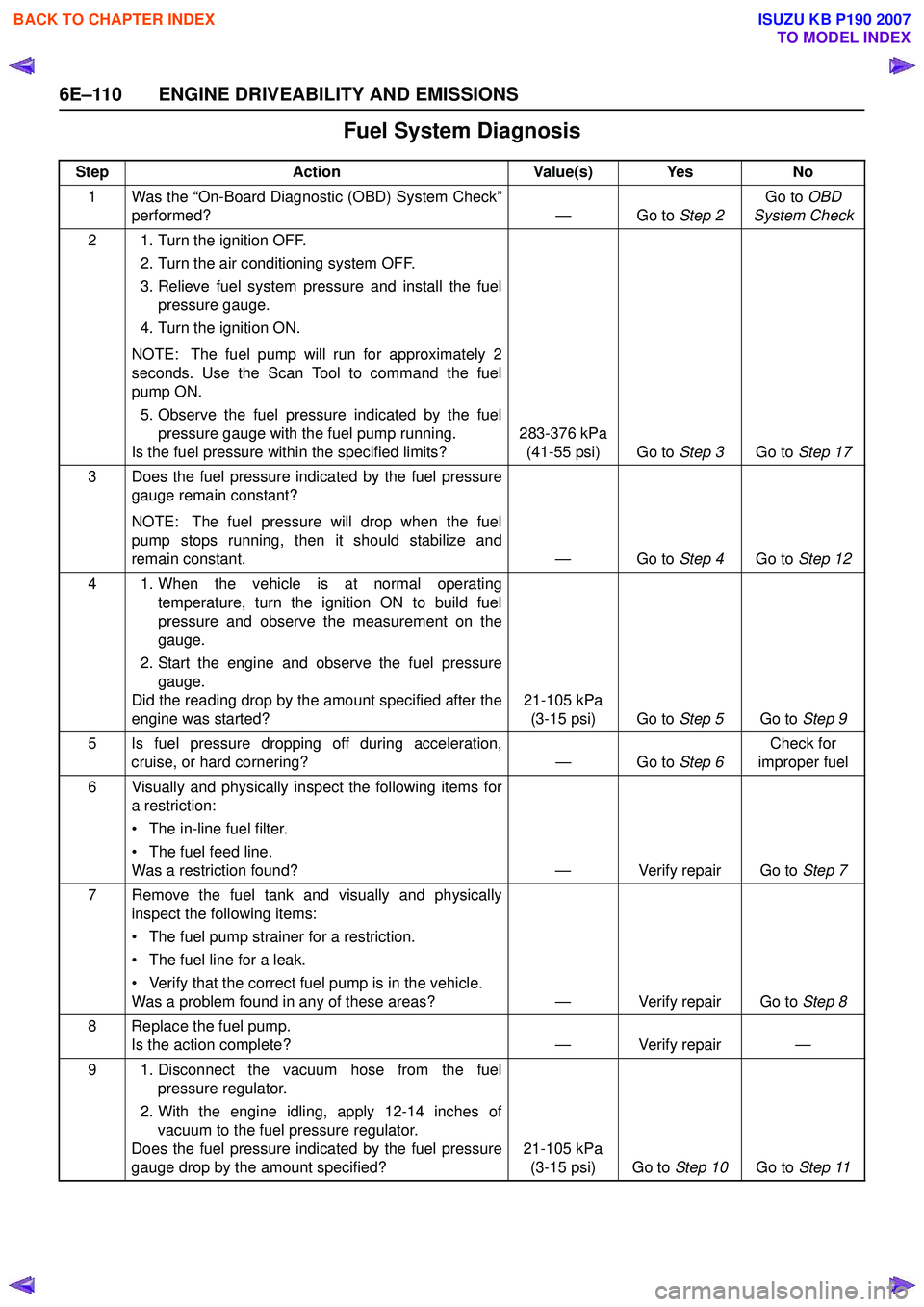
Fuel System Diagnosis
StepAction Value(s) Yes No
1 Was the “On-Board Diagnostic (OBD) System Check” performed? — Go to Step 2Go to
OBD
System Check
2 1. Turn the ignition OFF. 2. Turn the air conditioning system OFF.
3. Relieve fuel system pressure and install the fuel pressure gauge.
4. Turn the ignition ON.
NOTE: The fuel pump will run for approximately 2
seconds. Use the Scan Tool to command the fuel
pump ON.
5. Observe the fuel pressure indicated by the fuel pressure gauge with the fuel pump running.
Is the fuel pressure within the specified limits? 283-376 kPa
(41-55 psi) Go to Step 3Go to Step 17
3 Does the fuel pressure indicated by the fuel pressure gauge remain constant?
NOTE: The fuel pressure will drop when the fuel
pump stops running, then it should stabilize and
remain constant. — Go to Step 4Go to Step 12
4 1. When the vehicle is at normal operating temperature, turn the ignition ON to build fuel
pressure and observe the measurement on the
gauge.
2. Start the engine and observe the fuel pressure gauge.
Did the reading drop by the amount specified after the
engine was started? 21-105 kPa
(3-15 psi) Go to Step 5Go to Step 9
5 Is fuel pressure dropping off during acceleration, cruise, or hard cornering? — Go to Step 6Check for
improper fuel
6 Visually and physically inspect the following items for a restriction:
• The in-line fuel filter.
• The fuel feed line.
Was a restriction found? — Verify repair Go to Step 7
7 Remove the fuel tank and visually and physically inspect the following items:
• The fuel pump strainer for a restriction.
• The fuel line for a leak.
• Verify that the correct fuel pump is in the vehicle.
Was a problem found in any of these areas? — Verify repair Go to Step 8
8 Replace the fuel pump. Is the action complete? — Verify repair —
9 1. Disconnect the vacuum hose from the fuel pressure regulator.
2. With the engine idling, apply 12-14 inches of vacuum to the fuel pressure regulator.
Does the fuel pressure indicated by the fuel pressure
gauge drop by the amount specified? 21-105 kPa
(3-15 psi) Go to Step 10Go to Step 11
BACK TO CHAPTER INDEX
TO MODEL INDEX
ISUZU KB P190 2007
Page 2281 of 6020
ENGINE DRIVEABILITY AND EMISSIONS 6E–111
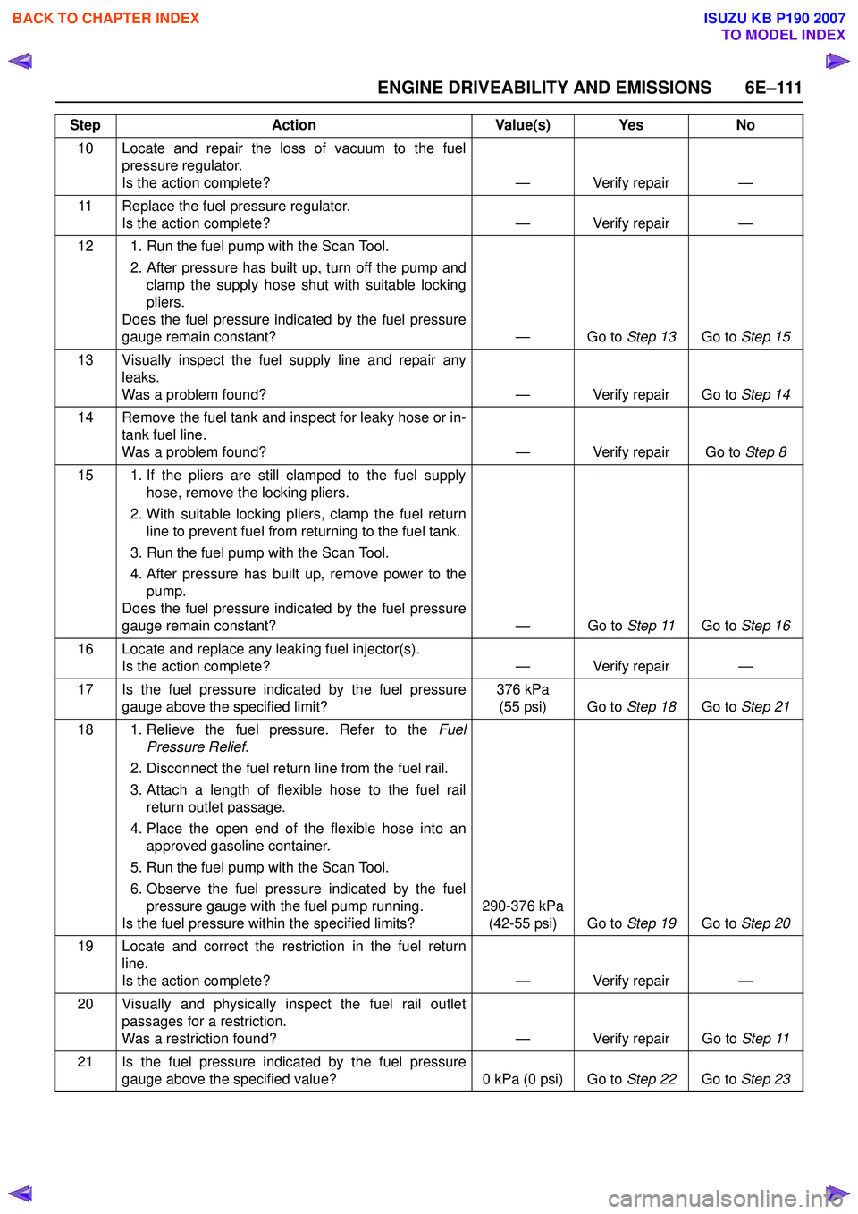
10 Locate and repair the loss of vacuum to the fuelpressure regulator.
Is the action complete? — Verify repair —
11 Replace the fuel pressure regulator. Is the action complete? — Verify repair —
12 1. Run the fuel pump with the Scan Tool. 2. After pressure has built up, turn off the pump andclamp the supply hose shut with suitable locking
pliers.
Does the fuel pressure indicated by the fuel pressure
gauge remain constant? — Go to Step 13Go to Step 15
13 Visually inspect the fuel supply line and repair any leaks.
Was a problem found? — Verify repair Go to Step 14
14 Remove the fuel tank and inspect for leaky hose or in- tank fuel line.
Was a problem found? — Verify repair Go to Step 8
15 1. If the pliers are still clamped to the fuel supply hose, remove the locking pliers.
2. With suitable locking pliers, clamp the fuel return line to prevent fuel from returning to the fuel tank.
3. Run the fuel pump with the Scan Tool.
4. After pressure has built up, remove power to the pump.
Does the fuel pressure indicated by the fuel pressure
gauge remain constant? — Go to Step 11Go to Step 16
16 Locate and replace any leaking fuel injector(s). Is the action complete? — Verify repair —
17 Is the fuel pressure indicated by the fuel pressure gauge above the specified limit? 376 kPa
(55 psi) Go to Step 18Go to Step 21
18 1. Relieve the fuel pressure. Refer to the Fuel
Pressure Relief .
2. Disconnect the fuel return line from the fuel rail.
3. Attach a length of flexible hose to the fuel rail return outlet passage.
4. Place the open end of the flexible hose into an approved gasoline container.
5. Run the fuel pump with the Scan Tool.
6. Observe the fuel pressure indicated by the fuel pressure gauge with the fuel pump running.
Is the fuel pressure within the specified limits? 290-376 kPa
(42-55 psi) Go to Step 19Go to Step 20
19 Locate and correct the restriction in the fuel return line.
Is the action complete? — Verify repair —
20 Visually and physically inspect the fuel rail outlet passages for a restriction.
Was a restriction found? — Verify repair Go to Step 11
21 Is the fuel pressure indicated by the fuel pressure gauge above the specified value? 0 kPa (0 psi) Go to Step 22Go to Step 23
Step
Action Value(s) Yes No
BACK TO CHAPTER INDEX
TO MODEL INDEX
ISUZU KB P190 2007
Page 2322 of 6020
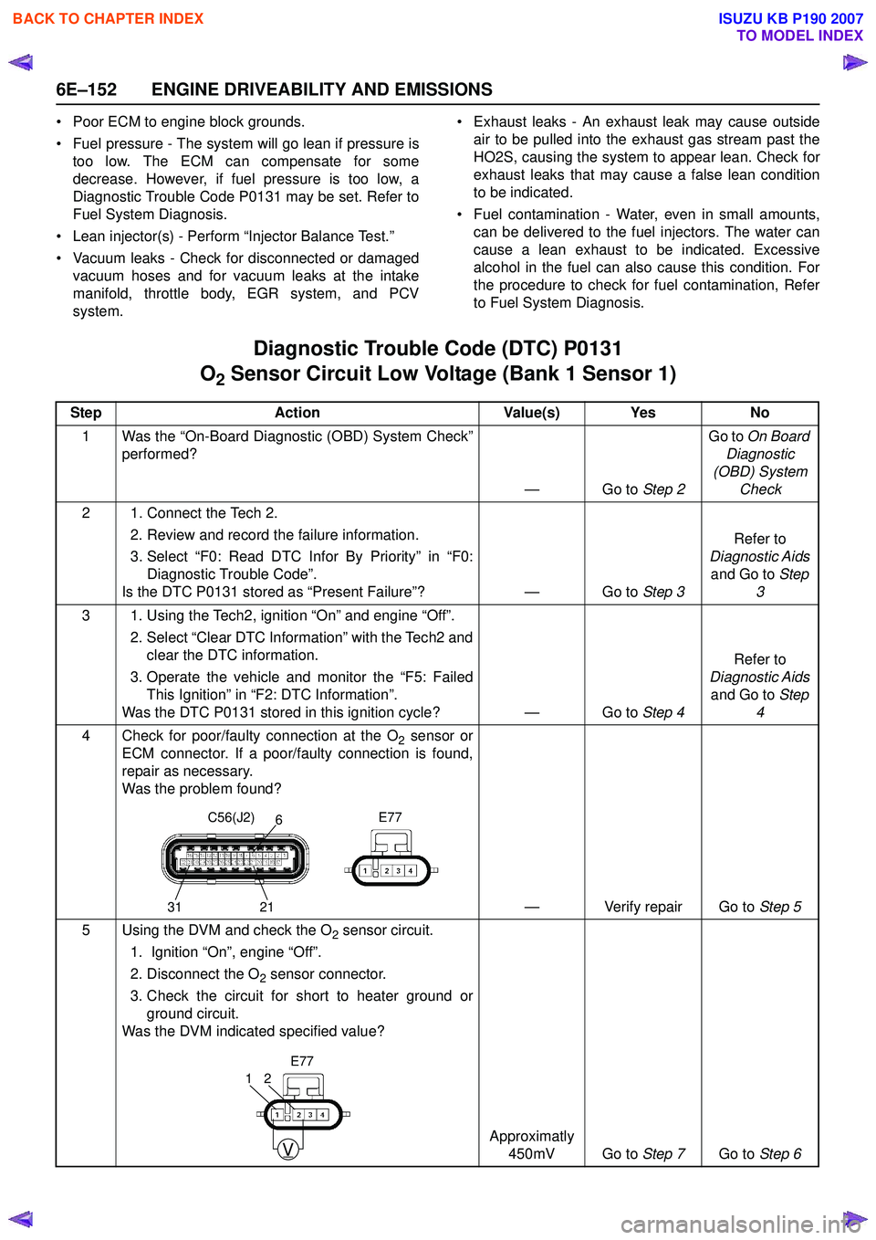
6E–152 ENGINE DRIVEABILITY AND EMISSIONS
• Poor ECM to engine block grounds.
• Fuel pressure - The system will go lean if pressure is too low. The ECM can compensate for some
decrease. However, if fuel pressure is too low, a
Diagnostic Trouble Code P0131 may be set. Refer to
Fuel System Diagnosis.
• Lean injector(s) - Perform “Injector Balance Test.”
• Vacuum leaks - Check for disconnected or damaged vacuum hoses and for vacuum leaks at the intake
manifold, throttle body, EGR system, and PCV
system. • Exhaust leaks - An exhaust leak may cause outside
air to be pulled into the exhaust gas stream past the
HO2S, causing the system to appear lean. Check for
exhaust leaks that may cause a false lean condition
to be indicated.
• Fuel contamination - Water, even in small amounts, can be delivered to the fuel injectors. The water can
cause a lean exhaust to be indicated. Excessive
alcohol in the fuel can also cause this condition. For
the procedure to check for fuel contamination, Refer
to Fuel System Diagnosis.
Diagnostic Trouble Code (DTC) P0131
O
2 Sensor Circuit Low Voltage (Bank 1 Sensor 1)
Step Action Value(s) Yes No
1 Was the “On-Board Diagnostic (OBD) System Check” performed?
—Go to Step 2Go to
On Board
Diagnostic
(OBD) System Check
2 1. Connect the Tech 2. 2. Review and record the failure information.
3. Select “F0: Read DTC Infor By Priority” in “F0: Diagnostic Trouble Code”.
Is the DTC P0131 stored as “Present Failure”? — Go to Step 3Refer to
Diagnostic Aids and Go to Step
3
3 1. Using the Tech2, ignition “On” and engine “Off”. 2. Select “Clear DTC Information” with the Tech2 andclear the DTC information.
3. Operate the vehicle and monitor the “F5: Failed This Ignition” in “F2: DTC Information”.
Was the DTC P0131 stored in this ignition cycle? — Go to Step 4Refer to
Diagnostic Aids and Go to Step
4
4 Check for poor/faulty connection at the O
2 sensor or
ECM connector. If a poor/faulty connection is found,
repair as necessary.
Was the problem found?
— Verify repair Go to Step 5
5 Using the DVM and check the O
2 sensor circuit.
1. Ignition “On”, engine “Off”.
2. Disconnect the O
2 sensor connector.
3. Check the circuit for short to heater ground or ground circuit.
Was the DVM indicated specified value?
Approximatly 450mV Go to Step 7Go to Step 6
C56(J2) E77
31 216
V
21
E77
BACK TO CHAPTER INDEX
TO MODEL INDEX
ISUZU KB P190 2007
Page 2324 of 6020
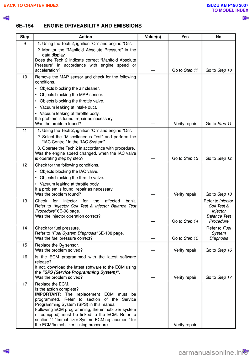
6E–154 ENGINE DRIVEABILITY AND EMISSIONS
9 1. Using the Tech 2, ignition “On” and engine “On”. 2. Monitor the “Manifold Absolute Pressure” in thedata display.
Does the Tech 2 indicate correct “Manifold Absolute
Pressure” in accordance with engine speed or
acceleration? — Go to Step 11Go to Step 10
10 Remove the MAP sensor and check for the following conditions.
• Objects blocking the air cleaner.
• Objects blocking the MAP sensor.
• Objects blocking the throttle valve.
• Vacuum leaking at intake duct.
• Vacuum leaking at throttle body.
If a problem is found, repair as necessary.
Was the problem found? — Verify repair Go to Step 11
11 1. Using the Tech 2, ignition “On” and engine “On”. 2. Select the “Miscellaneous Test” and perform the“IAC Control” in the “IAC System”.
3. Operate the Tech 2 in accordance with procedure.
Was the engine speed changed, when the IAC valve
is operating step by step? — Go to Step 13Go to Step 12
12 Check for the following conditions. • Objects blocking the IAC valve.
• Objects blocking the throttle valve.
• Vacuum leaking at throttle body.
If a problem is found, repair as necessary.
Was the problem found? — Verify repair Go to Step 13
13 Check for injector for the affected bank. Refer to “Injector Coil Test & Injector Balance Test
Procedure” 6E-98 page .
Was the injector operation correct? —Go to Step 14Refer to
Injector
Coil Test & Injector
Balance Test Procedure
14 Check for fuel pressure. Refer to “Fuel System Diagnosis” 6E-108 page.
Was the fuel pressure correct? — Go to Step 15Refer to
Fuel
System
Diagnosis
15 Replace the O
2 sensor.
Was the problem solved? — Verify repair Go to Step 16
16 Is the ECM programmed with the latest software release?
If not, download the latest software to the ECM using
the “SPS (Service Programming System)”.
Was the problem solved? — Verify repair Go to Step 17
17 Replace the ECM. Is the action complete?
IMPORTANT: The replacement ECM must be
programmed. Refer to section of the Service
Programming System (SPS) in this manual.
Following ECM programming, the immobilizer system
(if equipped) must be linked to the ECM. Refer to
section 11 “Immobilizer System-ECM replacement” for
the ECM/Immobilizer linking procedure. — Verify repair —
Step
Action Value(s) Yes No
BACK TO CHAPTER INDEX
TO MODEL INDEX
ISUZU KB P190 2007
Page 2326 of 6020
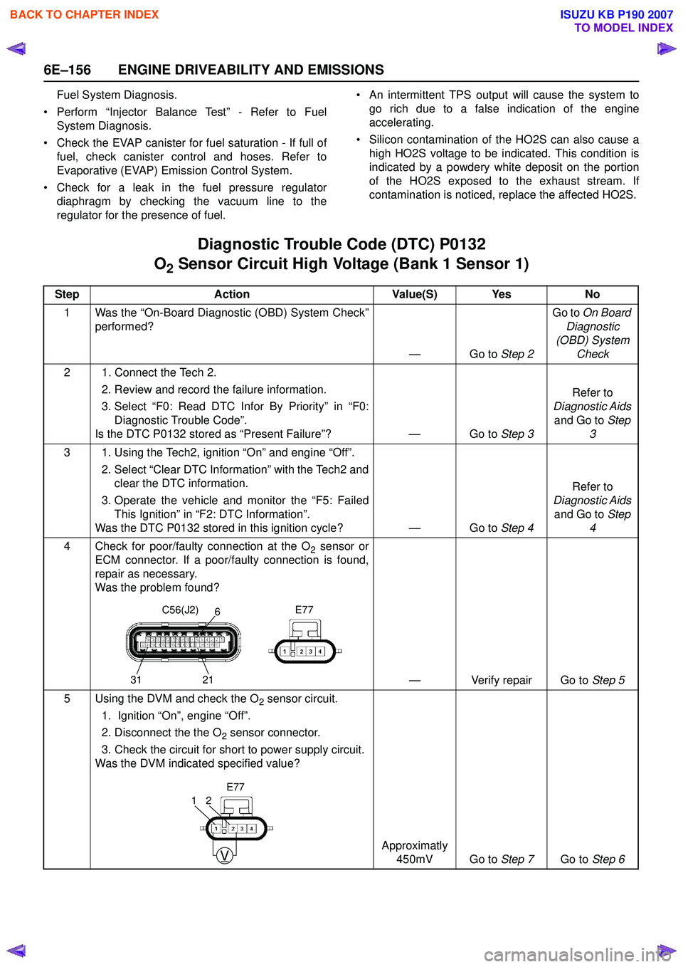
6E–156 ENGINE DRIVEABILITY AND EMISSIONS
Fuel System Diagnosis.
• Perform “Injector Balance Test” - Refer to Fuel System Diagnosis.
• Check the EVAP canister for fuel saturation - If full of fuel, check canister control and hoses. Refer to
Evaporative (EVAP) Emission Control System.
• Check for a leak in the fuel pressure regulator diaphragm by checking the vacuum line to the
regulator for the presence of fuel. • An intermittent TPS output will cause the system to
go rich due to a false indication of the engine
accelerating.
• Silicon contamination of the HO2S can also cause a high HO2S voltage to be indicated. This condition is
indicated by a powdery white deposit on the portion
of the HO2S exposed to the exhaust stream. If
contamination is noticed, replace the affected HO2S.
Diagnostic Trouble Code (DTC) P0132
O
2 Sensor Circuit High Voltage (Bank 1 Sensor 1)
Step Action Value(S) Yes No
1 Was the “On-Board Diagnostic (OBD) System Check” performed?
—Go to Step 2Go to
On Board
Diagnostic
(OBD) System Check
2 1. Connect the Tech 2. 2. Review and record the failure information.
3. Select “F0: Read DTC Infor By Priority” in “F0: Diagnostic Trouble Code”.
Is the DTC P0132 stored as “Present Failure”? — Go to Step 3Refer to
Diagnostic Aids and Go to Step
3
3 1. Using the Tech2, ignition “On” and engine “Off”. 2. Select “Clear DTC Information” with the Tech2 andclear the DTC information.
3. Operate the vehicle and monitor the “F5: Failed This Ignition” in “F2: DTC Information”.
Was the DTC P0132 stored in this ignition cycle? — Go to Step 4Refer to
Diagnostic Aids and Go to Step
4
4 Check for poor/faulty connection at the O
2 sensor or
ECM connector. If a poor/faulty connection is found,
repair as necessary.
Was the problem found?
— Verify repair Go to Step 5
5 Using the DVM and check the O
2 sensor circuit.
1. Ignition “On”, engine “Off”.
2. Disconnect the the O
2 sensor connector.
3. Check the circuit for short to power supply circuit.
Was the DVM indicated specified value?
Approximatly 450mV Go to Step 7Go to Step 6
C56(J2) E77
31 216
V
21
E77
BACK TO CHAPTER INDEX
TO MODEL INDEX
ISUZU KB P190 2007
Page 2327 of 6020
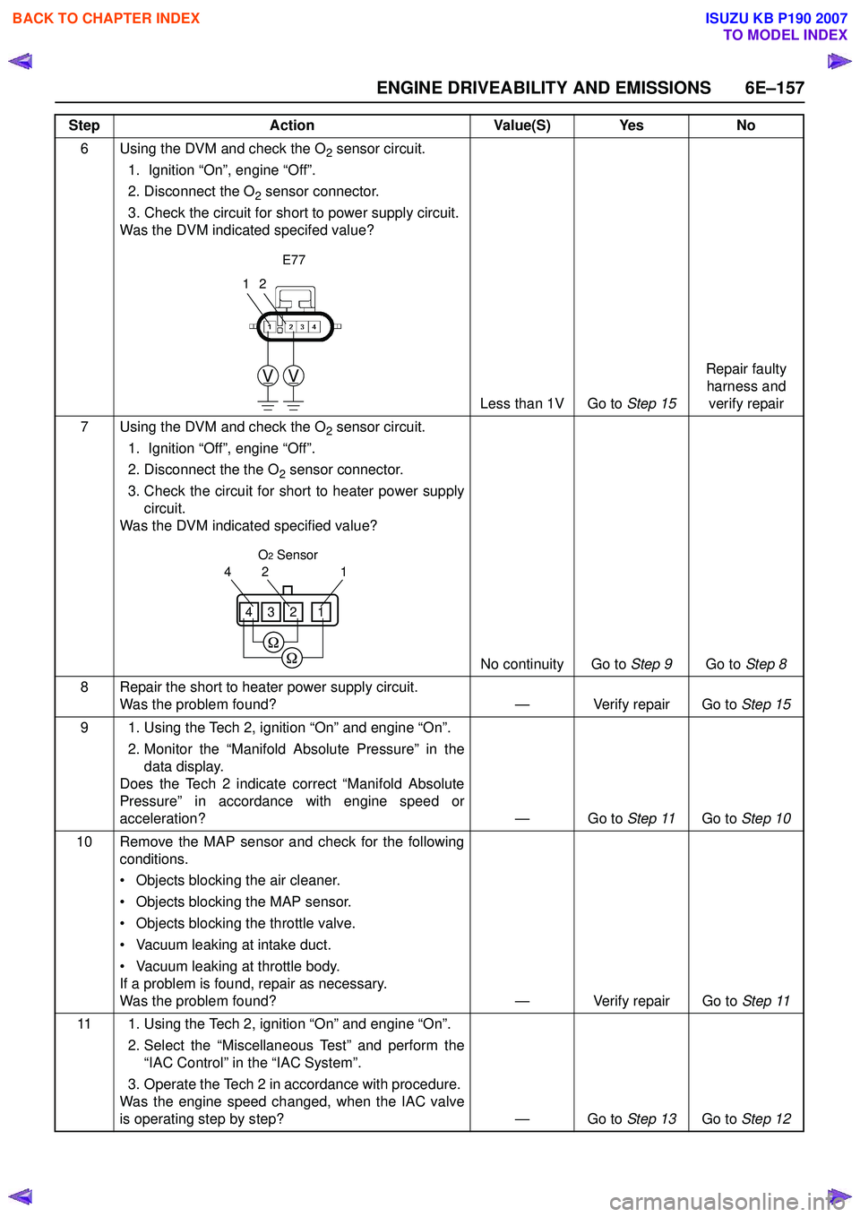
ENGINE DRIVEABILITY AND EMISSIONS 6E–157
6 Using the DVM and check the O2 sensor circuit.
1. Ignition “On”, engine “Off”.
2. Disconnect the O
2 sensor connector.
3. Check the circuit for short to power supply circuit.
Was the DVM indicated specifed value?
Less than 1V Go to Step 15Repair faulty
harness and verify repair
7 Using the DVM and check the O
2 sensor circuit.
1. Ignition “Off”, engine “Off”.
2. Disconnect the the O
2 sensor connector.
3. Check the circuit for short to heater power supply circuit.
Was the DVM indicated specified value?
No continuity Go to Step 9Go to Step 8
8 Repair the short to heater power supply circuit. Was the problem found? — Verify repair Go to Step 15
9 1. Using the Tech 2, ignition “On” and engine “On”. 2. Monitor the “Manifold Absolute Pressure” in thedata display.
Does the Tech 2 indicate correct “Manifold Absolute
Pressure” in accordance with engine speed or
acceleration? — Go to Step 11Go to Step 10
10 Remove the MAP sensor and check for the following conditions.
• Objects blocking the air cleaner.
• Objects blocking the MAP sensor.
• Objects blocking the throttle valve.
• Vacuum leaking at intake duct.
• Vacuum leaking at throttle body.
If a problem is found, repair as necessary.
Was the problem found? — Verify repair Go to Step 11
11 1. Using the Tech 2, ignition “On” and engine “On”. 2. Select the “Miscellaneous Test” and perform the“IAC Control” in the “IAC System”.
3. Operate the Tech 2 in accordance with procedure.
Was the engine speed changed, when the IAC valve
is operating step by step? — Go to Step 13Go to Step 12
Step
Action Value(S) Yes No
12
VV
E77
1
24
1234
O2 Sensor
BACK TO CHAPTER INDEX
TO MODEL INDEX
ISUZU KB P190 2007