2007 ISUZU KB P190 vacuum
[x] Cancel search: vacuumPage 2084 of 6020
6A-70 ENGINE MECHANICAL (C24SE)
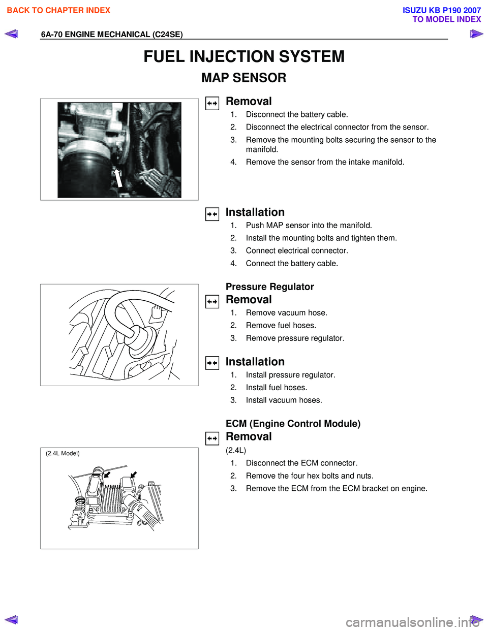
FUEL INJECTION SYSTEM
MAP SENSOR
Removal
1. Disconnect the battery cable.
2. Disconnect the electrical connector from the sensor.
3. Remove the mounting bolts securing the sensor to the manifold.
4. Remove the sensor from the intake manifold.
Installation
1. Push MAP sensor into the manifold.
2. Install the mounting bolts and tighten them.
3. Connect electrical connector.
4. Connect the battery cable.
Pressure Regulator
Removal
1. Remove vacuum hose.
2. Remove fuel hoses.
3. Remove pressure regulator.
Installation
1. Install pressure regulator.
2. Install fuel hoses.
3. Install vacuum hoses.
ECM (Engine Control Module)
Removal
(2.4L)
1. Disconnect the ECM connector.
2. Remove the four hex bolts and nuts.
3. Remove the ECM from the ECM bracket on engine.
BACK TO CHAPTER INDEX
TO MODEL INDEX
ISUZU KB P190 2007
Page 2116 of 6020
6B-12 ENGINE COOLING
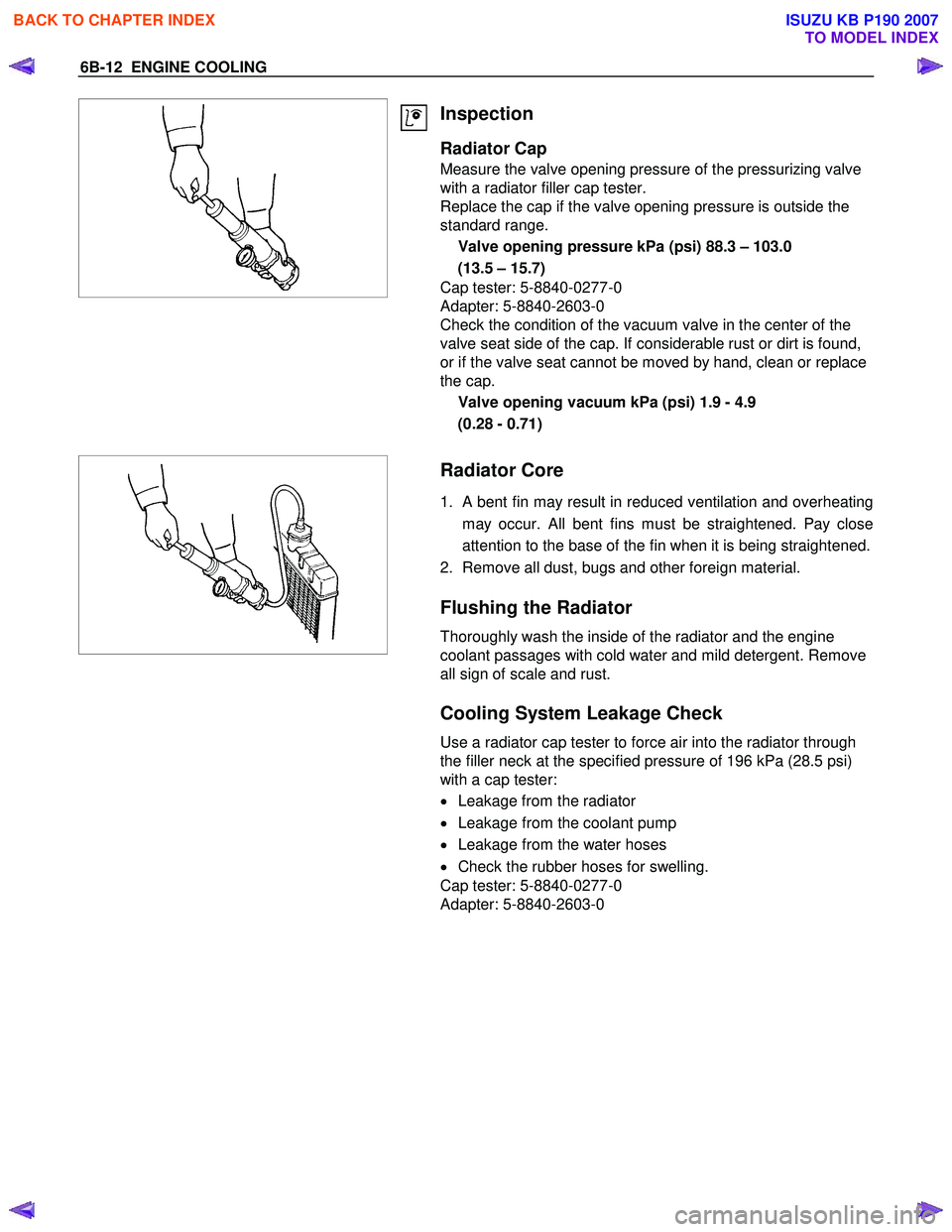
Inspection
Radiator Cap
Measure the valve opening pressure of the pressurizing valve
with a radiator filler cap tester.
Replace the cap if the valve opening pressure is outside the
standard range.
Valve opening pressure kPa (psi) 88.3 – 103.0
(13.5 – 15.7)
Cap tester: 5-8840-0277-0
Adapter: 5-8840-2603-0
Check the condition of the vacuum valve in the center of the
valve seat side of the cap. If considerable rust or dirt is found,
or if the valve seat cannot be moved by hand, clean or replace
the cap.
Valve opening vacuum kPa (psi) 1.9 - 4.9
(0.28 - 0.71)
Radiator Core
1. A bent fin may result in reduced ventilation and overheating
may occur. All bent fins must be straightened. Pay close
attention to the base of the fin when it is being straightened.
2. Remove all dust, bugs and other foreign material.
Flushing the Radiator
Thoroughly wash the inside of the radiator and the engine
coolant passages with cold water and mild detergent. Remove
all sign of scale and rust.
Cooling System Leakage Check
Use a radiator cap tester to force air into the radiator through
the filler neck at the specified pressure of 196 kPa (28.5 psi)
with a cap tester:
• Leakage from the radiator
• Leakage from the coolant pump
• Leakage from the water hoses
• Check the rubber hoses for swelling.
Cap tester: 5-8840-0277-0
Adapter: 5-8840-2603-0
BACK TO CHAPTER INDEX
TO MODEL INDEX
ISUZU KB P190 2007
Page 2134 of 6020
6C-16 ENGINE FUEL (C24SE)
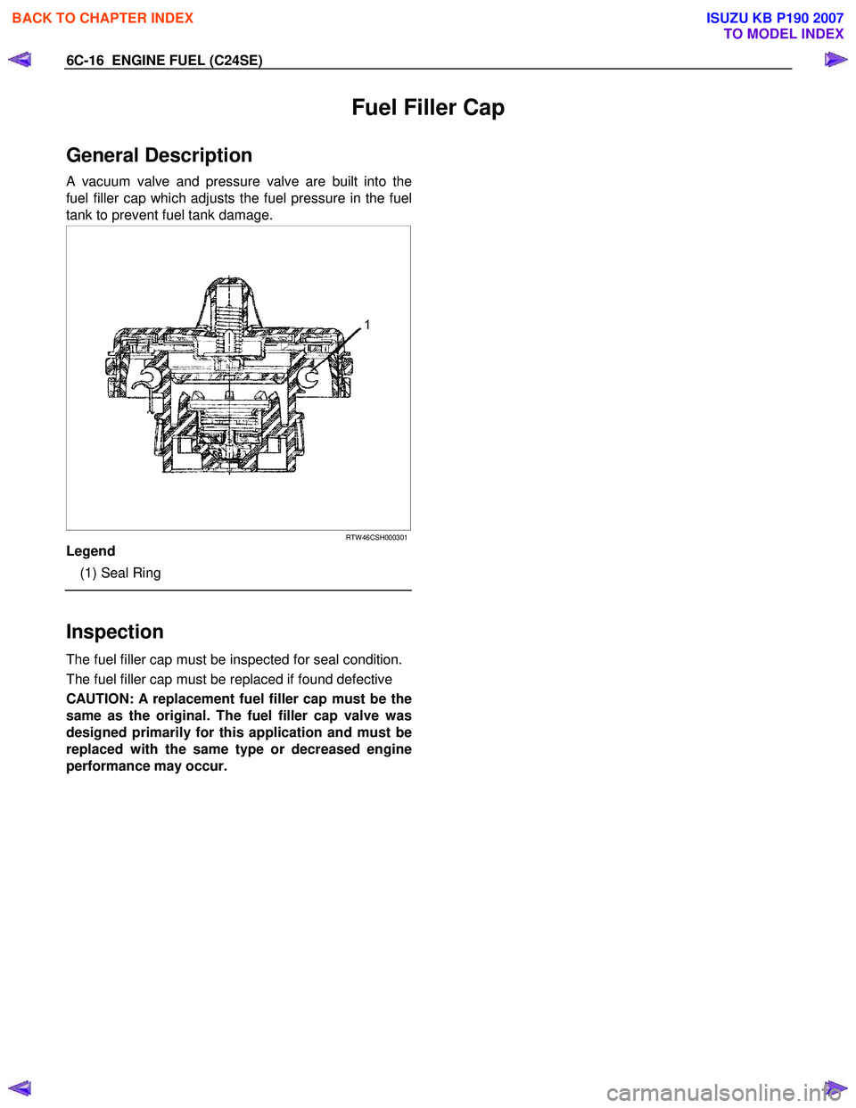
Fuel Filler Cap
General Description
A vacuum valve and pressure valve are built into the
fuel filler cap which adjusts the fuel pressure in the fuel
tank to prevent fuel tank damage.
RTW 46CSH000301
Legend
(1) Seal Ring
Inspection
The fuel filler cap must be inspected for seal condition.
The fuel filler cap must be replaced if found defective
CAUTION: A replacement fuel filler cap must be the
same as the original. The fuel filler cap valve was
designed primarily for this application and must be
replaced with the same type or decreased engine
performance may occur.
BACK TO CHAPTER INDEX
TO MODEL INDEX
ISUZU KB P190 2007
Page 2176 of 6020
6E–6 ENGINE DRIVEABILITY AND EMISSIONS
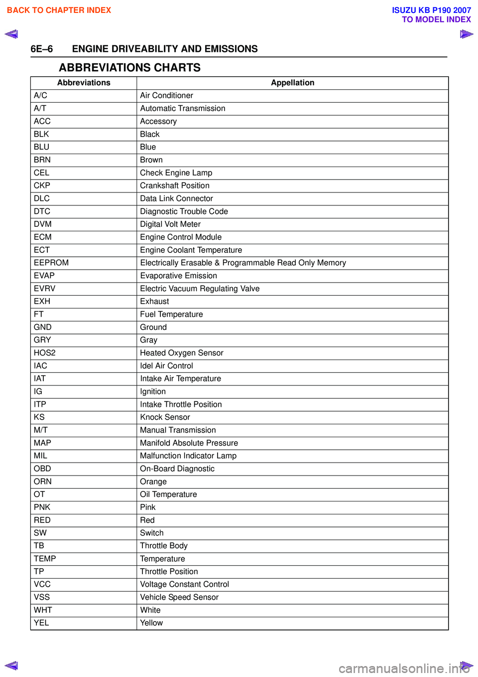
ABBREVIATIONS CHARTS
AbbreviationsAppellation
A/C Air Conditioner
A/T Automatic Transmission
ACC Accessory
BLK Black
BLU Blue
BRN Brown
CEL Check Engine Lamp
CKP Crankshaft Position
DLC Data Link Connector
DTC Diagnostic Trouble Code
DVM Digital Volt Meter
ECM Engine Control Module
ECT Engine Coolant Temperature
EEPROM Electrically Erasable & Programmable Read Only Memory
EVAP Evaporative Emission
EVRV Electric Vacuum Regulating Valve
EXH Exhaust
FT Fuel Temperature
GND Ground
GRY Gray
HOS2 Heated Oxygen Sensor
IAC Idel Air Control
IAT Intake Air Temperature
IG Ignition
ITP Intake Throttle Position
KS Knock Sensor
M/T Manual Transmission
MAP Manifold Absolute Pressure
MIL Malfunction Indicator Lamp
OBD On-Board Diagnostic
ORN Orange
OT Oil Temperature
PNK Pink
RED Red
SW Switch
TB Throttle Body
TEMP Temperature
TP Throttle Position
VCC Voltage Constant Control
VSS Vehicle Speed Sensor
WHT White
YEL Yellow
BACK TO CHAPTER INDEX
TO MODEL INDEX
ISUZU KB P190 2007
Page 2223 of 6020
ENGINE DRIVEABILITY AND EMISSIONS 6E–53
Fuel Metering System Components
The fuel metering system is made up of the following
parts.
• Fuel injector
• Throttle body
•Fuel rail
• Fuel pressure regulator
•ECM
• Crankshaft position (CKP) sensor
• Idle air control (IAC) valve
•Fuel pump
Fuel Injector
The group fuel injection fuel injector is a solenoid
operated device controlled by the ECM. The ECM
energizes the solenoid, which opens a valve to allow
fuel delivery.
The fuel is injected under pressure in a conical spray
pattern at the opening of the intake valve. Excess fuel
not used by the injectors passes through the fuel
pressure regulator before being returned to the fuel
tank.
Fuel Pressure Regulator
The fuel pressure regulator is a diaphragm-operated
relief valve mounted on the fuel rail with fuel pump
pressure on one side and manifold pressure on the
other side. The fuel pressure regulator maintains the
fuel pressure available to the injector at three times
barometric pressure adjusted for engine load. It may be
serviced separately.
If the pressure is too low or poor performance, DTC
P0131 or P1171 will be the result. If the pressure is too
high, DTC P0132 or P1167 will be the result. Refer to
Fuel System Diagnosis for information on diagnosing
fuel pressure conditions.
Fuel Rail
The fuel rail is mounted to the top of the engine and
distributes fuel to the individual injectors. Fuel is
delivered to the fuel inlet tube of the fuel rail by the fuel
lines. The fuel goes through the fuel rail to the fuel
pressure regulator. The fuel pressure regulator
maintains a constant fuel pressure at the injectors.
Remaining fuel is then returned to the fuel tank.
Fuel Pump Electrical Circuit
When the key is first turned ON, the ECM energizes the
fuel pump relay for two seconds to build up the fuel
pressure quickly. If the engine is not started within two
seconds, the ECM shuts the fuel pump off and waits
until the engine is cranked. When the engine is cranked
and the 58X crankshaft position signal has been
detected by the ECM, the ECM supplies 12 volts to the
fuel pump relay to energize the electric in-tank fuel
pump.
An inoperative fuel pump will cause a “no-start”
condition. A fuel pump which does not provide enough pressure will result in poor performance.
Thottle Body Unit
The throttle body has a throttle plate to control the
amount of air delivered to the engine. The Thottle
position sensor and IAC valve are also mounted on the
throttle body.
Vacuum ports located behind the throttle plate provide
the vacuum signals needed by various components.
Engine coolant is directed through a coolant cavity in
the throttle body to warm the throttle valve and to
prevent icing.
BACK TO CHAPTER INDEX
TO MODEL INDEX
ISUZU KB P190 2007
Page 2227 of 6020
ENGINE DRIVEABILITY AND EMISSIONS 6E–57
GENERAL DESCRIPTION FOR
EVAPORATIVE EMISSION SYSTEM
EVAP Emission Control System Purpose
The basic evaporative emission control system used on
the charcoal canister storage method. The method
transfers fuel vapor from the fuel tank to an activated
carbon (charcoal) storage devise to hold the vapors
when the vehicle is not operating.
The canister is located on the rear axle housing by the
frame cross-member.
When the engine is running, the fuel vapor is purged
from the carbon element by intake air flow and
consumed in the normal combustion process.
EVAP Emission Control System Operation
The EVAP canister purge is controlled by a solenoid
valve that allows the manifold vacuum to purge the
canister. The engine control module (ECM) supplies a
ground to energize the solenoid valve (purge on). The
EVAP purge solenoid control is pulse-width modulated
(PWM) (turned on and off several times a second). The
duty cycle (pulse width) is determined by engine
operating conditions including load, throttle position,
coolant temperature and ambient temperature. The duty
cycle is calculated by the ECM. the output is
commanded when the appropriate conditions have
been met. These conditions are:
• The engine is fully warmed up.
• The engine has been running for a specified time.
• The IAT reading is above 10°C (50°F).
• Purge/Vacuum Hoses. Made of rubber compounds, these hoses route the gasoline fumes from their
sources to the canister and from the canister to the
intake air flow.
• EVAP Canister. Mounted on a bracket ahead of the fuel tank, the canister stores fuel vapors until the
ECM determined that engine conditions are right for
them to be removed and burned.
Poor idle, stalling and Poor driveability can be caused
by:
• A malfunctioning purge solenoid.
• A damaged canister.
• Hoses that are split, cracked, or not connected properly.
System Fault Detection
The EVAP leak detection strategy is based on applying
vacuum to the EVAP system and monitoring vacuum
decay. At an appropriate time, the EVAP purge solenoid
is turned “ON,” allowing the engine vacuum to draw a
small vacuum on the entire evaporative emission
system.
After the desired vacuum level has been achieved, the
EVAP purge solenoid is turned “OFF,” sealing the
system. A leak is detected by monitoring for a decrease
in vacuum level over a given time period, all other
variables remaining constant.
If the desired vacuum level cannot be achieved in the
test described above, a large leak or a faulty EVAP
purge control solenoid valve is indicated.
Leaks can be caused by the following conditions:
• Missing or faulty fuel cap
• Disconnected, damaged, pinched, or blocked EVAP purge line
• Disconnected, damaged, pinched, or blocked fuel tank vapor line
• Disconnected or faulty EVAP purge control solenoid valve
• Open ignition feed circuit to the purge solenoid
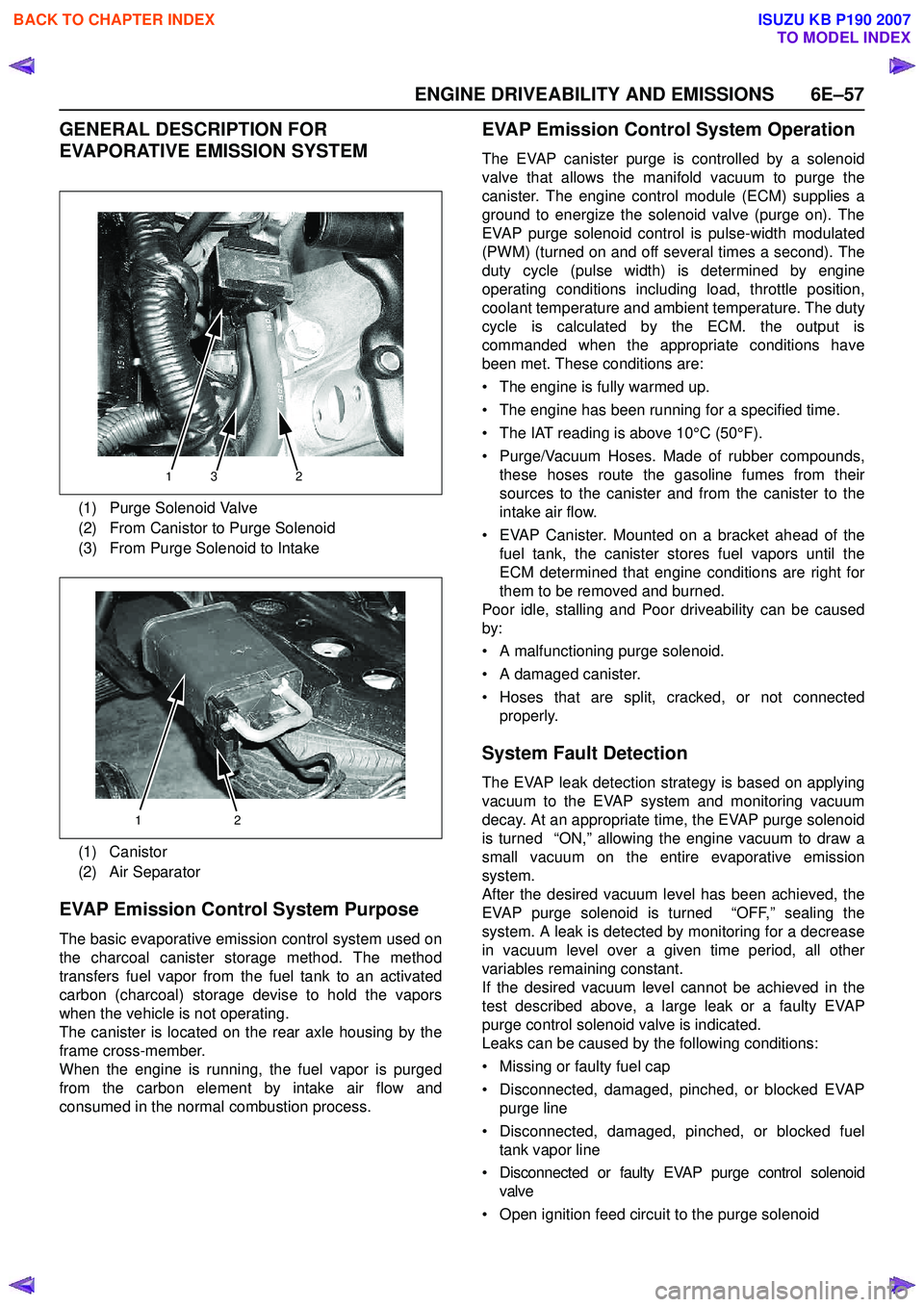
(1) Purge Solenoid Valve
(2) From Canistor to Purge Solenoid
(3) From Purge Solenoid to Intake
(1) Canistor
(2) Air Separator
132
12
BACK TO CHAPTER INDEX
TO MODEL INDEX
ISUZU KB P190 2007
Page 2228 of 6020
6E–58 ENGINE DRIVEABILITY AND EMISSIONS
• Damaged EVAP canister
• Leaking fuel sender assembly O-ring
• Leaking fuel tank or fuel filler neck
The ECM supplies a ground to energize the purge
control solenoid valve (purge “ON” ). The EVAP purge
control is turned “ON” and “OFF,” several times a
second. The duty cycle (pulse width) is determined by
engine operating conditions including load, throttle
position, coolant temperature and ambient temperature.
The duty cycle is calculated by the ECM and the output
is commanded when the appropriate conditions have
been met.
The system checks for conditions that cause the EVAP
system to purge continuously by commanding the EVAP
purge solenoid “OFF”, EVAP purge solenoid duty ratio
“0%”. If fuel tank vacuum level increases during the test,
a continuous purge flow condition is indicated. This can
be caused by the following conditions:
• EVAP purge solenoid leaking
• EVAP purge and engine vacuum lines switched at the EVAP purge control solenoid valve
• EVAP purge control solenoid valve driver circuit grounded
BACK TO CHAPTER INDEX
TO MODEL INDEX
ISUZU KB P190 2007
Page 2233 of 6020
ENGINE DRIVEABILITY AND EMISSIONS 6E–63
3. Check Bulletins and Troubleshooting Hints
NOTE: As estimated 30 percent of successful vehicle
repairs are diagnosed with this step!
What you should do
You should have enough information gained from
preliminary checks to accurately search for a bulletin
and other related service information. Some service
manual sections provide troubleshooting hints that
match symptoms with specific complaints.
What resources you should use
You should use the following resources for assistance in
checking for bulletins and troubleshooting hints:
• Printed bulletins
• Access ISUZU Bulletin Web site.
• Videotapes
• Service manual
4. Perform Service Manual Diagnostic Checks
What you should do
The “System Checks” in most service manual sections
and in most cells of section 8A (electrical) provide you
with:
• A systematic approach to narrowing down the possible causes of a system fault
• Direction to specific diagnostic procedures in the service manual
• Assistance to identify what systems work correctly
What resources you should use
Whenever possible, you should use the following
resources to perform service manual checks:
• Service manual
• Technical equipment (for viewing DTCs and analyzing data)
• Digital multimeter and circuit testing tools
• Other tools as needed
5a and 5b. Perform Service Manual Diagnostic Procedures
NOTE: An estimated 40 percent of successful vehicle
repairs are diagnosed with these steps!
What you should do
When directed by service manual diagnostic checks,
you must then carefully and accurately perform the
steps of diagnostic procedures to locate the fault related to the customer complaint.
What resources you should use
Whenever appropriate, you should use the following
resources to perform service manual diagnostic
procedures:
• Service manual
• Technical equipment (for analyzing diagnostic data)
• Digital multimeter and circuit testing tools
• Essential and special tools
5c. Technician Self Diagnoses
When there is no DTC stored and no matching
symptom for the condition identified in the service
manual, you must begin with a thorough understanding
of how the system(s) operates. Efficient use of the
service manual combined with you experience and a
good process of elimination will result in accurate
diagnosis of the condition.
What you should do
Step 1: Identify and understand the suspect
circuit(s)
Having completed steps 1 through 4 of the Strategy
Based Diagnostics chart, you should have enough
information to identify the system(s) or sub-system(s)
involved. Using the service manual, you should
determine and investigate the following circuit
characteristics:
• Electrical: – How is the circuit powered (power distributioncharts and/or fuse block details)?
– How is the circuit grounded (ground distribution charts)?
– How is the circuit controlled or sensed (theory of operation):
– If it is a switched circuit, is it normally open or normally closed?
– Is the power switched or is the ground switched?
– Is it a variable resistance circuit (ECT sensor or TP sensor, for example)?
– Is it a signal generating device (MAF sensor of VSS, for example)?
– Does it rely on some mechanical/vacuum device to operate?
•Physical:
– Where are the circuit components (componentlocators and wire harness routing diagrams):
– Are there areas where wires could be chafed or pinched (brackets or frames)?
– Are there areas subjected to extreme temperatures?
BACK TO CHAPTER INDEX
TO MODEL INDEX
ISUZU KB P190 2007