2007 ISUZU KB P190 vacuum
[x] Cancel search: vacuumPage 1668 of 6020
ENGINE CONTROL SYSTEM (4JK1/4JJ1) 6E-51
Turbocharger Solenoid Command
This parameter displays the turbocharger nozzle
control solenoid valve control duty ratio based on inputs
to the ECM from various engine sensors. The scan
tool will display a lower percentage when the nozzle is
controlled to open (vacuum pressure supply to the
actuator is reduced). The scan tool will display a higher
percentage when the nozzle is controlled to close
(vacuum pressure supply to the actuator is increased).
Desired Boost Pressure
This parameter displays boost pressure desired by the
ECM based on current driving conditions. This can be
compared to the actual boost pressure to determine
sensor accuracy or turbocharger control problems.
Boost Pressure
This parameter displays the boost pressure in the
intake duct as calculated by the ECM using the signal
from the boost pressure sensor. The scan tool will
display a low boost pressure when the low engine load,
and a high boost pressure when the high engine load.
Note that the true boost pressure is determined by
subtracting barometric pressure from the actual
reading.
Boost Pressure Sensor
This parameter displays the voltage signal sent to the
ECM from the boost pressure sensor. Boost pressure
sensor is a range of value indicating a low voltage
when the boost pressure is low (idle or lower engine
load) and a high voltage when the boost pressure is
high (higher engine load).
Desired Fuel Rail Pressure
This parameter displays fuel rail pressure desired by
the ECM based on current driving conditions. This can
be compared to the actual fuel rail pressure to
determine sensor accuracy or fuel pressure control
problems.
Fuel Rail Pressure
This parameter displays the fuel rail pressure as
calculated by the ECM using the signal from the fuel
rail pressure (FRP) sensor. The scan tool will display a
low pressure when the low engine load, and a high
pressure when the high engine load.
Fuel Rail Pressure Sensor
This parameter displays the voltage signal sent to the
ECM from the fuel rail pressure (FRP) sensor. FRP
sensor is a range of value indicating a low voltage
when the fuel rail pressure is low, and a high voltage
when the fuel rail pressure is high.
FRP Commanded Fuel Flow (Fuel Rail Pressure)
This parameter displays the commanded fuel flow
quantity of the fuel rail pressure (FRP) regulator to the
fuel rail. FRP Regulator Command (Fuel Rail Pressure)
This parameter displays the fuel rail pressure (FRP)
regulator control duty ratio based on inputs to the ECM
from various engine sensors. The scan tool will display
a lower percentage when the FRP regulator is
controlled to open (fuel supply quantity to the fuel rail is
increased). The scan tool will display higher
percentage when the FRP regulator is controlled to
close (fuel supply quantity to the fuel rail is reduced).
FRP Regulator Feedback (Fuel Rail Pressure)
This parameter displays the fuel rail pressure (FRP)
regulator control feedback current as measured by the
ECM. The scan tool will display a low current when the
FRP regulator is controlled to open (fuel supply
quantity to the fuel rail is increased). The scan tool will
display a high current when the FRP regulator is
controlled to close (fuel supply quantity to the fuel rail is
reduced).
Accelerator Pedal Position
This parameter displays the angle of the accelerator
pedal as calculated by the ECM using the signals from
the accelerator pedal position (APP) sensors. The scan
tool will display linearly from 0 to 100% according to the
pedal operation.
APP Sensor 1 (Accelerator Pedal Position)
This parameter displays the voltage signal sent to the
ECM from the accelerator pedal position (APP) sensor
1 of the APP sensor assembly. APP sensor 1 is a
range of value indicating a low voltage when the
accelerator pedal is not depressed, and a high voltage
when the accelerator pedal is fully depressed.
APP Sensor 2 (Accelerator Pedal Position)
This parameter displays the voltage signal sent to the
ECM from the accelerator pedal position (APP) sensor
2 of the APP sensor assembly. APP sensor 2 is a
range of value indicating a high voltage when the
accelerator pedal is not depressed, and a low voltage
when the accelerator pedal is fully depressed.
APP Sensor 3 (Accelerator Pedal Position)
This parameter displays the voltage signal sent to the
ECM from the accelerator pedal position (APP) sensor
3 of the APP sensor assembly. APP sensor 3 is a
range of value indicating a high voltage when the
accelerator pedal is not depressed, and a middle
voltage when the accelerator pedal is fully depressed.
EGR Solenoid Command
This parameter displays the EGR solenoid valve
control duty ratio based on inputs to the ECM from
various engine sensors. The scan tool will display a
lower percentage when the EGR solenoid valve is
controlled to close (EGR gas supply to the intake is
reduced). The scan tool will display a higher
percentage when the EGR solenoid valve is controlled
to open (EGR gas supply to the intake is increased).
BACK TO CHAPTER INDEX
TO MODEL INDEX
ISUZU KB P190 2007
Page 1670 of 6020
ENGINE CONTROL SYSTEM (4JK1/4JJ1) 6E-53
Cam/ Crank Sensor Signal/ Synchronization Status
This parameter displays the synchronization state of
the crankshaft position (CKP) sensor signal and
camshaft position (CMP) sensor signal. Asynchronous
indicates the CMP sensor signal is not detected or only
CKP sensor signal is detected. No Crank Signal
indicates CMP sensor signal is detected but CKP
sensor signal is not detected. Synchronous indicates
both sensor signals are detected correctly.
Engine Runtime
This parameter displays the time elapsed since the
engine start. The scan tool will display the time in
hours, minutes and seconds. The engine run time will
reset to zero as soon as the ignition switch is OFF.
Vehicle Speed
This parameter indicates the vehicle speed calculated
by the ECM using the signal from the vehicle speed
sensor (VSS). The scan tool will display a low value at
lower vehicle speeds, and a high value at higher
vehicle speeds.
Transmission Gear
This parameter displays the estimated transmission
gear position as calculated by the ECM based on
inputs from the vehicle speed and the engine speed.
Starter Switch
This parameter displays the input status of the starter
switch to the ECM. When the ignition switch is turned at
START position, the scan tool displays On.
Ignition Switch
This parameter displays the input status of the ignition
switch to the ECM. When the ignition switch is turned
ON position, the scan tool displays On.
Ignition Voltage
This parameter displays the ignition voltage measured
at the ignition feed circuit of the ECM. Voltage is
applied to the ECM when the ignition switch is ON
position.
Battery Voltage
This parameter displays the battery voltage measured
at the ECM main relay switched voltage feed circuit of
the ECM. Voltage is applied to the ECM when the ECM
main relay is energized.
Fuel Pump Relay Command
This parameter displays the commanded state of the
fuel pump relay control circuit. On indicates the fuel
pump relay control circuit is being grounded by the
ECM, allowing fuel pumping from the tank.
Swirl Control Solenoid Command
This parameter displays the commanded state of the
swirl control solenoid control circuit. On indicates the
swirl control solenoid control circuit is being grounded
by the ECM, allowing vacuum pressure to the swirl
control
actuator. Fuel Filter Switch
This parameter displays the input state of the fuel
pressure switch to the ECM. When the large vacuum
pressure is generated in the fuel suction line such as
clogged fuel filter, the scan tool displays Off.
A/C Request Signal
This parameter displays the input state of the air
conditioning (A/C) request to the ECM from the
heating, ventilation, and air conditioning (HVAC)
controls. When the HVAC system is requesting to
ground the A/C compressor clutch, the scan tool
displays On.
A/C Relay Command
This parameter displays the commanded state of the A/
C compressor relay control circuit. On indicates the A/C
compressor relay control circuit is being grounded by
the ECM, allowing voltage to the A/C compressor.
Park/ Neutral Switch
This parameter displays the input state of the neutral
switch to the ECM. When the transmission gear is Park
or Neutral, the scan tool displays Neutral.
Glow Relay Command
This parameter displays the commanded state of the
glow relay control circuit. On indicates the glow relay
control circuit is being grounded by the ECM, allowing
voltage to the glow plugs.
Glow Plug Lamp Command
This parameter displays the commanded state of the
glow indicator lamp control circuit. The glow indicator
lamp should be On when the scan tool indicates
command On. The glow indicator lamp should be Off
when the scan tool indicates command Off.
Brake Switch 1
This parameter displays the input state of the brake
pedal switch 1 to the ECM. When the brake pedal is
depressed, scan tool displays Applied.
Brake Switch 2
This parameter displays the input state of the brake
pedal switch 2 to the ECM. When the brake pedal is
depressed, scan tool displays Applied.
Clutch Pedal Switch
This parameter displays the input state of the clutch
pedal switch to the ECM. When the clutch pedal is
depressed, scan tool displays Applied.
Cruise Main Lamp Command
This parameter displays the commanded state of the
cruise main lamp control circuit. The cruise main lamp
should be On when the scan tool indicates command
On. The cruise main lamp should be Off when the scan
tool indicates command Off.
Cruise Main Switch
This parameter displays the input state of the cruise
main switch to the ECM. When the Cruise Main switch
is pushed, the scan tool displays On.
BACK TO CHAPTER INDEX
TO MODEL INDEX
ISUZU KB P190 2007
Page 1672 of 6020

ENGINE CONTROL SYSTEM (4JK1/4JJ1) 6E-55
Scan Tool Output Controls
Scan Tool Output ControlDescriptions
Fuel Supply Pump Learn Resetting The purpose of this test to reset the fuel supply pump adjustment value.
Important: The fuel supply pump relearn procedure must be done when the fuel supply
pump or engine is replaced, or an ECM from another vehicle is installed. Refer to Fuel
Supply Pump Replacement.
Fuel Pressure Control The purpose of this test is for checking whether the fuel rail pressure is changing when
commanded within 30 to 80MPa (4,350 to 11,600psi) when commanded. Faulty fuel supply
pump, fuel rail pressure (FRP) regulator, pressure limiter valve or other fuel lines could be
considered if the differential fuel rail pressure is large.
Pilot Injection Control The purpose of this test is for checking whether the pilot fuel injection is operated when it is
commanded to ON/ OFF. Faulty injector(s) could be considered if engine noise does not
change when commanded OFF.
Injection Timing Control The purpose of this test is for checking whether the main injection timing is changing when
commanded Retard/ Advance within -5 to 5 °CA.
Injector Force Drive The purpose of this test is for checking whether the fuel injector is correctly operating when
commanded ON. Faulty injector(s) could be considered if it does not create a clicking noise
(solenoid operating noise), contains an interrupted noise or has abnormal noise when
commanded ON.
Cylinder Balance Test The purpose of this test is for checking whether the fuel injector is operating when
commanded ON/ OFF. Faulty injector(s) could be considered if engine does not change
speed when commanded OFF.
Intake Throttle Solenoid Control The purpose of this test is for checking whether the intake throttle valve is correctly moved
with command. Restricted valve movement by foreign materials, excessive deposits or a
faulty valve could be considered if the position difference is large.
EGR Solenoid Control The purpose of this test is for checking whether the EGR valve is correctly moved with
command. Restricted valve movement by foreign materials, excessive deposits or a faulty
valve could be considered if the position difference is large.
Swirl Control Solenoid Control The purpose of this test is for checking whether the swirl control solenoid is operating when
commanded ON. Faulty circuit(s) or a faulty solenoid could be considered if not energizing
when commanded ON.
Turbocharger Solenoid Control The purpose of this test is for checking whether the turbocharger nozzle control actuator is
correctly moved with command. Restricted actuator movement by foreign materials,
excessive deposits, misrouted vacuum hoses, a faulty solenoid or a faulty actuator could be
considered if the actuator is not moved correctly.
Glow Relay Control The purpose of this test is for checking whether the glow relay is operating when
commanded ON. Faulty circuit(s) or a faulty glow relay could be considered if not energizing
when commanded ON.
Glow Plug Lamp Control The purpose of this test is for checking whether the glow indicator lamp is operating when
commanded ON. Faulty circuit(s) or an open circuit could be considered when not operating
when commanded ON.
Malfunction Indicator Lamp (MIL) Control The purpose of this test is for checking whether the MIL is operating when commanded ON.
Faulty circuit(s) or an open circuit could be considered when not operating when
commanded ON.
Service Vehicle Soon (SVS) Lamp Control The purpose of this test is for checking whether the SVS lamp is operating when
commanded ON. Faulty circuit(s) or an open circuit could be considered when not operating
when commanded ON.
Cruise Main Lamp Control The purpose of this test is for checking whether the cruise main lamp is operating when
commanded ON. Faulty circuit(s) or an open circuit could be considered when not operating
when commanded ON.
Cruise Set Lamp Control The purpose of this test is for checking whether the cruise set lamp is operating when
commanded ON. Faulty circuit(s) or an open circuit could be considered when not operating
when commanded ON.
BACK TO CHAPTER INDEX
TO MODEL INDEX
ISUZU KB P190 2007
Page 1688 of 6020
ENGINE CONTROL SYSTEM (4JK1/4JJ1) 6E-71
DTC P0045 (Flash Code 33)
Circuit Description
The position of the turbocharger nozzle is controlled by
the ECM. The ECM utilizes a turbocharger nozzle
control solenoid valve and a boost pressure sensor to
control the turbocharger nozzles. When the engine is
not under load, the turbocharger nozzles are in an open
position, or no boost condition. When the engine is
under load, the ECM commands the control solenoid
valve to close the turbocharger nozzles, thus
increasing the boost. The ECM will vary the boost
dependant upon the load requirements of the engine.
The ECM uses a pulse width modulation (PWM) on the
control circuit to open and control the solenoid valve. If
the ECM detects an open circuit or short circuit on the
solenoid valve circuit, this DTC will set.
Condition for Running the DTC • The ignition switch is ON.
Condition for Setting the DTC
Either of following condition is met: • The ECM detects a low voltage condition on the turbocharger nozzle control solenoid circuit when
the solenoid is commanded OFF.
• The ECM detects a high voltage condition on the turbocharger nozzle control solenoid circuit when
the solenoid is commanded ON. Action Taken When the DTC Sets
• The ECM illuminates the MIL when the diagnostic runs and fails. Refer to DTC Type Definitions for
Action Taken When the DTC Sets - Type A.
• The ECM limits fuel injection quantity.
• The ECM inhibits pilot injection.
• The ECM inhibits cruise control.
Condition for Clearing the DTC • Refer to DTC Type Definitions for Condition for Clearing the MIL/ DTC - Type A.
Diagnostic Aids • If an intermittent condition is suspected, refer to Intermittent Conditions in this section.
Test description
The number below refers to the step number on the
Circuit/ System Testing.
4. If the solenoid control circuit between the ECM and
the solenoid is normal, the test lamp changes from
Bright to Dim when commanded from Increase to
Decrease.
Schematic Reference: Vacuum Hose Routing
Diagram and Engine Controls Schematics
Connector End View Reference: Engine Controls
Connector End Views or ECM Connector End Views
Circuit/ System Testing DTC P0045
Step Action Value(s)Yes No
1 Did you perform the Diagnostic System Check -
Engine Controls? —
Go to Step 2 Go to Diagnostic
System Check -
Engine Controls
2 1. Install a scan tool.
2. Turn OFF the ignition for 30 seconds.
3. Start the engine.
4. Monitor the DTC Information with a scan tool.
Does the DTC fail this ignition? —
Go to Step 3 Go to Diagnostic
Aids
3 1. Turn OFF the ignition.
2. Disconnect the turbocharger nozzle control solenoid valve harness connector.
3. Connect a test lamp between the ignition voltage feed circuit (pin 2 of E-106) and a
known good ground.
4. Turn ON the ignition, with the engine OFF.
Does the test lamp illuminate? —
Go to Step 4 Go to Step 5
BACK TO CHAPTER INDEX
TO MODEL INDEX
ISUZU KB P190 2007
Page 1759 of 6020
6E-142 ENGINE CONTROL SYSTEM (4JK1/4JJ1)
DTC P0234 (Flash Code 42)
Circuit Description
The boost pressure sensor is located in the air
induction tubing. The sensor is a transducer that varies
voltage according to changes in the air pressure inside
the air tubing. The ECM monitors the boost pressure
sensor signal for abnormal values. If the ECM detects
that the sensor signal is excessively high, this DTC will
set. This indicates excessive high boost pressure.
Condition for Running the DTC • DTCs P0045, P0107 and P0108 are not set.
• The ignition switch is ON.
• The engine is running.
Condition for Setting the DTC • The ECM detects that the actual boost pressure is more than 20 kPa (3 psi) over the desired boost
pressure under certain conditions for longer than
10 seconds.
Action Taken When the DTC Sets • The ECM illuminates the MIL when the diagnostic runs and fails. Refer to DTC Type Definitions for
Action Taken When the DTC Sets - Type A.
• The ECM limits fuel injection quantity.
• The ECM inhibits pilot injection.
Condition for Clearing the DTC • Refer to DTC Type Definitions for Condition for Clearing the MIL/ DTC - Type A.
• The ECM limits fuel injection quantity.
• The ECM inhibits pilot injection. • The ECM inhibits cruise control.
Diagnostic Aids • An open circuit or high resistance in the boost pressure low reference circuit may set this DTC.
• Misrouted vacuum hoses may set this DTC.
• Check the turbocharger nozzle control actuator for a sticking. Refer to Turbocharger in the Engine
Mechanical section.
• Use a scan tool to verify the integrity of the boost pressure sensor signal. Compare the Boost
Pressure to the Desired Boost Pressure under all
load conditions for an excessively high value.
• The fuel with which gasoline was mixed may set this DTC.
Test Description
The numbers below refer to the step number on the
Circuit/ System Testing.
3. A skewed boost pressure sensor value (shifted to a
higher pressure) can set this DTC. The Boost Pressure
on the scan tool should read near Barometric Pressure
(BARO) with the key ON and engine OFF.
4. A skewed BARO sensor value (shifted to a lower
pressure) may indicate a wrong boost pressure. The
BARO on the scan tool should read near surrounding
barometric pressure.
Schematic Reference: Vacuum Hose Routing
Diagram and Engine Controls Schematics
Connector End View Reference: Engine Controls
Connector End Views or ECM Connector End Views
Circuit/ System Testing DTC P0234
Step Action Value(s)Yes No
1 Did you perform the Diagnostic System Check -
Engine Controls? —
Go to Step 2 Go to Diagnostic
System - Check
Engine Controls
2 1. Install a scan tool.
2. Turn OFF the ignition for 30 seconds.
3. Start the engine.
4. Monitor the DTC Information with a scan tool.
Is DTC P0045, P0107, P0108, P0638, P1196,
P1197, P1198, P2227, P2228 or P2229 also set? —
Go to Applicable DTC Go to Step 3
3 1. Turn ON the ignition, with the engine OFF.
2. Observe the Boost Pressure and Barometric Pressure (BARO) with a scan tool.
Does the scan tool indicate that the difference
between the Boost Pressure and BARO is more
than the specified value? 10 kPa (1.5
psi)
Go to Step 4 Go to Step 5
BACK TO CHAPTER INDEX
TO MODEL INDEX
ISUZU KB P190 2007
Page 1760 of 6020
ENGINE CONTROL SYSTEM (4JK1/4JJ1) 6E-143
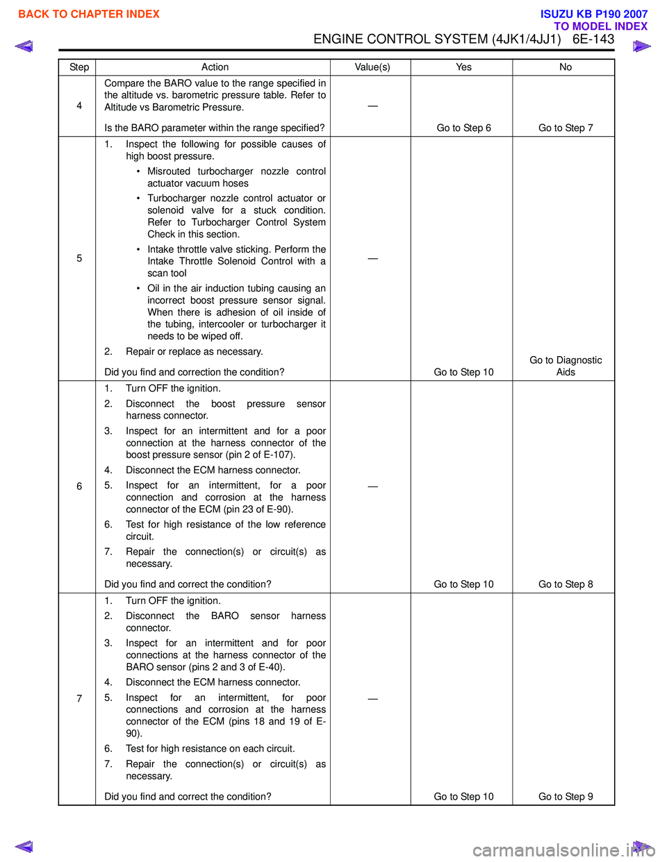
4Compare the BARO value to the range specified in
the altitude vs. barometric pressure table. Refer to
Altitude vs Barometric Pressure.
Is the BARO parameter within the range specified? —
Go to Step 6 Go to Step 7
5 1. Inspect the following for possible causes of
high boost pressure.
• Misrouted turbocharger nozzle control actuator vacuum hoses
• Turbocharger nozzle control actuator or solenoid valve for a stuck condition.
Refer to Turbocharger Control System
Check in this section.
• Intake throttle valve sticking. Perform the Intake Throttle Solenoid Control with a
scan tool
• Oil in the air induction tubing causing an incorrect boost pressure sensor signal.
When there is adhesion of oil inside of
the tubing, intercooler or turbocharger it
needs to be wiped off.
2. Repair or replace as necessary.
Did you find and correction the condition? —
Go to Step 10 Go to Diagnostic
Aids
6 1. Turn OFF the ignition.
2. Disconnect the boost pressure sensor harness connector.
3. Inspect for an intermittent and for a poor connection at the harness connector of the
boost pressure sensor (pin 2 of E-107).
4. Disconnect the ECM harness connector.
5. Inspect for an intermittent, for a poor connection and corrosion at the harness
connector of the ECM (pin 23 of E-90).
6. Test for high resistance of the low reference circuit.
7. Repair the connection(s) or circuit(s) as necessary.
Did you find and correct the condition? —
Go to Step 10 Go to Step 8
7 1. Turn OFF the ignition.
2. Disconnect the BARO sensor harness connector.
3. Inspect for an intermittent and for poor connections at the harness connector of the
BARO sensor (pins 2 and 3 of E-40).
4. Disconnect the ECM harness connector.
5. Inspect for an intermittent, for poor connections and corrosion at the harness
connector of the ECM (pins 18 and 19 of E-
90).
6. Test for high resistance on each circuit.
7. Repair the connection(s) or circuit(s) as necessary.
Did you find and correct the condition? —
Go to Step 10 Go to Step 9
Step
Action Value(s)Yes No
BACK TO CHAPTER INDEX
TO MODEL INDEX
ISUZU KB P190 2007
Page 1762 of 6020
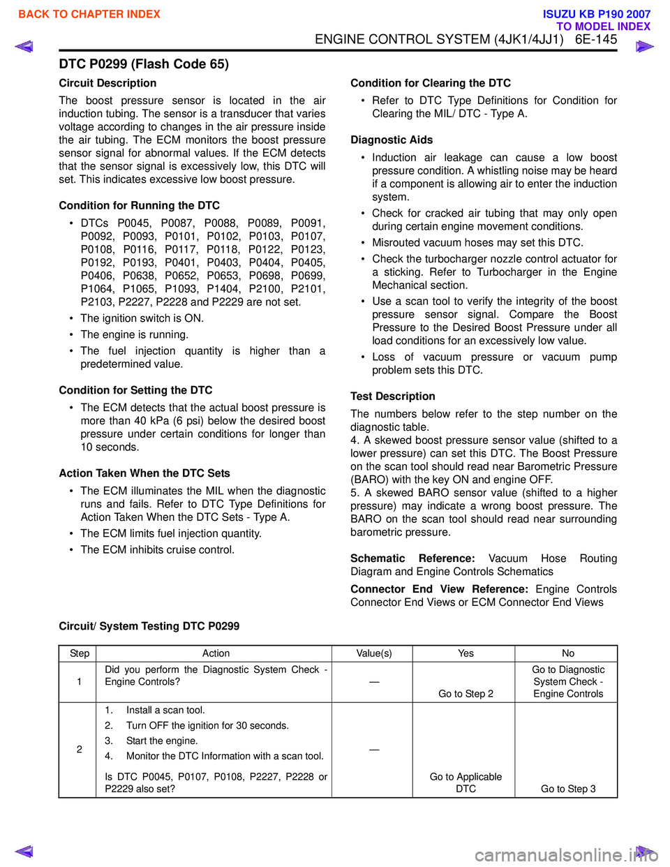
ENGINE CONTROL SYSTEM (4JK1/4JJ1) 6E-145
DTC P0299 (Flash Code 65)
Circuit Description
The boost pressure sensor is located in the air
induction tubing. The sensor is a transducer that varies
voltage according to changes in the air pressure inside
the air tubing. The ECM monitors the boost pressure
sensor signal for abnormal values. If the ECM detects
that the sensor signal is excessively low, this DTC will
set. This indicates excessive low boost pressure.
Condition for Running the DTC • DTCs P0045, P0087, P0088, P0089, P0091, P0092, P0093, P0101, P0102, P0103, P0107,
P0108, P0116, P0117, P0118, P0122, P0123,
P0192, P0193, P0401, P0403, P0404, P0405,
P0406, P0638, P0652, P0653, P0698, P0699,
P1064, P1065, P1093, P1404, P2100, P2101,
P2103, P2227, P2228 and P2229 are not set.
• The ignition switch is ON.
• The engine is running.
• The fuel injection quantity is higher than a predetermined value.
Condition for Setting the DTC • The ECM detects that the actual boost pressure is more than 40 kPa (6 psi) below the desired boost
pressure under certain conditions for longer than
10 seconds.
Action Taken When the DTC Sets • The ECM illuminates the MIL when the diagnostic runs and fails. Refer to DTC Type Definitions for
Action Taken When the DTC Sets - Type A.
• The ECM limits fuel injection quantity.
• The ECM inhibits cruise control. Condition for Clearing the DTC
• Refer to DTC Type Definitions for Condition for Clearing the MIL/ DTC - Type A.
Diagnostic Aids • Induction air leakage can cause a low boost pressure condition. A whistling noise may be heard
if a component is allowing air to enter the induction
system.
• Check for cracked air tubing that may only open during certain engine movement conditions.
• Misrouted vacuum hoses may set this DTC.
• Check the turbocharger nozzle control actuator for a sticking. Refer to Turbocharger in the Engine
Mechanical section.
• Use a scan tool to verify the integrity of the boost pressure sensor signal. Compare the Boost
Pressure to the Desired Boost Pressure under all
load conditions for an excessively low value.
• Loss of vacuum pressure or vacuum pump problem sets this DTC.
Test Description
The numbers below refer to the step number on the
diagnostic table.
4. A skewed boost pressure sensor value (shifted to a
lower pressure) can set this DTC. The Boost Pressure
on the scan tool should read near Barometric Pressure
(BARO) with the key ON and engine OFF.
5. A skewed BARO sensor value (shifted to a higher
pressure) may indicate a wrong boost pressure. The
BARO on the scan tool should read near surrounding
barometric pressure.
Schematic Reference: Vacuum Hose Routing
Diagram and Engine Controls Schematics
Connector End View Reference: Engine Controls
Connector End Views or ECM Connector End Views
Circuit/ System Testing DTC P0299
Step Action Value(s)Yes No
1 Did you perform the Diagnostic System Check -
Engine Controls? —
Go to Step 2 Go to Diagnostic
System Check -
Engine Controls
2 1. Install a scan tool.
2. Turn OFF the ignition for 30 seconds.
3. Start the engine.
4. Monitor the DTC Information with a scan tool.
Is DTC P0045, P0107, P0108, P2227, P2228 or
P2229 also set? —
Go to Applicable DTC Go to Step 3
BACK TO CHAPTER INDEX
TO MODEL INDEX
ISUZU KB P190 2007
Page 1763 of 6020
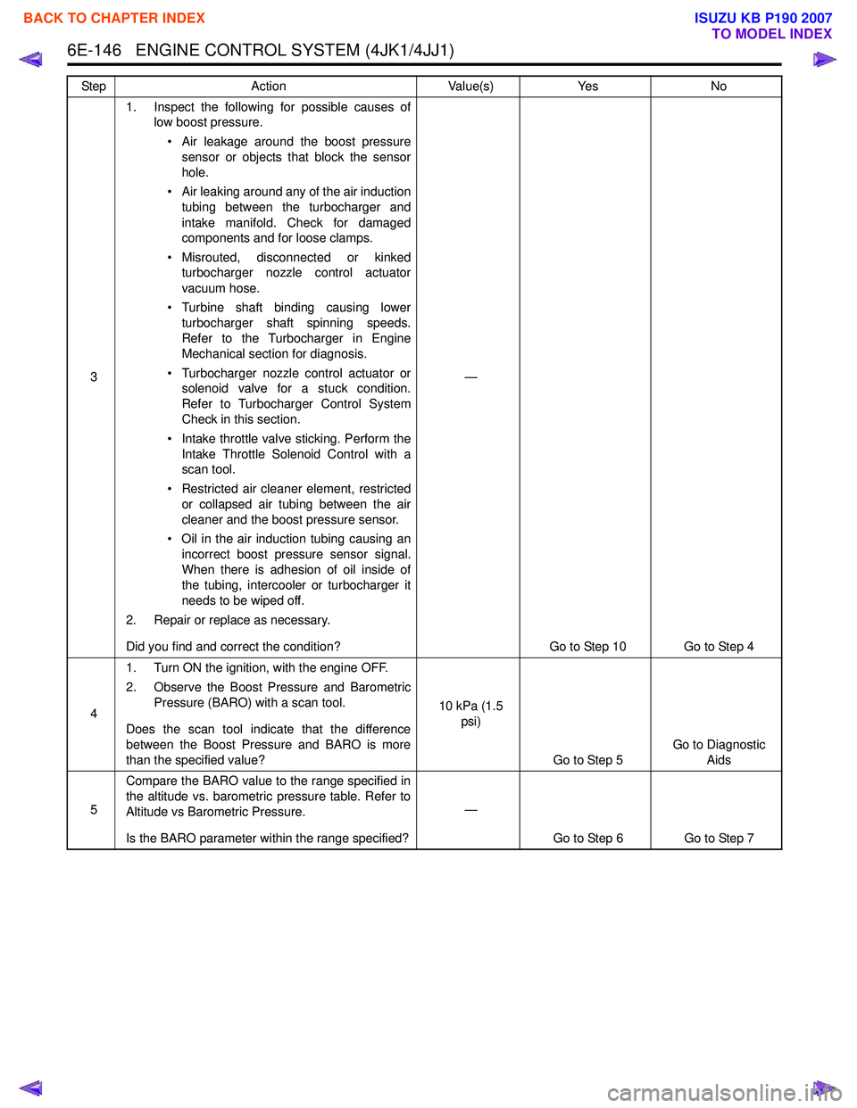
6E-146 ENGINE CONTROL SYSTEM (4JK1/4JJ1)
31. Inspect the following for possible causes of
low boost pressure.
• Air leakage around the boost pressure sensor or objects that block the sensor
hole.
• Air leaking around any of the air induction tubing between the turbocharger and
intake manifold. Check for damaged
components and for loose clamps.
• Misrouted, disconnected or kinked turbocharger nozzle control actuator
vacuum hose.
• Turbine shaft binding causing lower turbocharger shaft spinning speeds.
Refer to the Turbocharger in Engine
Mechanical section for diagnosis.
• Turbocharger nozzle control actuator or solenoid valve for a stuck condition.
Refer to Turbocharger Control System
Check in this section.
• Intake throttle valve sticking. Perform the Intake Throttle Solenoid Control with a
scan tool.
• Restricted air cleaner element, restricted or collapsed air tubing between the air
cleaner and the boost pressure sensor.
• Oil in the air induction tubing causing an incorrect boost pressure sensor signal.
When there is adhesion of oil inside of
the tubing, intercooler or turbocharger it
needs to be wiped off.
2. Repair or replace as necessary.
Did you find and correct the condition? —
Go to Step 10 Go to Step 4
4 1. Turn ON the ignition, with the engine OFF.
2. Observe the Boost Pressure and Barometric Pressure (BARO) with a scan tool.
Does the scan tool indicate that the difference
between the Boost Pressure and BARO is more
than the specified value? 10 kPa (1.5
psi)
Go to Step 5 Go to Diagnostic
Aids
5 Compare the BARO value to the range specified in
the altitude vs. barometric pressure table. Refer to
Altitude vs Barometric Pressure.
Is the BARO parameter within the range specified? —
Go to Step 6 Go to Step 7
Step
Action Value(s)Yes No
BACK TO CHAPTER INDEX
TO MODEL INDEX
ISUZU KB P190 2007