2007 ISUZU KB P190 vacuum
[x] Cancel search: vacuumPage 1517 of 6020
ENGINE MECHANICAL (4JK1/4JJ1) 6A-157
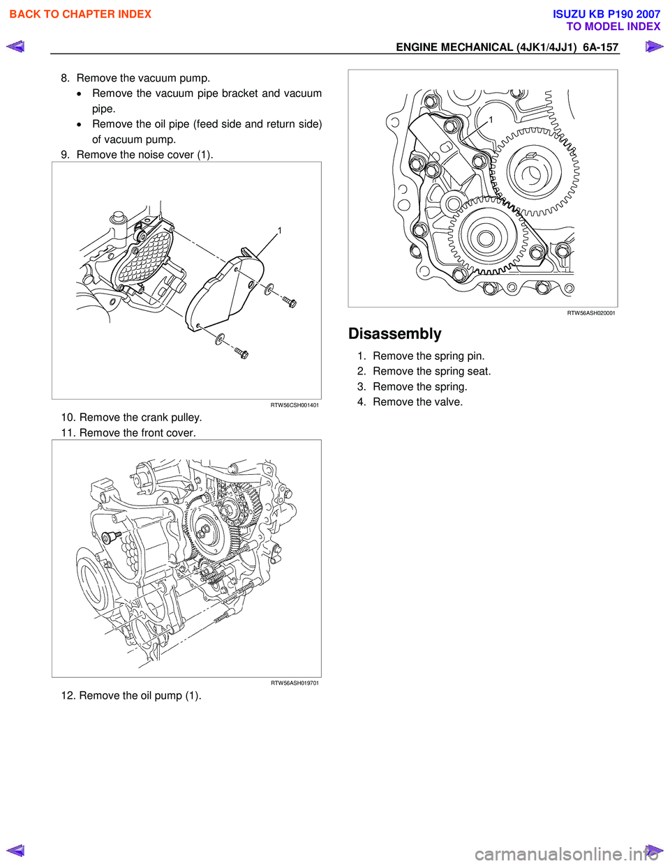
8. Remove the vacuum pump.
• Remove the vacuum pipe bracket and vacuum
pipe.
• Remove the oil pipe (feed side and return side)
of vacuum pump.
9. Remove the noise cover (1).
RTW 56CSH001401
10. Remove the crank pulley.
11. Remove the front cover.
RTW 56ASH019701
12. Remove the oil pump (1).
RTW 56ASH020001
Disassembly
1. Remove the spring pin.
2. Remove the spring seat.
3. Remove the spring.
4. Remove the valve.
BACK TO CHAPTER INDEX
TO MODEL INDEX
ISUZU KB P190 2007
Page 1520 of 6020
6A-160 ENGINE MECHANICAL (4JK1/4JJ1)
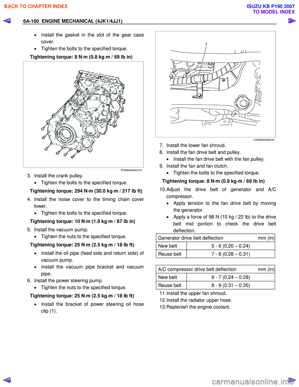
• Install the gasket in the slot of the gear case
cover.
• Tighten the bolts to the specified torque.
Tightening torque: 8 N ⋅
⋅⋅
⋅
m (0.8 kg ⋅
⋅⋅
⋅
m / 69 lb in)
RTW 56ASH012101
3. Install the crank pulley.
• Tighten the bolts to the specified torque.
Tightening torque: 294 N ⋅
⋅⋅
⋅
m (30.0 kg ⋅
⋅⋅
⋅
m / 217 lb ft)
4. Install the noise cover to the timing chain cove
r
lower.
• Tighten the bolts to the specified torque.
Tightening torque: 10 N ⋅
⋅⋅
⋅
m (1.0 kg ⋅
⋅⋅
⋅
m / 87 lb in)
5. Install the vacuum pump. • Tighten the nuts to the specified torque.
Tightening torque: 25 N ⋅
⋅⋅
⋅
m (2.5 kg ⋅
⋅⋅
⋅
m / 18 lb ft)
• Install the oil pipe (feed side and return side) o
f
vacuum pump.
• Install the vacuum pipe bracket and vacuum
pipe.
6. Install the power steering pump. • Tighten the nuts to the specified torque.
Tightening torque: 25 N ⋅
⋅⋅
⋅
m (2.5 kg ⋅
⋅⋅
⋅
m / 18 lb ft)
• Install the bracket of power steering oil hose
clip (1).
LTW 56ASH000101
7. Install the lower fan shroud.
8. Install the fan drive belt and pulley. • Install the fan drive belt with the fan pulley.
9. Install the fan and fan clutch. • Tighten the bolts to the specified torque.
Tightening torque: 8 N ⋅
⋅⋅
⋅
m (0.8 kg ⋅
⋅⋅
⋅
m / 69 lb in)
10.
Adjust the drive belt of generator and A/C
compressor.
• Apply tension to the fan drive belt by moving
the generator.
•
Apply a force of 98 N (10 kg / 22 lb) to the drive
belt mid portion to check the drive belt
deflection.
Generator drive belt deflection mm (in)
New belt 5 - 6 (0.20 – 0.24)
Reuse belt 7 - 8 (0.28 – 0.31)
A/C compressor drive belt deflection mm (in)
New belt 6 - 7 (0.24 – 0.28)
Reuse belt 8 - 9 (0.31 – 0.35)
11. Install the upper fan shroud.
12. Install the radiator upper hose.
13. Replenish the engine coolant.
BACK TO CHAPTER INDEX
TO MODEL INDEX
ISUZU KB P190 2007
Page 1538 of 6020
ENGINE COOLING (4JK1/4JJ1) 6B-15
Inspection and Repair
Make the necessary adjustments, repairs, and part
replacements if excessive wear or damage is
discovered during inspection.
Radiator Cap
Measure the valve opening pressure of the pressurizing
valve with a radiator filler cap tester.
Replace the cap if the valve opening pressure is outside
the standard range.
Valve opening pressure: 93.3 - 122.7 kPa (0.95 - 1.25 kg / cm
2 / 13.5 -
17.8 psi)
Cap tester: 5–8840–0277–0
Adapter: 5–8840–2603–0
Check the condition of the vacuum valve in the cente
r
of the valve seat side of the cap. If considerable rust or
dirt is found, or if the valve seat cannot be moved by
hand, clean or replace the cap.
Valve opening vacuum: 1.96 - 4.91 kPa (0.02 - 0.05 kg / cm
2 / 0.28 - 0.71
psi)
110RS006
Radiator Core
1. A bent fin may result in reduced ventilation and
overheating may occur. All bent fins must be
straightened. Pay close attention to the base of the
fin when it is being straightened.
2. Remove all dust, bugs and other foreign material.
Flushing the Radiator
Thoroughly wash the inside of the radiator and the
engine coolant passages with cold water and mild
detergent. Remove all signs of scale and rust.
Cooling System Leakage Check
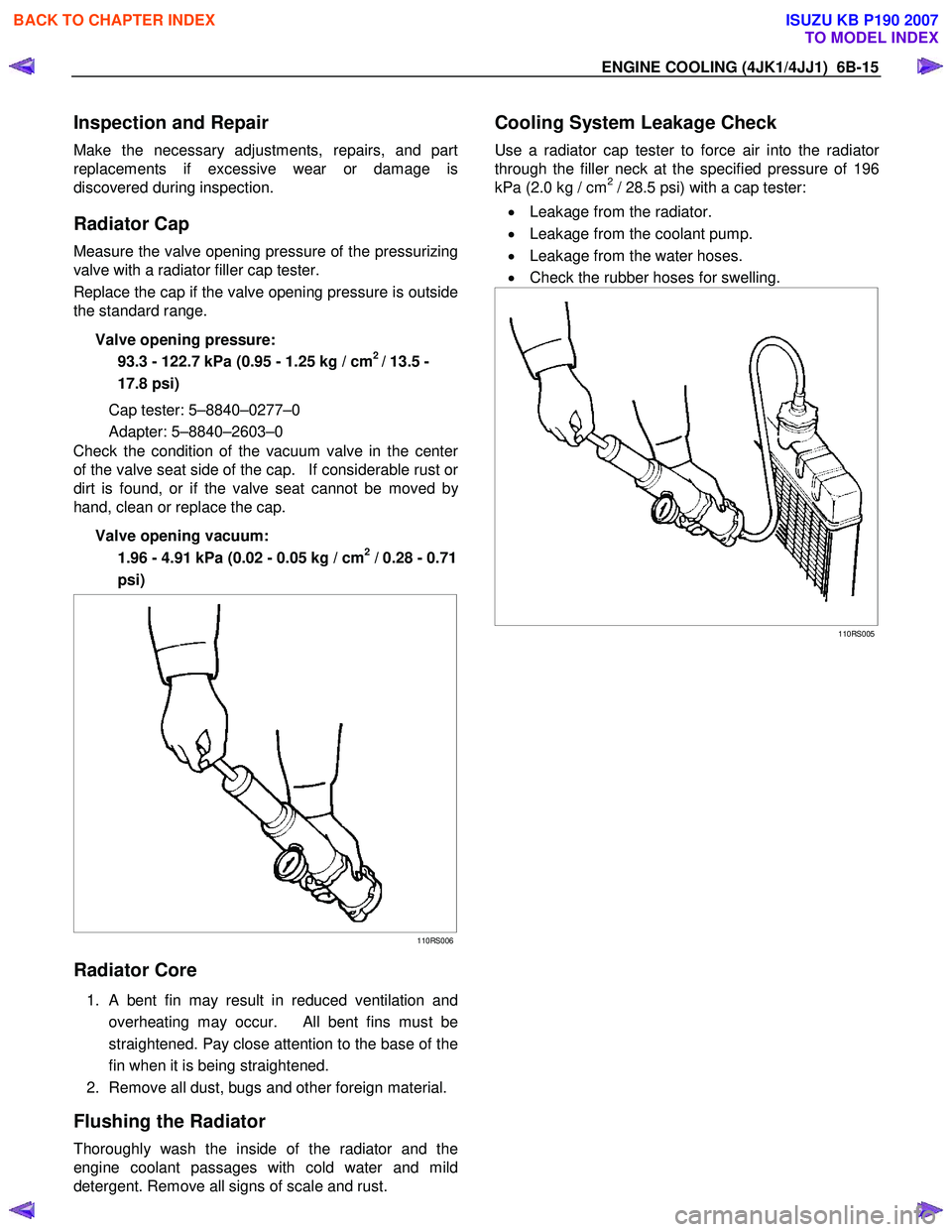
Use a radiator cap tester to force air into the radiator
through the filler neck at the specified pressure of 196
kPa (2.0 kg / cm2 / 28.5 psi) with a cap tester:
• Leakage from the radiator.
• Leakage from the coolant pump.
• Leakage from the water hoses.
• Check the rubber hoses for swelling.
110RS005
BACK TO CHAPTER INDEX
TO MODEL INDEX
ISUZU KB P190 2007
Page 1564 of 6020
FUEL SYSTEM (4JK1/4JJ1) 6C-23
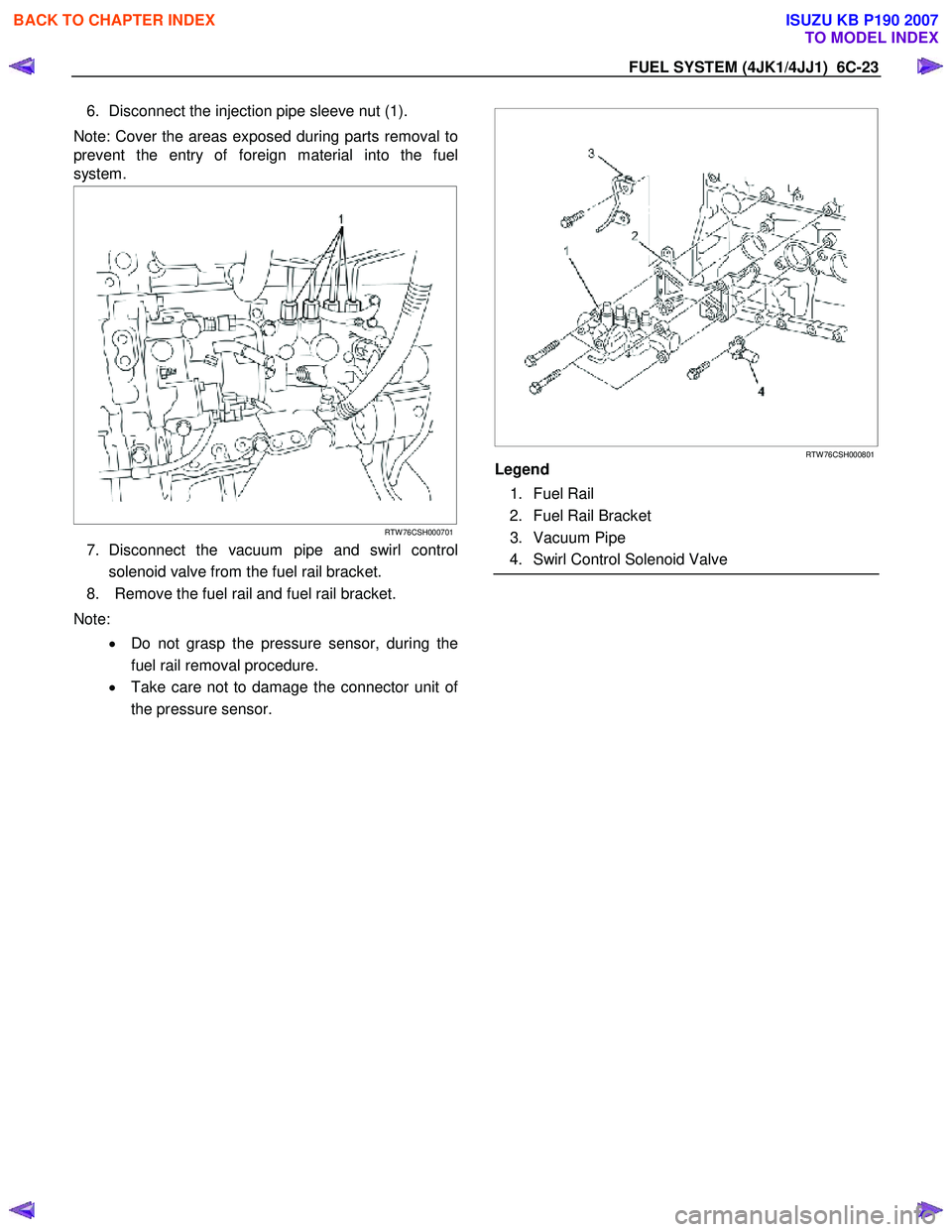
6. Disconnect the injection pipe sleeve nut (1).
Note: Cover the areas exposed during parts removal to
prevent the entry of foreign material into the fuel
system.
RTW 76CSH000701
7. Disconnect the vacuum pipe and swirl control
solenoid valve from the fuel rail bracket.
8. Remove the fuel rail and fuel rail bracket.
Note: • Do not grasp the pressure sensor, during the
fuel rail removal procedure.
• Take care not to damage the connector unit o
f
the pressure sensor.
RTW 76CSH000801
Legend
1. Fuel Rail
2. Fuel Rail Bracket
3. Vacuum Pipe
4. Swirl Control Solenoid Valve
BACK TO CHAPTER INDEX
TO MODEL INDEX
ISUZU KB P190 2007
Page 1565 of 6020
6C-24 FUEL SYSTEM (4JK1/4JJ1)
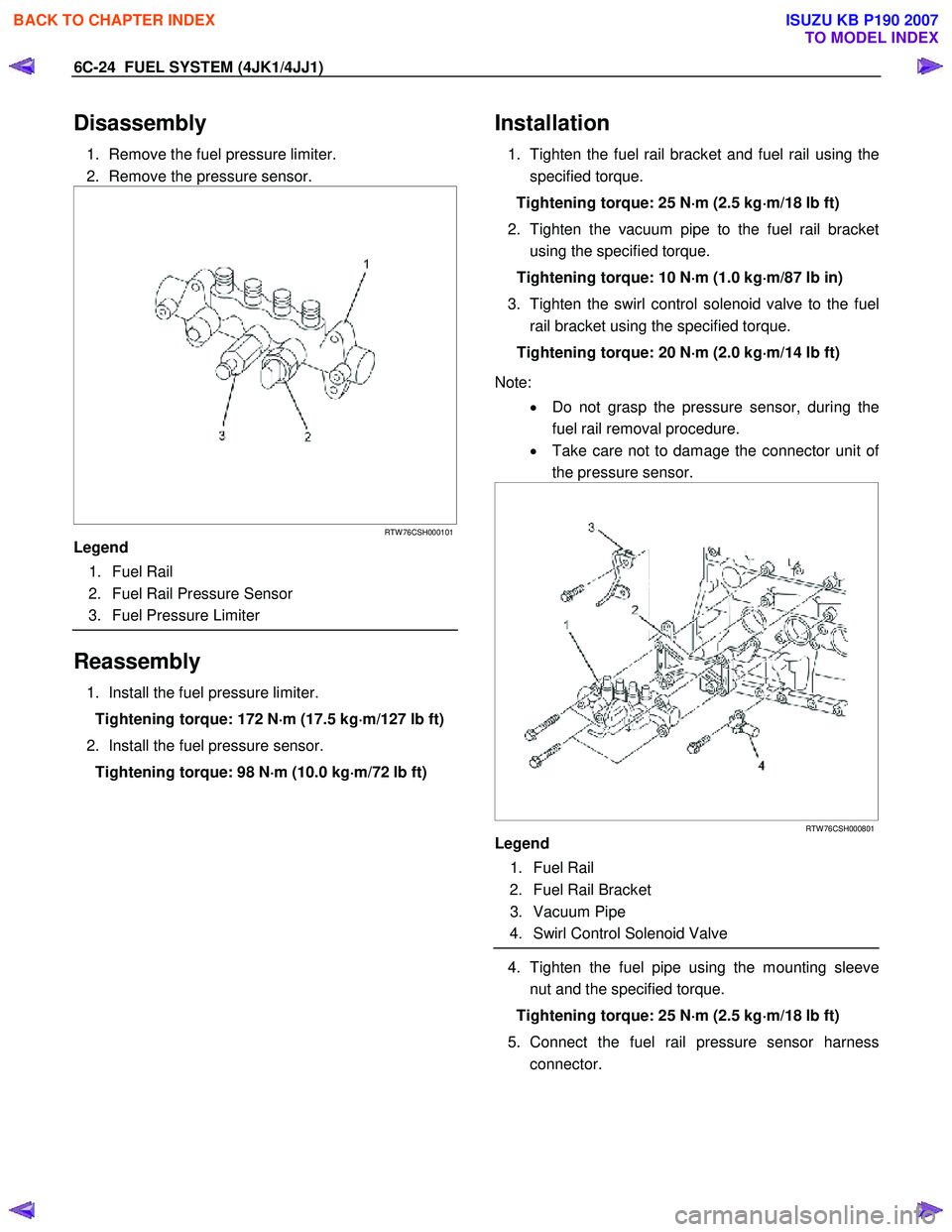
Disassembly
1. Remove the fuel pressure limiter.
2. Remove the pressure sensor.
RTW 76CSH000101
Legend
1. Fuel Rail
2. Fuel Rail Pressure Sensor
3. Fuel Pressure Limiter
Reassembly
1. Install the fuel pressure limiter.
Tightening torque: 172 N ⋅
⋅⋅
⋅
m (17.5 kg ⋅
⋅⋅
⋅
m/127 lb ft)
2. Install the fuel pressure sensor. Tightening torque: 98 N ⋅
⋅⋅
⋅
m (10.0 kg ⋅
⋅⋅
⋅
m/72 lb ft)
Installation
1. Tighten the fuel rail bracket and fuel rail using the
specified torque.
Tightening torque: 25 N ⋅
⋅⋅
⋅
m (2.5 kg ⋅
⋅⋅
⋅
m/18 lb ft)
2. Tighten the vacuum pipe to the fuel rail bracket using the specified torque.
Tightening torque: 10 N ⋅
⋅⋅
⋅
m (1.0 kg ⋅
⋅⋅
⋅
m/87 lb in)
3. Tighten the swirl control solenoid valve to the fuel rail bracket using the specified torque.
Tightening torque: 20 N ⋅
⋅⋅
⋅
m (2.0 kg ⋅
⋅⋅
⋅
m/14 lb ft)
Note: • Do not grasp the pressure sensor, during the
fuel rail removal procedure.
• Take care not to damage the connector unit o
f
the pressure sensor.
RTW 76CSH000801
Legend
1. Fuel Rail
2. Fuel Rail Bracket
3. Vacuum Pipe
4. Swirl Control Solenoid Valve
4. Tighten the fuel pipe using the mounting sleeve
nut and the specified torque.
Tightening torque: 25 N ⋅
⋅⋅
⋅
m (2.5 kg ⋅
⋅⋅
⋅
m/18 lb ft)
5. Connect the fuel rail pressure sensor harness connector.
BACK TO CHAPTER INDEX
TO MODEL INDEX
ISUZU KB P190 2007
Page 1588 of 6020
FUEL SYSTEM (4JK1/4JJ1) 6C-47
Fuel Filler Cap
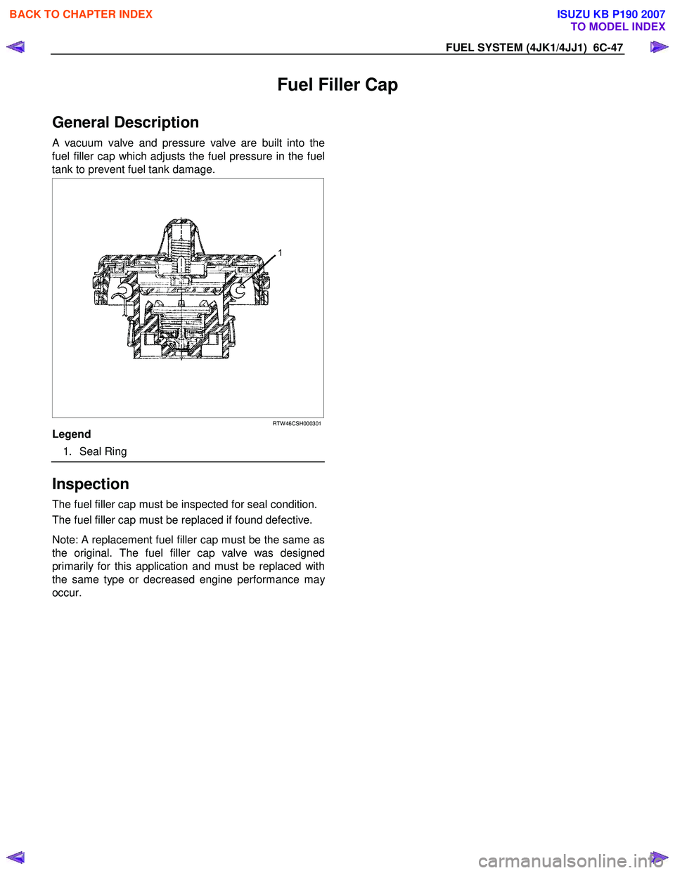
General Description
A vacuum valve and pressure valve are built into the
fuel filler cap which adjusts the fuel pressure in the fuel
tank to prevent fuel tank damage.
RTW 46CSH000301
Legend
1. Seal Ring
Inspection
The fuel filler cap must be inspected for seal condition.
The fuel filler cap must be replaced if found defective.
Note: A replacement fuel filler cap must be the same as
the original. The fuel filler cap valve was designed
primarily for this application and must be replaced with
the same type or decreased engine performance ma
y
occur.
BACK TO CHAPTER INDEX
TO MODEL INDEX
ISUZU KB P190 2007
Page 1618 of 6020

ENGINE CONTROL SYSTEM (4JK1/4JJ1) 6E-1
SECTION 6E
ENGINE CONTROL SYSTEM(4JK1/4JJ1)
TABLE OF CONTENTS
Specifications . . . . . . . . . . . . . . . . . . . . . . . . . . . . 6E-3 Temperature vs Resistance . . . . . . . . . . . . . . . . 6E-3
Altitude vs Barometric Pressure . . . . . . . . . . . . . 6E-3
Diagnostic Trouble Code (DTC) Type Definitions . . . . . . . . . . . . . . . . . . . . . . . . . . . . . 6E-4
Diagnostic Trouble Code (DTC) List . . . . . . . . . 6E-4
Schematic and Rounting Diagrams. . . . . . . . . . . . 6E-9 Fuel System Routing Diagram . . . . . . . . . . . . . . 6E-9
Vacuum Hose Routing Diagram . . . . . . . . . . . . . 6E-9
Engine Controls Schematics . . . . . . . . . . . . . . 6E-10
Component Locator. . . . . . . . . . . . . . . . . . . . . . . 6E-27 Engine Controls Component Views . . . . . . . . . 6E-27
Engine Control Module (ECM) Connector End Views . . . . . . . . . . . . . . . . . . . . . . . . . . . . 6E-30
Engine Control Connector End Views . . . . . . . 6E-33
Diagnostic Information and Procedures . . . . . . . 6E-42 Engine Control System Check Sheet . . . . . . . . 6E-42
Diagnostic Starting Point - Engine Controls . . . 6E-43
Diagnostic System Check - Engine Controls . . 6E-44
Scan Tool Data List . . . . . . . . . . . . . . . . . . . . . 6E-46
Scan Tool Data Definitions . . . . . . . . . . . . . . . . 6E-49
Scan Tool Output Controls . . . . . . . . . . . . . . . . 6E-54
Scan Tool Does Not Power Up. . . . . . . . . . . . . 6E-55
Scan Tool Does Not Communicate with CAN Device. . . . . . . . . . . . . . . . . . . . . . . . . . . 6E-56
Lost Communication with The Engine Control Module (ECM) . . . . . . . . . . . . . . . . . . 6E-59
Engine Cranks but Does Not Run . . . . . . . . . . 6E-62
DTC P0016 (Flash Code 16) . . . . . . . . . . . . . . 6E-68
DTC P0045 (Flash Code 33) . . . . . . . . . . . . . . 6E-70
DTC P0087 (Flash Code 225) . . . . . . . . . . . . . 6E-72
DTC P0088 (Flash Code 118) . . . . . . . . . . . . . 6E-77
DTC P0089 (Flash Code 151) . . . . . . . . . . . . . 6E-82
DTC P0091 or P0092 (Flash Code 247) . . . . . 6E-85
DTC P0093 (Flash Code 227) . . . . . . . . . . . . . 6E-88
DTC P0101 (Flash Code 92) . . . . . . . . . . . . . . 6E-93
DTC P0102 or P0103 (Flash Code 91) . . . . . . 6E-96
DTC P0107 or P0108 (Flash Code 32) . . . . . 6E-100
DTC P0112 or P0113 (Flash Code 22) . . . . . 6E-104
DTC P0116 (Flash Code 23) . . . . . . . . . . . . . 6E-108
DTC P0117 or P0118 (Flash Code 23) . . . . . 6E-110
DTC P0122 or P0123 (Flash Code 43) . . . . . 6E-114
DTC P0182 or P0183 (Flash Code 211) . . . . 6E-118
DTC P0192 or P0193 (Flash Code 245) . . . . 6E-122
DTC P0201, P0202, P0203 or P0204 (Flash Code 271, 272, 273 or 274) . . . . . . . . 6E-126
DTC P0217 (Flash Code 542) . . . . . . . . . . . . 6E-133
DTC P0219 (Flash Code 543) . . . . . . . . . . . . 6E-135
DTC P0231 or P0232 (Flash Code 69) . . . . . 6E-137
DTC P0234 (Flash Code 42) . . . . . . . . . . . . . 6E-140 DTC P0299 (Flash Code 65) . . . . . . . . . . . . . 6E-143
DTC P0335 (Flash Code 15) . . . . . . . . . . . . . 6E-146
DTC P0336 (Flash Code 15) . . . . . . . . . . . . . 6E-149
DTC P0340 (Flash Code 14) . . . . . . . . . . . . . 6E-151
DTC P0341 (Flash Code 14) . . . . . . . . . . . . . 6E-154
DTC P0380 (Flash Code 66) . . . . . . . . . . . . . 6E-156
DTC P0401 (Flash Code 93) . . . . . . . . . . . . . 6E-159
DTC P0403 (Flash Code 37) . . . . . . . . . . . . . 6E-161
DTC P0404 (Flash Code 45) . . . . . . . . . . . . . 6E-164
DTC P0405 or P0406 (Flash Code 44) . . . . . 6E-166
DTC P0500 (Flash Code 25) . . . . . . . . . . . . . 6E-170
DTC P0501 (Flash Code 25) . . . . . . . . . . . . . 6E-174
DTC P0512 (Flash Code 417) . . . . . . . . . . . . 6E-176
DTC P0562 or P0563 (Flash Code 35) . . . . . 6E-178
DTC P0565 (Flash Code 515) . . . . . . . . . . . . 6E-181
DTC P0566 (Flash Code 516) . . . . . . . . . . . . 6E-183
DTC P0567 (Flash Code 517) . . . . . . . . . . . . 6E-185
DTC P0568 (Flash Code 518) . . . . . . . . . . . . 6E-187
DTC P0571 (Flash Code 26) . . . . . . . . . . . . . 6E-189
DTC P0601 (Flash Code 53) . . . . . . . . . . . . . 6E-192
DTC P0602 (Flash Code 154) . . . . . . . . . . . . 6E-193
DTC P0604 or P0606 (Flash Code 153 or 51) . . . . . . . . . . . . . . . . . 6E-195
DTC P0615 (Flash Code 19) . . . . . . . . . . . . . 6E-196
DTC P0633 (Flash Code 176) . . . . . . . . . . . . 6E-198
DTC P0638 (Flash Code 61) . . . . . . . . . . . . . 6E-199
DTC P0642 or P0643 (Flash Code 55) . . . . . 6E-201
DTC P0650 (Flash Code 77) . . . . . . . . . . . . . 6E-204
DTC P0652 or P0653 (Flash Code 56) . . . . . 6E-207
DTC P0661 or P0662 (Flash Code 58) . . . . . 6E-211
DTC P0698 or P0699 (Flash Code 57) . . . . . 6E-215
DTC P0700 (Flash Code 185) . . . . . . . . . . . . 6E-219
DTC P1064 or P1065 (Flash Code 247) . . . . 6E-220
DTC P1093 (Flash Code 227) . . . . . . . . . . . . 6E-224
DTC P1094 (Flash Code 226) . . . . . . . . . . . . 6E-229
DTC P1196, P1197 or P1198 (Flash Code 461) . . . . . . . . . . . . . . . . . . . . . 6E-235
DTC P124B (Flash Code 157) . . . . . . . . . . . . 6E-237
DTC P1261 (Flash Code 34) . . . . . . . . . . . . . 6E-240
DTC P1262 (Flash Code 34) . . . . . . . . . . . . . 6E-242
DTC P1404 (Flash Code 45) . . . . . . . . . . . . . 6E-244
DTC P1411, P1412 or P1413 (Flash Code 445) . . . . . . . . . . . . . . . . . . . . . 6E-246
DTC P156A or P156B (Flash Code 135) . . . . 6E-248
DTC P161B (Flash Code 179) . . . . . . . . . . . . 6E-251
DTC P1621 (Flash Code 54, 254) . . . . . . . . . 6E-253
DTC P1664 (Flash Code 76) . . . . . . . . . . . . . 6E-255
DTC P2100, P2101 or P2103 (Flash Code 446) . . . . . . . . . . . . . . . . . . . . . 6E-258
DTC P2122 or P2123 (Flash Code 121) . . . . 6E-261
BACK TO CHAPTER INDEX
TO MODEL INDEX
ISUZU KB P190 2007
Page 1626 of 6020
ENGINE CONTROL SYSTEM (4JK1/4JJ1) 6E-9
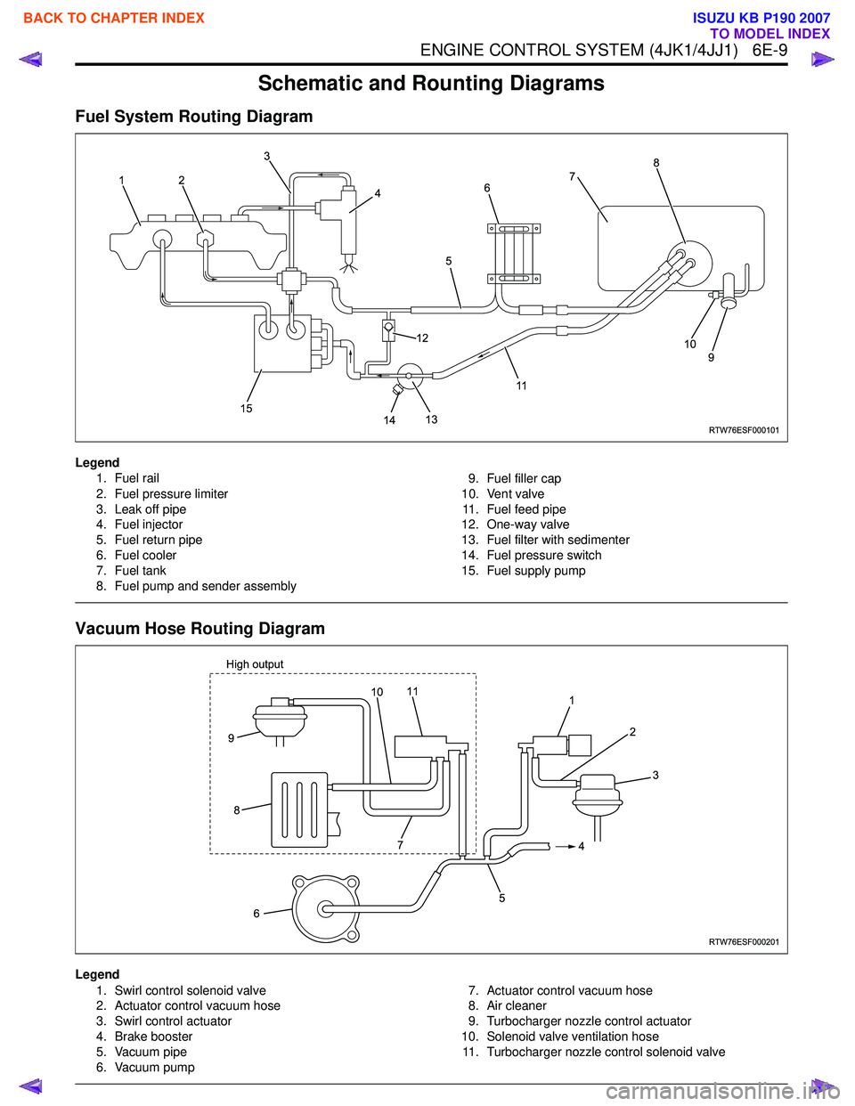
Schematic and Rounting Diagrams
Fuel System Routing Diagram
Legend1. Fuel rail
2. Fuel pressure limiter
3. Leak off pipe
4. Fuel injector
5. Fuel return pipe
6. Fuel cooler
7. Fuel tank
8. Fuel pump and sender assembly 9. Fuel filler cap
10. Vent valve 11. Fuel feed pipe
12. One-way valve
13. Fuel filter with sedimenter
14. Fuel pressure switch
15. Fuel supply pump
Vacuum Hose Routing Diagram
Legend
1. Swirl control solenoid valve
2. Actuator control vacuum hose
3. Swirl control actuator
4. Brake booster
5. Vacuum pipe
6. Vacuum pump 7. Actuator control vacuum hose
8. Air cleaner
9. Turbocharger nozzle control actuator
10. Solenoid valve ventilation hose 11. Turbocharger nozzle control solenoid valve
RTW76ESF000101
12 3
4
5
117
8
9
10
14
13
12
15
6
RTW76ESF000201
1 2
4
5
6
9
8
3
7
11
High output10
BACK TO CHAPTER INDEX
TO MODEL INDEX
ISUZU KB P190 2007