2007 ISUZU KB P190 vacuum
[x] Cancel search: vacuumPage 3234 of 6020
Fuel System – V6 Page 6C – 32
4.8 Fuel Filler Cap
The fuel filler cap is a 'screw on' type, with an integrated tightening torque limiting mechanism. W hen installing the fuel
filler cap, tighten it until a ratcheting (clicking) sound is audible, indicating the fuel filler cap is properly tightened. Th e fuel
filler cap is tethered to the fuel filler pocket.
Remove
The fuel filler cap requires a quarter of a turn anticlockwise to be removed.
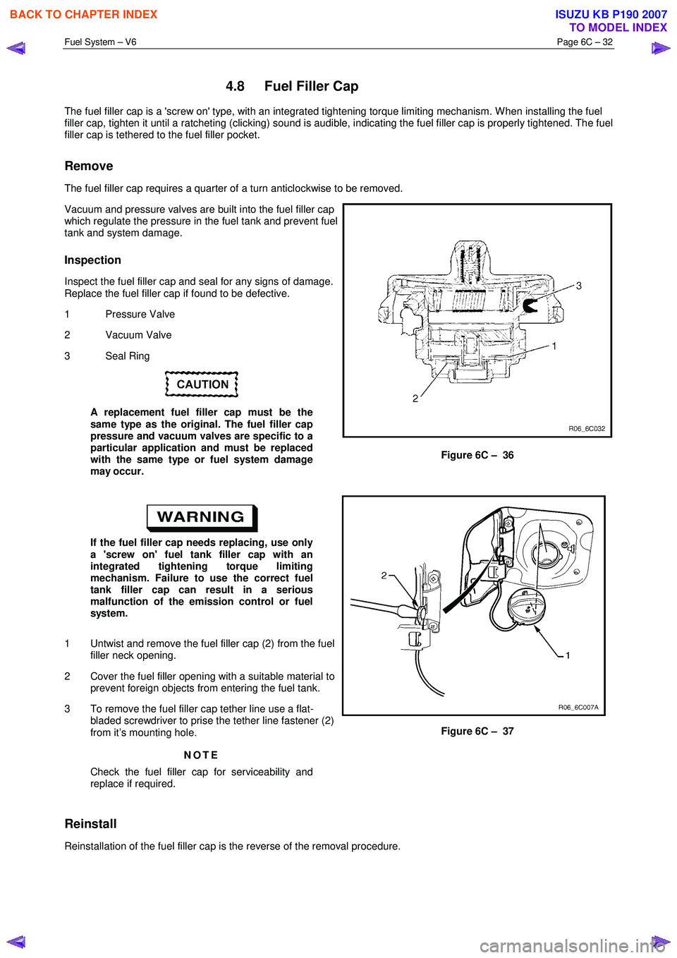
Vacuum and pressure valves are built into the fuel filler cap
which regulate the pressure in the fuel tank and prevent fuel
tank and system damage.
Inspection
Inspect the fuel filler cap and seal for any signs of damage.
Replace the fuel filler cap if found to be defective.
1 Pressure Valve
2 Vacuum Valve
3 Seal Ring
A replacement fuel filler cap must be the
same type as the original. The fuel filler cap
pressure and vacuum valves are specific to a
particular application and must be replaced
with the same type or fuel system damage
may occur.
Figure 6C – 36
If the fuel filler cap needs replacing, use only
a 'screw on' fuel tank filler cap with an
integrated tightening torque limiting
mechanism. Failure to use the correct fuel
tank filler cap can result in a serious
malfunction of the emission control or fuel
system.
1 Untwist and remove the fuel filler cap (2) from the fuel filler neck opening.
2 Cover the fuel filler opening with a suitable material to prevent foreign objects from entering the fuel tank.
3 To remove the fuel filler cap tether line use a flat- bladed screwdriver to prise the tether line fastener (2)
from it’s mounting hole.
NOTE
Check the fuel filler cap for serviceability and
replace if required.
Figure 6C – 37
Reinstall
Reinstallation of the fuel filler cap is the reverse of the removal procedure.
BACK TO CHAPTER INDEX
TO MODEL INDEX
ISUZU KB P190 2007
Page 3242 of 6020
Fuel System – V6 Page 6C – 40
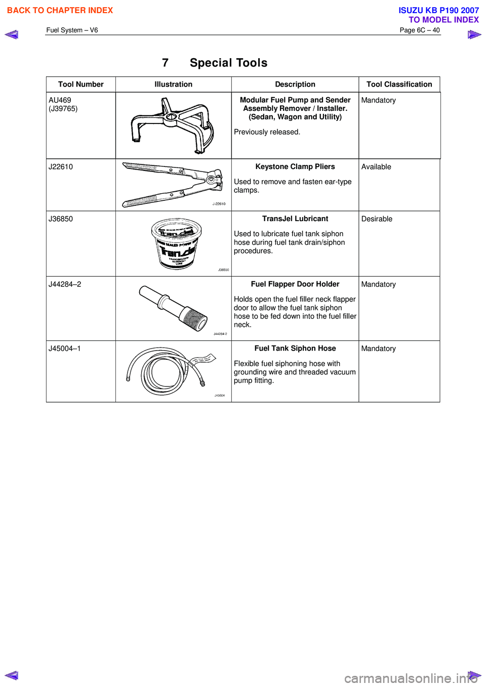
7 Special Tools
Tool Number Illustration Description Tool Classification
AU469
(J39765)
Modular Fuel Pump and Sender
Assembly Remover / Installer.
(Sedan, Wagon and Utility)
Previously released. Mandatory
J22610 Keystone Clamp Pliers
Used to remove and fasten ear-type
clamps. Available
J36850 TransJel Lubricant
Used to lubricate fuel tank siphon
hose during fuel tank drain/siphon
procedures. Desirable
J44284–2 Fuel Flapper Door Holder
Holds open the fuel filler neck flapper
door to allow the fuel tank siphon
hose to be fed down into the fuel filler
neck. Mandatory
J45004–1 Fuel Tank Siphon Hose
Flexible fuel siphoning hose with
grounding wire and threaded vacuum
pump fitting. Mandatory
BACK TO CHAPTER INDEX
TO MODEL INDEX
ISUZU KB P190 2007
Page 3278 of 6020
Engine Management – V6 – General Information Page 6C1-1–36
Intermittent
An electrical signal that occurs now and then; not continuously. In electrical circuits, refers to occasional open,
short, or ground in a circuit
Light Throttle Approximately 1/4 of accelerator pedal travel (25% throttle position)
Low
A voltage less than a specific threshold. Operates the same as a ground and may, or may not, be connected
to chassis ground.
MAF Sensor Mass Air Flow Sensor. A device that provides a variable voltage to the ECM based on the amount of air flow
entering in the intake system.
Medium Throttle Approximately 1/2 of accelerator pedal travel (50% throttle position)
N.C Normally Closed. Switch contacts that are closed when they are in the normal operating position
N.O Normally Open. Switch contacts that are normally open when in the normal operating position
NOx
Nitrogen Oxide. One of the pollutants found in spark ignition engine exhaust that is formed from normal
combustion and increases in severity with combustion temperature.
O2 Sensor Oxygen Sensor. A device located in the exhaust system that provides a variable voltage to the ECM based on
the oxygen content of exhaust gas.
May also include a heating circuit to provide faster initial warm-up (HO2 sensor).
OBD On Board Diagnostic
Open Loop ECM control of the fuel control system without the use of the oxygen sensor signal.
Output Functions that are controlled by the ECM, typically these can include solenoids and relays, etc.
ECM Engine Control Module. An electronic device which controls the engine management system.
ECU Electronic Control Unit. An electronic device which controls specific system functions
PCV
Positive Crankcase Ventilation. Method of reburning crankcase fumes rather than passing them directly into
the atmosphere
PIM Powertrain Interface Module – The PIM acts as a communication translator between the ECM and other on-
board controllers that use a different serial data protocol.
PM Permanent Magnet
PWM
Pulse Width Modulated. A digital signal turned on and off for a percentage of available cycle time. A signal that
is 30% on and 70% of would be termed a 30% on PWM signal.
Quad Driver A transistor in the ECM capable of operating four separate outputs. Outputs can be either on-off or pulse width
modulated.
RAM Random Access Memory. A microprocessor can write into or read from this memory as needed. This memory
is volatile and needs a constant power supply to be retained. If the power is lost or removed, RAM data is lost.
r.p.m. Revolutions Per Minute
Serial Data
Serial data is a series of rapidly changing voltage signals pulsed from high to low. These signals are typically
transmitted through a wire often referred to as the Serial Data Circuit.
SFI Sequential Fuel Injection. Method of injecting fuel into the engine one cylinder at a time in relation to the
engines firing order.
Solenoid An electromagnetic coil which creates a magnetic field when current is applied, causing a plunger or ball to
move.
Switch Device to opens and close a circuit, thereby controlling current flow.
Tech 2
Tech 2 is a peripheral device that aids in the diagnosis and repair of electronic systems such as engine
management, transmission control etc. Tech 2 connects to the vehicle’s Data Link Connector (DLC).
TP Sensor Throttle Position sensor. A device that provides a variable voltage to the ECM based on the position of the
throttle plate.
Vacuum – manifold Vacuum sourced downstream of the throttle plate.
Vacuum – ported Vacuum sourced upstream of the throttle plate.
VSS Vehicle Speed Sensor. A permanent magnet type device that provides a digital voltage to the ECM.
WOT Wide Open Throttle – Full travel of the accelerator pedal (100% throttle position).
BACK TO CHAPTER INDEX
TO MODEL INDEX
ISUZU KB P190 2007
Page 3298 of 6020
Engine Management – V6 – Diagnostics Page 6C1-2–20
• Ensure the resistance between the ECM housing and the battery negative cable is less than 0.5 Ω.
• Check the ECM bracket fasteners for correct torque value.
• Check all engine management related components for correct installation.
• Inspect the vacuum hoses for splits, kinks, oil contamination and proper connections, refer to the vehicle emission
control information label. Check the hoses thoroughly for any type of leak or restriction.
• Inspect the air intake ducts for being collapsed, split or for having damaged areas.
• Inspect for air leaks at the throttle body mounting area, mass air flow (MAF) sensor, intake manifold and intake
manifold sealing surfaces.
• Check for wiring harness routing that may be positioned too close to a high voltage or high current device such as
the following:
− Secondary ignition components, and
− Motors and generators.
NOTE
High voltage or high current devices may induce
electrical noise on a circuit, which can interfere
with normal circuit operation.
4.4 Diagnostic System Check
Description
The engine management diagnostic procedure is organised in a logical structure that begins with the Diagnostic System
Check. The Diagnostic System Check directs the diagnostic procedure to the logical steps necessary to diagnose an
engine driveability fault condition.
Test Description
The following numbers refer to the step numbers in the diagnostic table:
6 Tests the integrity of the GM LAN serial data communication circuit. A PIM DTC sets if the PIM detects a fault condition in the communication circuit. A fault condition on the serial data communication circuit may trigger
multiple DTCs on other sensors and components.
Step Action Yes No
1 Have you read the basic requirements?
Go to Step 2 Refer to
4.1 Basic
Requirements
2 Have you read the diagnostic precautions?
Go to Step 3 Refer to
4.2 Diagnostic Precautions
3 Have you performed the preliminary checks?
Go to Step 4 Refer to
4.3 Preliminary Checks
4 Using Tech 2, attempt to communicate with the PIM.
Does the PIM fail to communicate? Refer to 6E1
Powertrain Interface Module – V6 Go to Step 5
5 Does DTC B3902, C0550, U2100, U2105, U2106, P0633, or P1611
also set in the PIM? Refer to 6E1
Powertrain Interface Module – V6 Go to Step 6
6 Using Tech 2, view and record DTCs set at the ECM and TCM.
Does Tech 2 display any DTC? Go to Step 7 Refer to
5.1 Symptoms
Diagnosis Table
BACK TO CHAPTER INDEX
TO MODEL INDEX
ISUZU KB P190 2007
Page 3305 of 6020
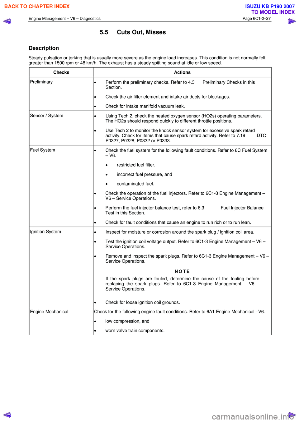
Engine Management – V6 – Diagnostics Page 6C1-2–27
5.5 Cuts Out, Misses
Description
Steady pulsation or jerking that is usually more severe as the engine load increases. This condition is not normally felt
greater than 1500 rpm or 48 km/h. The exhaust has a steady spitting sound at idle or low speed.
Checks Actions
Preliminary • Perform the preliminary checks. Refer to 4.3 Preliminary Checks in this
Section.
• Check the air filter element and intake air ducts for blockages.
• Check for intake manifold vacuum leak.
Sensor / System
• Using Tech 2, check the heated oxygen sensor (HO2s) operating parameters.
The HO2s should respond quickly to different throttle positions.
• Use Tech 2 to monitor the knock sensor system for excessive spark retard
activity. Check for items that cause spark retard activity. Refer to 7.19 DTC
P0327, P0328, P0332 or P0333.
Fuel System • Check the fuel system for the following fault conditions. Refer to 6C Fuel System
– V6.
• restricted fuel filter,
• incorrect fuel pressure, and
• contaminated fuel.
• Check the operation of the fuel injectors. Refer to 6C1-3 Engine Management –
V6 – Service Operations.
• Perform the fuel injector balance test, refer to 6.3 Fuel Injector Balance
Test in this Section.
• Check for fault conditions that cause an engine to run rich or to run lean.
Ignition System
• Inspect for moisture or corrosion around the spark plug / ignition coil area.
• Test the ignition coil voltage output. Refer to 6C1-3 Engine Management – V6 –
Service Operations.
• Remove and inspect the spark plugs. Refer to 6C1-3 Engine Management – V6 –
Service Operations.
NOTE
If the spark plugs are fouled, determine the cause of the fouling before
replacing the spark plugs. Refer to 6C1-3 Engine Management – V6 –
Service Operations.
• Check for loose ignition coil grounds.
Engine Mechanical Check for the following engine fault conditions. Refer to 6A1 Engine Mechanical –V6.
• low compression, and
• worn valve train components.
BACK TO CHAPTER INDEX
TO MODEL INDEX
ISUZU KB P190 2007
Page 3348 of 6020
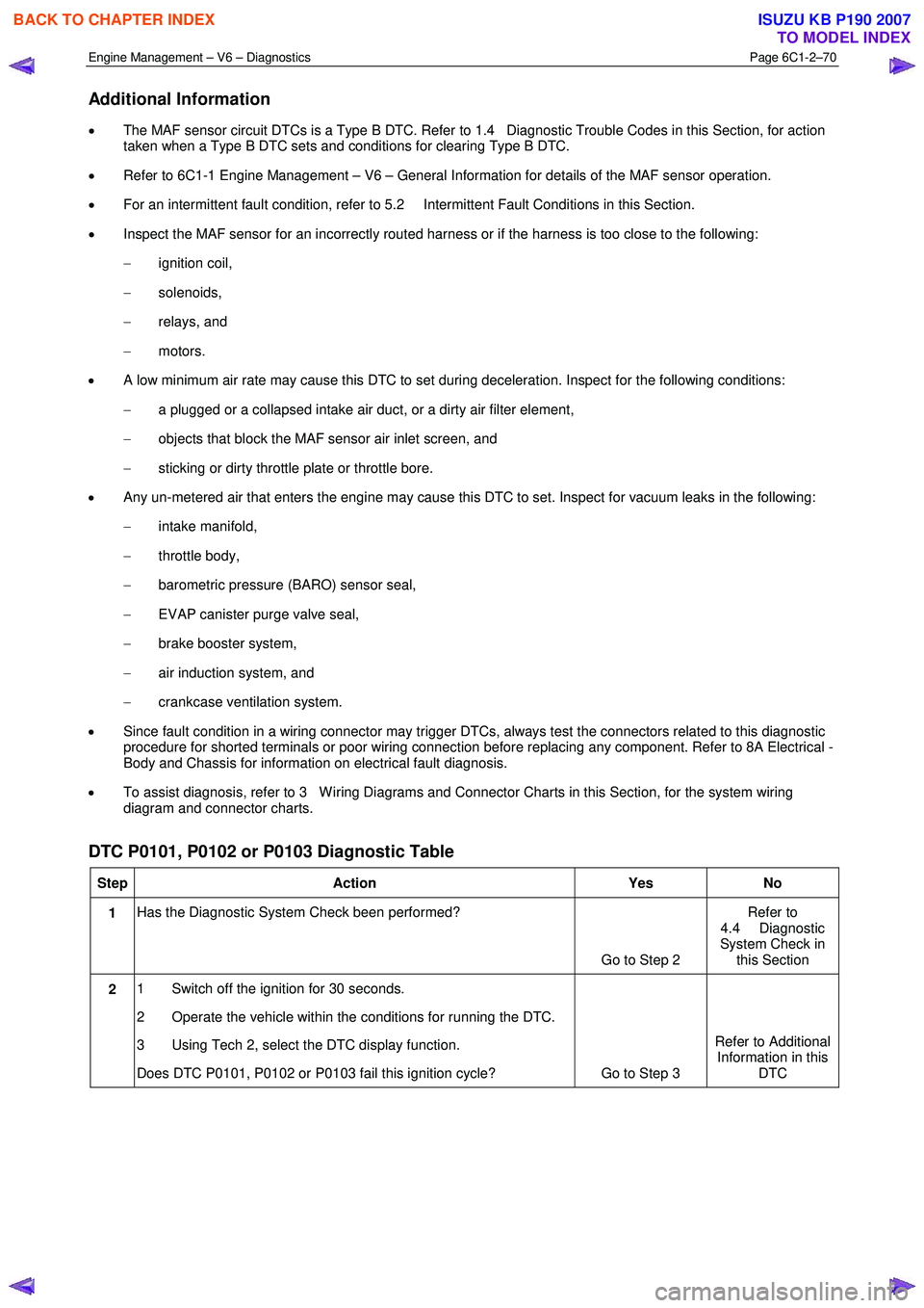
Engine Management – V6 – Diagnostics Page 6C1-2–70
Additional Information
• The MAF sensor circuit DTCs is a Type B DTC. Refer to 1.4 Diagnostic Trouble Codes in this Section, for action
taken when a Type B DTC sets and conditions for clearing Type B DTC.
• Refer to 6C1-1 Engine Management – V6 – General Information for details of the MAF sensor operation.
• For an intermittent fault condition, refer to 5.2 Intermittent Fault Conditions in this Section.
• Inspect the MAF sensor for an incorrectly routed harness or if the harness is too close to the following:
− ignition coil,
− solenoids,
− relays, and
− motors.
• A low minimum air rate may cause this DTC to set during deceleration. Inspect for the following conditions:
− a plugged or a collapsed intake air duct, or a dirty air filter element,
− objects that block the MAF sensor air inlet screen, and
− sticking or dirty throttle plate or throttle bore.
• Any un-metered air that enters the engine may cause this DTC to set. Inspect for vacuum leaks in the following:
− intake manifold,
− throttle body,
− barometric pressure (BARO) sensor seal,
− EVAP canister purge valve seal,
− brake booster system,
− air induction system, and
− crankcase ventilation system.
• Since fault condition in a wiring connector may trigger DTCs, always test the connectors related to this diagnostic
procedure for shorted terminals or poor wiring connection before replacing any component. Refer to 8A Electrical -
Body and Chassis for information on electrical fault diagnosis.
• To assist diagnosis, refer to 3 W iring Diagrams and Connector Charts in this Section, for the system wiring
diagram and connector charts.
DTC P0101, P0102 or P0103 Diagnostic Table
Step Action Yes No
1 Has the Diagnostic System Check been performed?
Go to Step 2 Refer to
4.4 Diagnostic
System Check in this Section
2 1 Switch off the ignition for 30 seconds.
2 Operate the vehicle within the conditions for running the DTC.
3 Using Tech 2, select the DTC display function.
Does DTC P0101, P0102 or P0103 fail this ignition cycle? Go to Step 3 Refer to Additional
Information in this DTC
BACK TO CHAPTER INDEX
TO MODEL INDEX
ISUZU KB P190 2007
Page 3349 of 6020
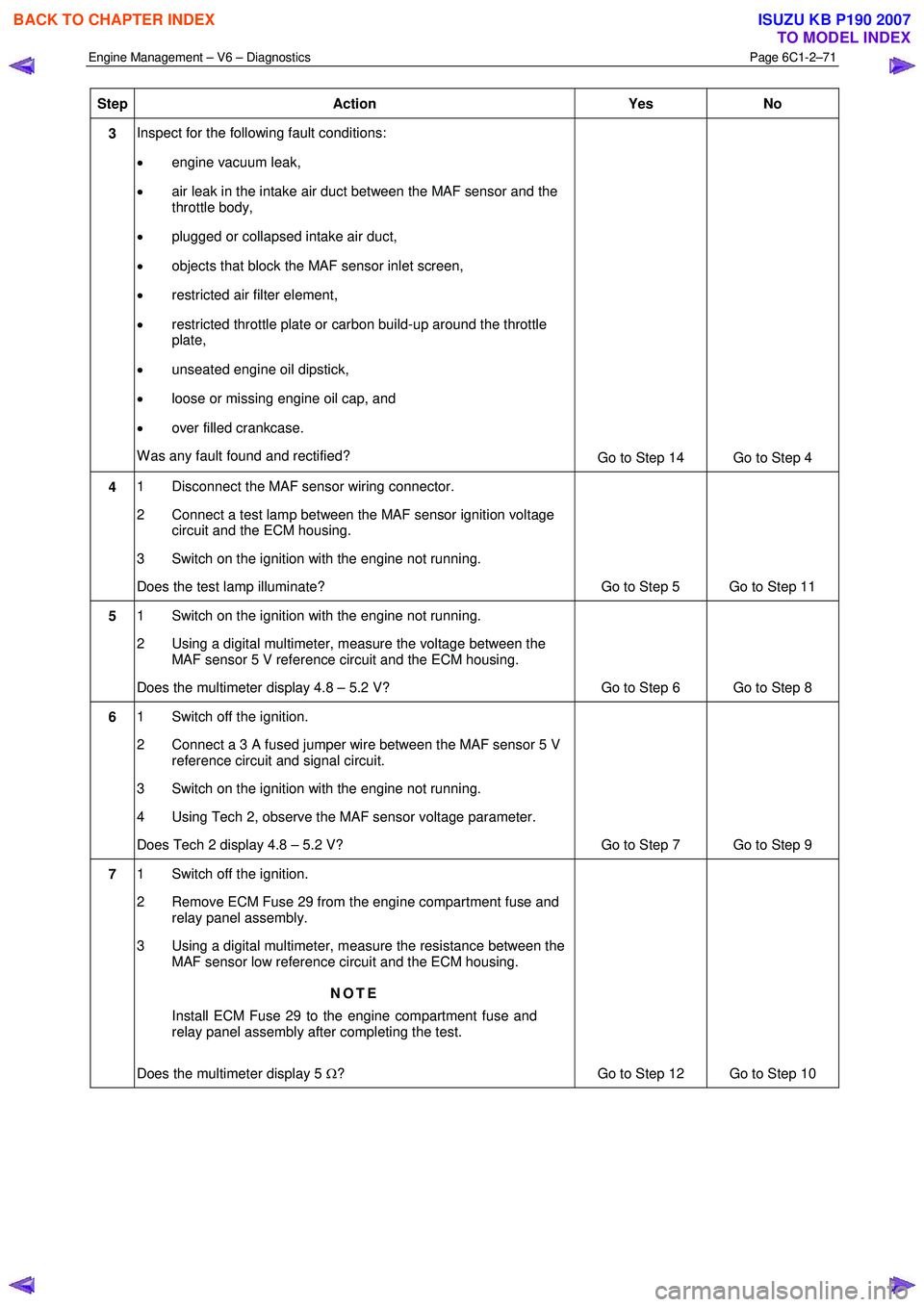
Engine Management – V6 – Diagnostics Page 6C1-2–71
Step Action Yes No
3 Inspect for the following fault conditions:
• engine vacuum leak,
• air leak in the intake air duct between the MAF sensor and the
throttle body,
• plugged or collapsed intake air duct,
• objects that block the MAF sensor inlet screen,
• restricted air filter element,
• restricted throttle plate or carbon build-up around the throttle
plate,
• unseated engine oil dipstick,
• loose or missing engine oil cap, and
• over filled crankcase.
W as any fault found and rectified? Go to Step 14 Go to Step 4
4 1 Disconnect the MAF sensor wiring connector.
2 Connect a test lamp between the MAF sensor ignition voltage circuit and the ECM housing.
3 Switch on the ignition with the engine not running.
Does the test lamp illuminate? Go to Step 5 Go to Step 11
5 1 Switch on the ignition with the engine not running.
2 Using a digital multimeter, measure the voltage between the MAF sensor 5 V reference circuit and the ECM housing.
Does the multimeter display 4.8 – 5.2 V? Go to Step 6 Go to Step 8
6 1 Switch off the ignition.
2 Connect a 3 A fused jumper wire between the MAF sensor 5 V reference circuit and signal circuit.
3 Switch on the ignition with the engine not running.
4 Using Tech 2, observe the MAF sensor voltage parameter.
Does Tech 2 display 4.8 – 5.2 V? Go to Step 7 Go to Step 9
7 1 Switch off the ignition.
2 Remove ECM Fuse 29 from the engine compartment fuse and relay panel assembly.
3 Using a digital multimeter, measure the resistance between the MAF sensor low reference circuit and the ECM housing.
NOTE
Install ECM Fuse 29 to the engine compartment fuse and
relay panel assembly after completing the test.
Does the multimeter display 5 Ω? Go to Step 12 Go to Step 10
BACK TO CHAPTER INDEX
TO MODEL INDEX
ISUZU KB P190 2007
Page 3365 of 6020
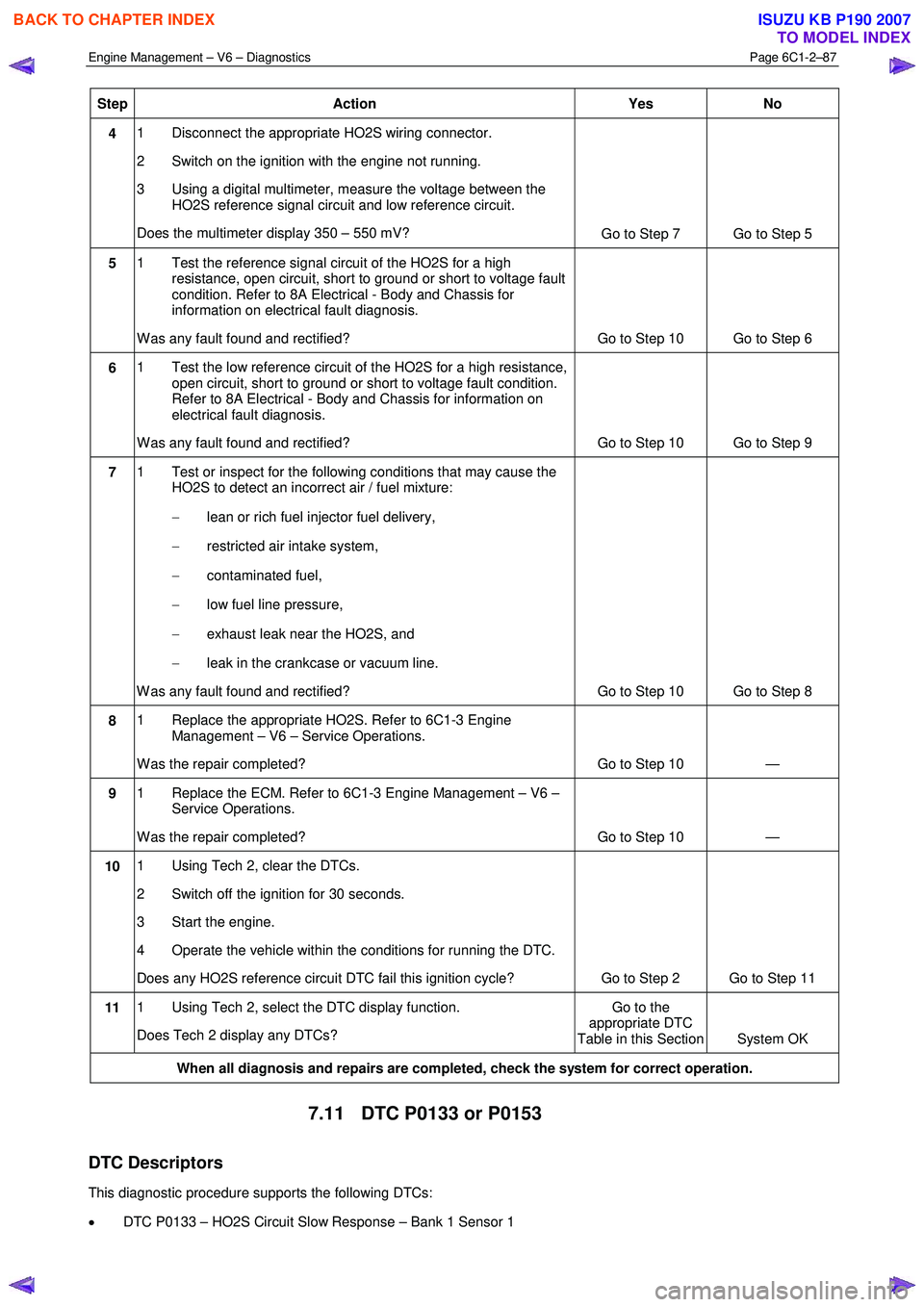
Engine Management – V6 – Diagnostics Page 6C1-2–87
Step Action Yes No
4 1 Disconnect the appropriate HO2S wiring connector.
2 Switch on the ignition with the engine not running.
3 Using a digital multimeter, measure the voltage between the HO2S reference signal circuit and low reference circuit.
Does the multimeter display 350 – 550 mV? Go to Step 7 Go to Step 5
5 1 Test the reference signal circuit of the HO2S for a high
resistance, open circuit, short to ground or short to voltage fault
condition. Refer to 8A Electrical - Body and Chassis for
information on electrical fault diagnosis.
W as any fault found and rectified? Go to Step 10 Go to Step 6
6 1 Test the low reference circuit of the HO2S for a high resistance,
open circuit, short to ground or short to voltage fault condition.
Refer to 8A Electrical - Body and Chassis for information on
electrical fault diagnosis.
W as any fault found and rectified? Go to Step 10 Go to Step 9
7 1 Test or inspect for the following conditions that may cause the
HO2S to detect an incorrect air / fuel mixture:
− lean or rich fuel injector fuel delivery,
− restricted air intake system,
− contaminated fuel,
− low fuel line pressure,
− exhaust leak near the HO2S, and
− leak in the crankcase or vacuum line.
W as any fault found and rectified? Go to Step 10 Go to Step 8
8 1 Replace the appropriate HO2S. Refer to 6C1-3 Engine
Management – V6 – Service Operations.
W as the repair completed? Go to Step 10 —
9 1 Replace the ECM. Refer to 6C1-3 Engine Management – V6 –
Service Operations.
W as the repair completed? Go to Step 10 —
10 1 Using Tech 2, clear the DTCs.
2 Switch off the ignition for 30 seconds.
3 Start the engine.
4 Operate the vehicle within the conditions for running the DTC.
Does any HO2S reference circuit DTC fail this ignition cycle? Go to Step 2 Go to Step 11
11 1 Using Tech 2, select the DTC display function.
Does Tech 2 display any DTCs? Go to the
appropriate DTC
Table in this Section System OK
When all diagnosis and repairs are completed, check the system for correct operation.
7.11 DTC P0133 or P0153
DTC Descriptors
This diagnostic procedure supports the following DTCs:
• DTC P0133 – HO2S Circuit Slow Response – Bank 1 Sensor 1
BACK TO CHAPTER INDEX
TO MODEL INDEX
ISUZU KB P190 2007