2007 ISUZU KB P190 vacuum
[x] Cancel search: vacuumPage 3372 of 6020
Engine Management – V6 – Diagnostics Page 6C1-2–94
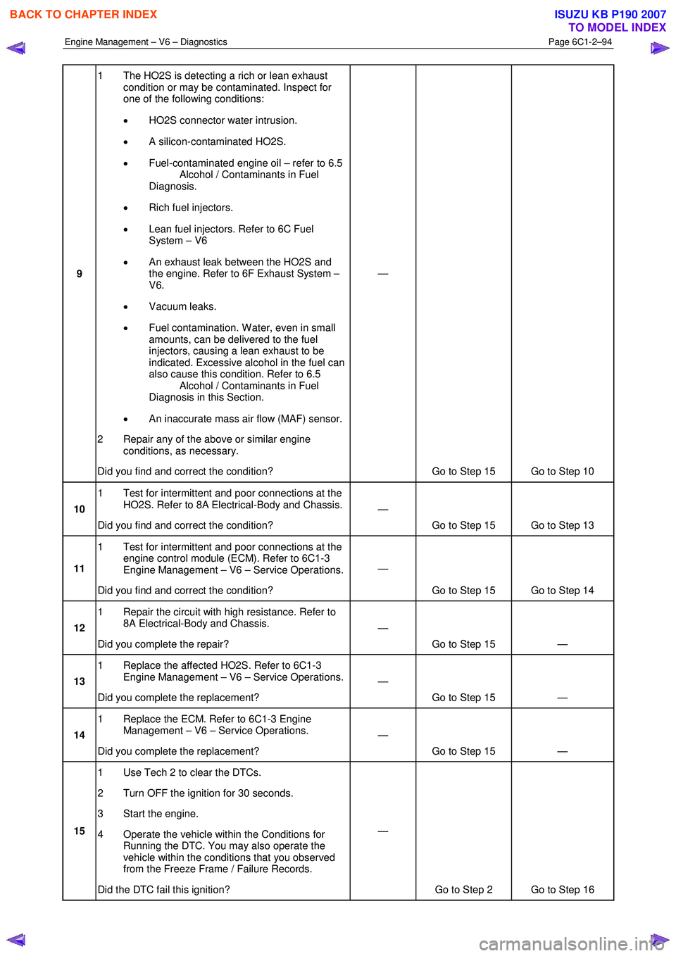
9 1 The HO2S is detecting a rich or lean exhaust
condition or may be contaminated. Inspect for
one of the following conditions:
• HO2S connector water intrusion.
• A silicon-contaminated HO2S.
• Fuel-contaminated engine oil – refer to 6.5
Alcohol / Contaminants in Fuel
Diagnosis.
• Rich fuel injectors.
• Lean fuel injectors. Refer to 6C Fuel
System – V6
• An exhaust leak between the HO2S and
the engine. Refer to 6F Exhaust System –
V6.
• Vacuum leaks.
• Fuel contamination. W ater, even in small
amounts, can be delivered to the fuel
injectors, causing a lean exhaust to be
indicated. Excessive alcohol in the fuel can
also cause this condition. Refer to 6.5
Alcohol / Contaminants in Fuel
Diagnosis in this Section.
• An inaccurate mass air flow (MAF) sensor.
2 Repair any of the above or similar engine conditions, as necessary.
Did you find and correct the condition? —
Go to Step 15 Go to Step 10
10 1 Test for intermittent and poor connections at the
HO2S. Refer to 8A Electrical-Body and Chassis.
Did you find and correct the condition? —
Go to Step 15 Go to Step 13
11 1 Test for intermittent and poor connections at the
engine control module (ECM). Refer to 6C1-3
Engine Management – V6 – Service Operations.
Did you find and correct the condition? —
Go to Step 15 Go to Step 14
12 1 Repair the circuit with high resistance. Refer to
8A Electrical-Body and Chassis.
Did you complete the repair? —
Go to Step 15 —
13 1 Replace the affected HO2S. Refer to 6C1-3
Engine Management – V6 – Service Operations.
Did you complete the replacement? —
Go to Step 15 —
14 1 Replace the ECM. Refer to 6C1-3 Engine
Management – V6 – Service Operations.
Did you complete the replacement? —
Go to Step 15 —
15 1 Use Tech 2 to clear the DTCs.
2 Turn OFF the ignition for 30 seconds.
3 Start the engine.
4 Operate the vehicle within the Conditions for Running the DTC. You may also operate the
vehicle within the conditions that you observed
from the Freeze Frame / Failure Records.
Did the DTC fail this ignition? —
Go to Step 2 Go to Step 16
BACK TO CHAPTER INDEX
TO MODEL INDEX
ISUZU KB P190 2007
Page 3382 of 6020

Engine Management – V6 – Diagnostics Page 6C1-2–104
Step Action Yes No
9 1 Inspect or test for the following conditions:
• Inspect the vacuum hoses for splits, kinks, and proper
connections.
• Inspect the throttle body and the intake manifold for
vacuum leaks.
• Inspect the crankcase ventilation valve and / or system for
any vacuum leaks.
• Test for the correct fuel pressure. Refer to 6C Fuel System
– V6.
• Inspect the fuel system for any restrictions, leaks or fuel
contamination. Refer to 6C Fuel System – V6.
• Inspect for fouled or damaged spark plugs. Determine
what caused the spark plugs to foul. Refer to 6C1-3
Engine Management – Service Operations.
• Inspect the exhaust system for restrictions. Refer to 6F
Exhaust System – V6.
• Inspect the engine control grounds for being clean, tight,
and in the correct location.
• Inspect for a camshaft actuator stuck in the full advance or
retard position.
2 Repair as required.
Did you find and correct the condition? Go to Step 10 Go to Symptoms in
6A1 Engine
Mechanical – V6
10 1 Use Tech 2 to clear the DTCs.
2 Switch off the ignition for 30 seconds.
3 Start the engine.
4 Operate the vehicle within the Conditions for Running DTC 300.
Did the DTC fail this ignition? Go to Step 2 Go to Step 11
11 1 Using Tech 2, select the DTC display function.
Does Tech display any DTCs? Go to the
appropriate DTC
Table in this Section System OK
When all diagnosis and repairs are completed, clear all DTCs and verify correct operation
7.17 DTC P0301, P0302, P0303, P0304, P0305
or P0306
DTC Descriptor
This diagnostic procedure supports the following DTCs:
• DTC P0301 – Cylinder 1 Misfire Detected
• DTC P0302 – Cylinder 2 Misfire Detected
• DTC P0303 – Cylinder 3 Misfire Detected
• DTC P0304 – Cylinder 4 Misfire Detected
• DTC P0305 – Cylinder 5 Misfire Detected
• DTC P0306 – Cylinder 6 Misfire Detected
BACK TO CHAPTER INDEX
TO MODEL INDEX
ISUZU KB P190 2007
Page 3463 of 6020
Engine Management – V6 – Diagnostics Page 6C1-2–185
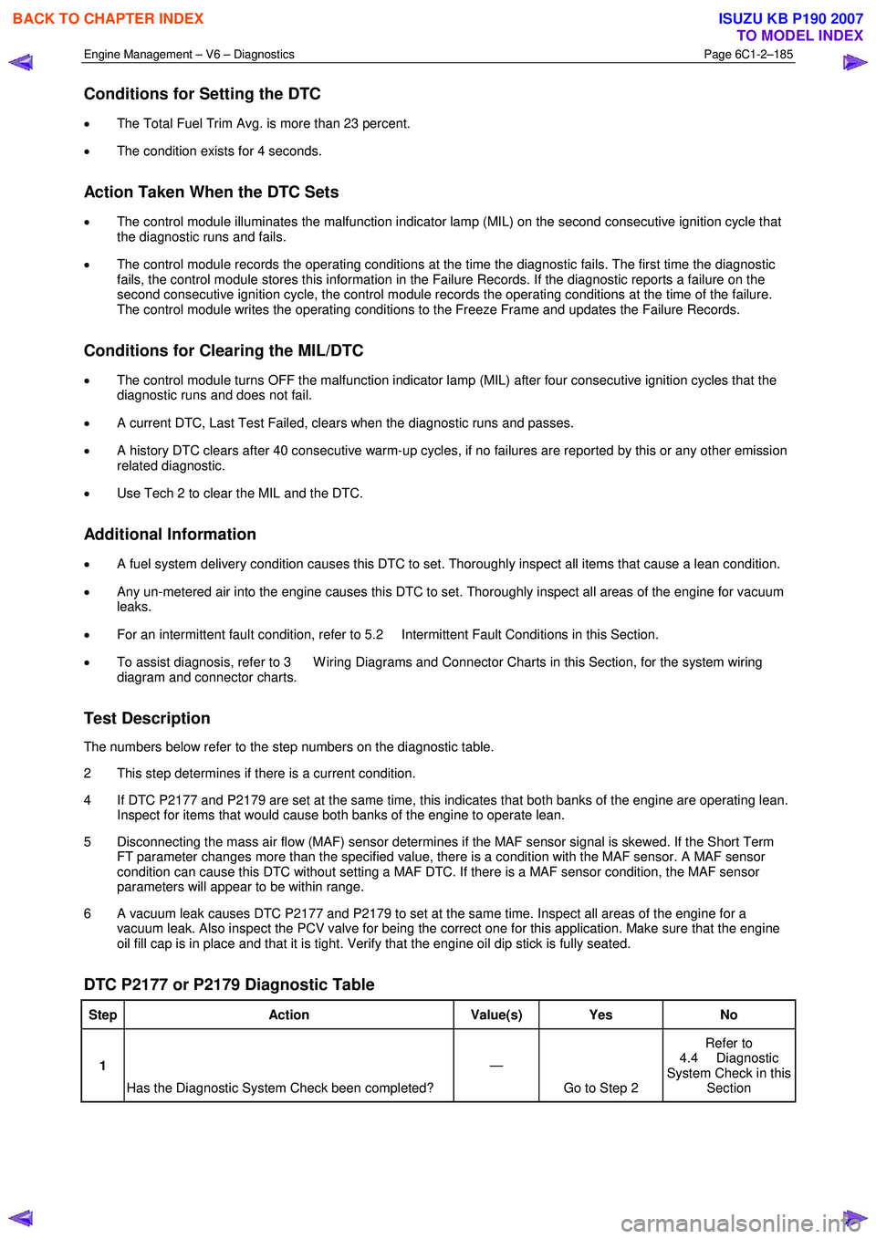
Conditions for Setting the DTC
• The Total Fuel Trim Avg. is more than 23 percent.
• The condition exists for 4 seconds.
Action Taken When the DTC Sets
• The control module illuminates the malfunction indicator lamp (MIL) on the second consecutive ignition cycle that
the diagnostic runs and fails.
• The control module records the operating conditions at the time the diagnostic fails. The first time the diagnostic
fails, the control module stores this information in the Failure Records. If the diagnostic reports a failure on the
second consecutive ignition cycle, the control module records the operating conditions at the time of the failure.
The control module writes the operating conditions to the Freeze Frame and updates the Failure Records.
Conditions for Clearing the MIL/DTC
• The control module turns OFF the malfunction indicator lamp (MIL) after four consecutive ignition cycles that the
diagnostic runs and does not fail.
• A current DTC, Last Test Failed, clears when the diagnostic runs and passes.
• A history DTC clears after 40 consecutive warm-up cycles, if no failures are reported by this or any other emission
related diagnostic.
• Use Tech 2 to clear the MIL and the DTC.
Additional Information
• A fuel system delivery condition causes this DTC to set. Thoroughly inspect all items that cause a lean condition.
• Any un-metered air into the engine causes this DTC to set. Thoroughly inspect all areas of the engine for vacuum
leaks.
• For an intermittent fault condition, refer to 5.2 Intermittent Fault Conditions in this Section.
• To assist diagnosis, refer to 3 W iring Diagrams and Connector Charts in this Section, for the system wiring
diagram and connector charts.
Test Description
The numbers below refer to the step numbers on the diagnostic table.
2 This step determines if there is a current condition.
4 If DTC P2177 and P2179 are set at the same time, this indicates that both banks of the engine are operating lean. Inspect for items that would cause both banks of the engine to operate lean.
5 Disconnecting the mass air flow (MAF) sensor determines if the MAF sensor signal is skewed. If the Short Term FT parameter changes more than the specified value, there is a condition with the MAF sensor. A MAF sensor
condition can cause this DTC without setting a MAF DTC. If there is a MAF sensor condition, the MAF sensor
parameters will appear to be within range.
6 A vacuum leak causes DTC P2177 and P2179 to set at the same time. Inspect all areas of the engine for a vacuum leak. Also inspect the PCV valve for being the correct one for this application. Make sure that the engine
oil fill cap is in place and that it is tight. Verify that the engine oil dip stick is fully seated.
DTC P2177 or P2179 Diagnostic Table
Step Action Value(s) Yes No
1
Has the Diagnostic System Check been completed? —
Go to Step 2 Refer to
4.4 Diagnostic
System Check in this Section
BACK TO CHAPTER INDEX
TO MODEL INDEX
ISUZU KB P190 2007
Page 3465 of 6020
Engine Management – V6 – Diagnostics Page 6C1-2–187
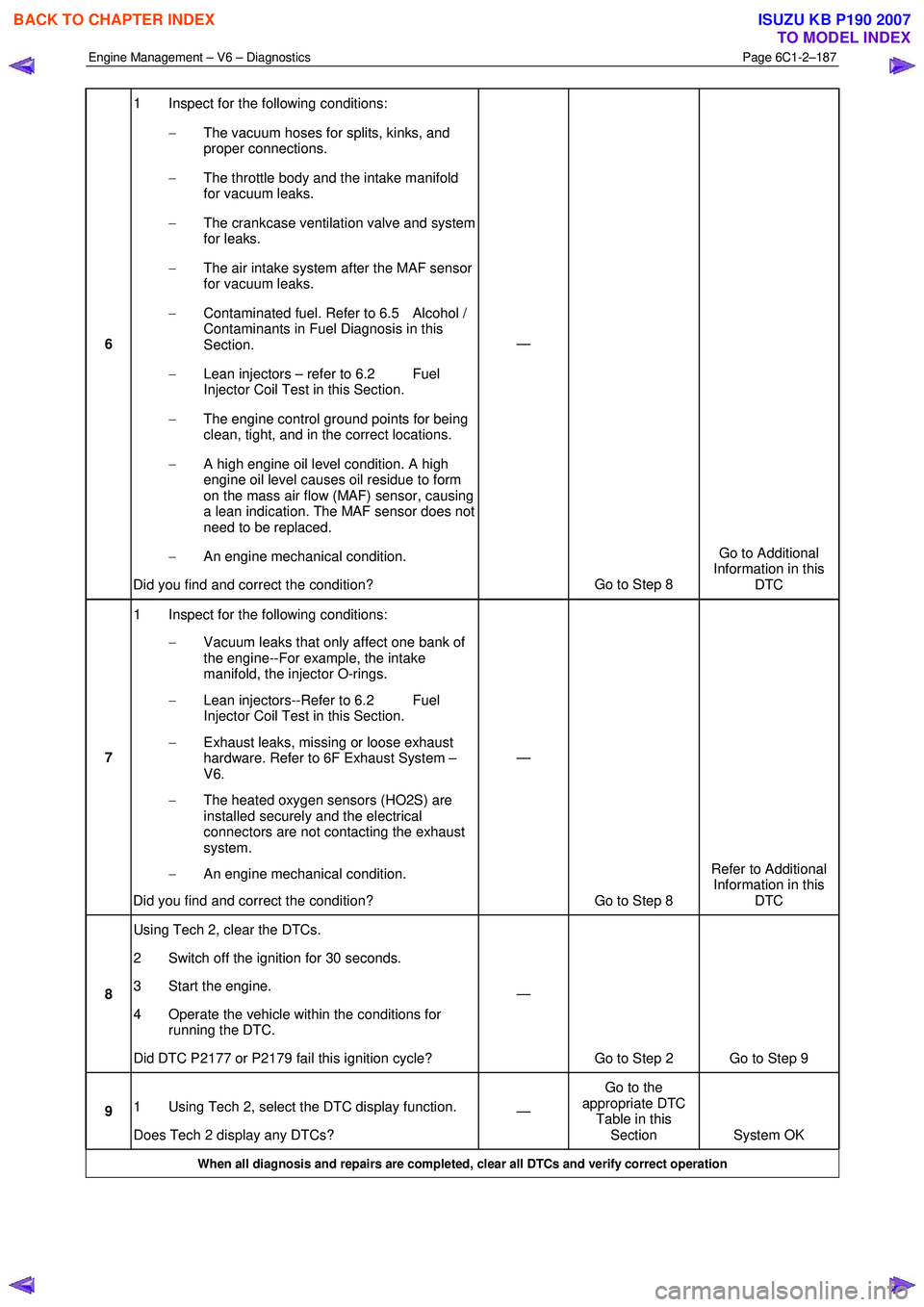
6 1 Inspect for the following conditions:
− The vacuum hoses for splits, kinks, and
proper connections.
− The throttle body and the intake manifold
for vacuum leaks.
− The crankcase ventilation valve and system
for leaks.
− The air intake system after the MAF sensor
for vacuum leaks.
− Contaminated fuel. Refer to 6.5 Alcohol /
Contaminants in Fuel Diagnosis in this
Section.
− Lean injectors – refer to 6.2 Fuel
Injector Coil Test in this Section.
− The engine control ground points for being
clean, tight, and in the correct locations.
− A high engine oil level condition. A high
engine oil level causes oil residue to form
on the mass air flow (MAF) sensor, causing
a lean indication. The MAF sensor does not
need to be replaced.
− An engine mechanical condition.
Did you find and correct the condition? —
Go to Step 8 Go to Additional
Information in this DTC
7 1 Inspect for the following conditions:
− Vacuum leaks that only affect one bank of
the engine--For example, the intake
manifold, the injector O-rings.
− Lean injectors--Refer to 6.2 Fuel
Injector Coil Test in this Section.
− Exhaust leaks, missing or loose exhaust
hardware. Refer to 6F Exhaust System –
V6.
− The heated oxygen sensors (HO2S) are
installed securely and the electrical
connectors are not contacting the exhaust
system.
− An engine mechanical condition.
Did you find and correct the condition? —
Go to Step 8 Refer to Additional
Information in this DTC
8 Using Tech 2, clear the DTCs.
2 Switch off the ignition for 30 seconds.
3 Start the engine.
4 Operate the vehicle within the conditions for running the DTC.
Did DTC P2177 or P2179 fail this ignition cycle? —
Go to Step 2 Go to Step 9
9 1 Using Tech 2, select the DTC display function.
Does Tech 2 display any DTCs? —
Go to the
appropriate DTC Table in this Section System OK
When all diagnosis and repairs are completed, clear all DTCs and verify correct operation
BACK TO CHAPTER INDEX
TO MODEL INDEX
ISUZU KB P190 2007
Page 3470 of 6020
Engine Management – V6 – Diagnostics Page 6C1-2–192
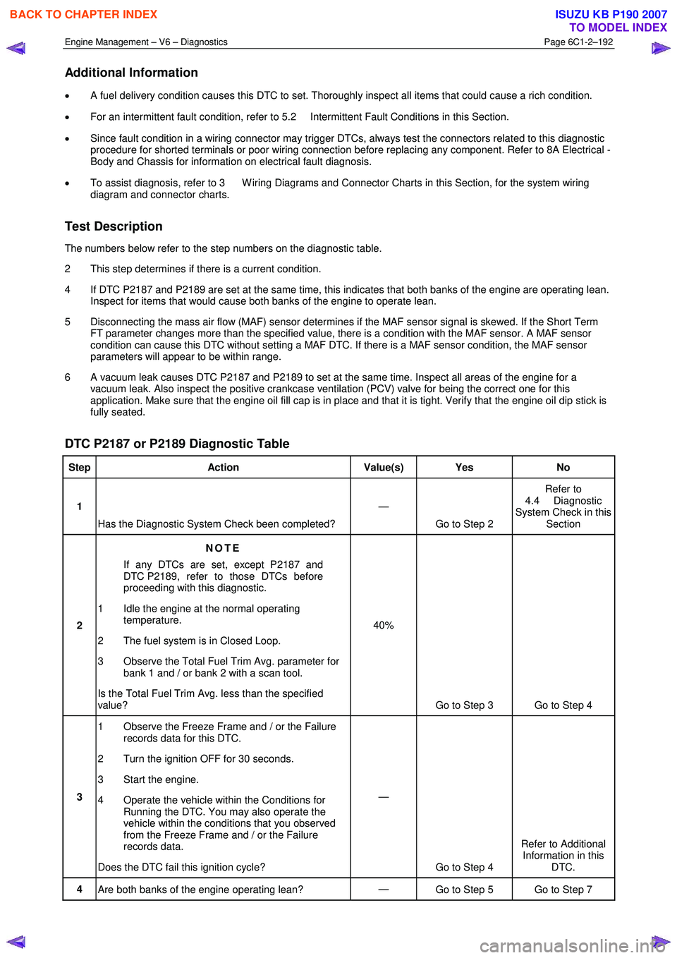
Additional Information
• A fuel delivery condition causes this DTC to set. Thoroughly inspect all items that could cause a rich condition.
• For an intermittent fault condition, refer to 5.2 Intermittent Fault Conditions in this Section.
• Since fault condition in a wiring connector may trigger DTCs, always test the connectors related to this diagnostic
procedure for shorted terminals or poor wiring connection before replacing any component. Refer to 8A Electrical -
Body and Chassis for information on electrical fault diagnosis.
• To assist diagnosis, refer to 3 W iring Diagrams and Connector Charts in this Section, for the system wiring
diagram and connector charts.
Test Description
The numbers below refer to the step numbers on the diagnostic table.
2 This step determines if there is a current condition.
4 If DTC P2187 and P2189 are set at the same time, this indicates that both banks of the engine are operating lean. Inspect for items that would cause both banks of the engine to operate lean.
5 Disconnecting the mass air flow (MAF) sensor determines if the MAF sensor signal is skewed. If the Short Term FT parameter changes more than the specified value, there is a condition with the MAF sensor. A MAF sensor
condition can cause this DTC without setting a MAF DTC. If there is a MAF sensor condition, the MAF sensor
parameters will appear to be within range.
6 A vacuum leak causes DTC P2187 and P2189 to set at the same time. Inspect all areas of the engine for a vacuum leak. Also inspect the positive crankcase ventilation (PCV) valve for being the correct one for this
application. Make sure that the engine oil fill cap is in place and that it is tight. Verify that the engine oil dip stick is
fully seated.
DTC P2187 or P2189 Diagnostic Table
Step Action Value(s) Yes No
1
Has the Diagnostic System Check been completed? —
Go to Step 2 Refer to
4.4 Diagnostic
System Check in this Section
2 NOTE
If any DTCs are set, except P2187 and
DTC P2189, refer to those DTCs before
proceeding with this diagnostic.
1 Idle the engine at the normal operating temperature.
2 The fuel system is in Closed Loop.
3 Observe the Total Fuel Trim Avg. parameter for bank 1 and / or bank 2 with a scan tool.
Is the Total Fuel Trim Avg. less than the specified
value? 40%
Go to Step 3 Go to Step 4
3 1 Observe the Freeze Frame and / or the Failure
records data for this DTC.
2 Turn the ignition OFF for 30 seconds.
3 Start the engine.
4 Operate the vehicle within the Conditions for Running the DTC. You may also operate the
vehicle within the conditions that you observed
from the Freeze Frame and / or the Failure
records data.
Does the DTC fail this ignition cycle? —
Go to Step 4 Refer to Additional
Information in this DTC.
4 Are both banks of the engine operating lean? —
Go to Step 5 Go to Step 7
BACK TO CHAPTER INDEX
TO MODEL INDEX
ISUZU KB P190 2007
Page 3471 of 6020
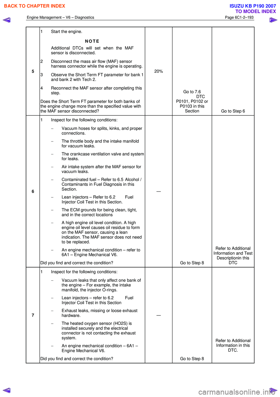
Engine Management – V6 – Diagnostics Page 6C1-2–193
5 1 Start the engine.
NOTE
Additional DTCs will set when the MAF
sensor is disconnected.
2 Disconnect the mass air flow (MAF) sensor harness connector while the engine is operating.
3 Observe the Short Term FT parameter for bank 1 and bank 2 with Tech 2.
4 Reconnect the MAF sensor after completing this step.
Does the Short Term FT parameter for both banks of
the engine change more than the specified value with
the MAF sensor disconnected? 20%
Go to 7.6
DTC
P0101, P0102 or P0103 in this Section Go to Step 6
6 1 Inspect for the following conditions:
− Vacuum hoses for splits, kinks, and proper
connections.
− The throttle body and the intake manifold
for vacuum leaks.
− The crankcase ventilation valve and system
for leaks.
− Air intake system after the MAF sensor for
vacuum leaks.
− Contaminated fuel – Refer to 6.5 Alcohol /
Contaminants in Fuel Diagnosis in this
Section.
− Lean injectors – Refer to 6.2 Fuel
Injector Coil Test in this Section.
− The ECM grounds for being clean, tight,
and in the correct locations
− A high engine oil level condition. A high
engine oil level causes oil residue to form
on the MAF sensor, causing a lean
indication. The MAF sensor does not need
to be replaced.
− An engine mechanical condition – refer to
6A1 – Engine Mechanical V6.
Did you find and correct the condition? —
Go to Step 8 Refer to Additional
Information and Test Descriptionin this DTC
7 1 Inspect for the following conditions:
− Vacuum leaks that only affect one bank of
the engine – For example, the intake
manifold, the injector O-rings.
− Lean injectors – refer to 6.2 Fuel
Injector Coil Test in this Section
− Exhaust leaks, missing or loose exhaust
hardware.
− The heated oxygen sensor (HO2S) is
installed securely and the electrical
connector is not contacting the exhaust
system.
− An engine mechanical condition – 6A1 –
Engine Mechanical V6.
Did you find and correct the condition? —
Go to Step 8 Refer to Additional
Information in this DTC.
BACK TO CHAPTER INDEX
TO MODEL INDEX
ISUZU KB P190 2007
Page 3492 of 6020
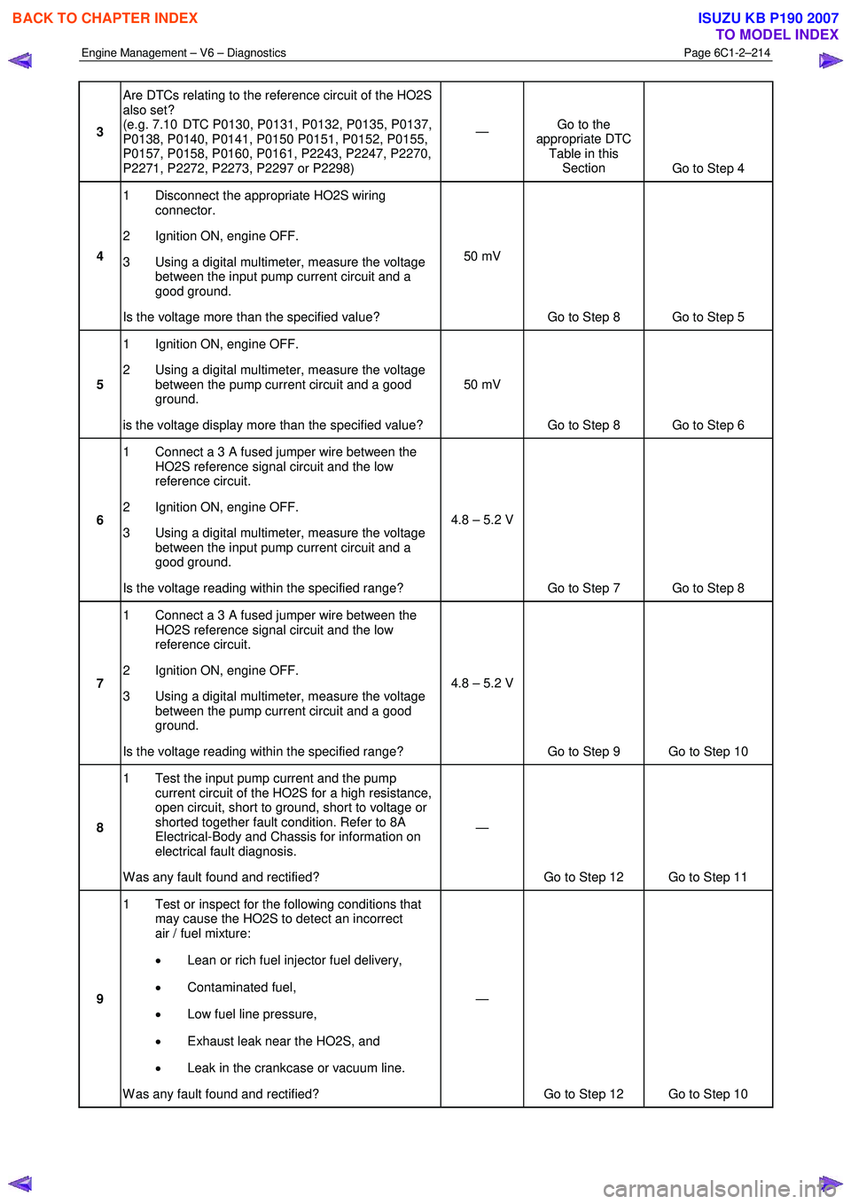
Engine Management – V6 – Diagnostics Page 6C1-2–214
3 Are DTCs relating to the reference circuit of the HO2S
also set?
(e.g. 7.10 DTC P0130, P0131, P0132, P0135, P0137,
P0138, P0140, P0141, P0150 P0151, P0152, P0155,
P0157, P0158, P0160, P0161, P2243, P2247, P2270,
P2271, P2272, P2273, P2297 or P2298) —
Go to the
appropriate DTC Table in this Section Go to Step 4
4 1 Disconnect the appropriate HO2S wiring
connector.
2 Ignition ON, engine OFF.
3 Using a digital multimeter, measure the voltage between the input pump current circuit and a
good ground.
Is the voltage more than the specified value? 50 mV
Go to Step 8 Go to Step 5
5 1 Ignition ON, engine OFF.
2 Using a digital multimeter, measure the voltage between the pump current circuit and a good
ground.
is the voltage display more than the specified value? 50 mV
Go to Step 8 Go to Step 6
6 1 Connect a 3 A fused jumper wire between the
HO2S reference signal circuit and the low
reference circuit.
2 Ignition ON, engine OFF.
3 Using a digital multimeter, measure the voltage between the input pump current circuit and a
good ground.
Is the voltage reading within the specified range? 4.8 – 5.2 V
Go to Step 7 Go to Step 8
7 1 Connect a 3 A fused jumper wire between the
HO2S reference signal circuit and the low
reference circuit.
2 Ignition ON, engine OFF.
3 Using a digital multimeter, measure the voltage between the pump current circuit and a good
ground.
Is the voltage reading within the specified range? 4.8 – 5.2 V
Go to Step 9 Go to Step 10
8 1 Test the input pump current and the pump
current circuit of the HO2S for a high resistance,
open circuit, short to ground, short to voltage or
shorted together fault condition. Refer to 8A
Electrical-Body and Chassis for information on
electrical fault diagnosis.
W as any fault found and rectified? —
Go to Step 12 Go to Step 11
9 1 Test or inspect for the following conditions that
may cause the HO2S to detect an incorrect
air / fuel mixture:
• Lean or rich fuel injector fuel delivery,
• Contaminated fuel,
• Low fuel line pressure,
• Exhaust leak near the HO2S, and
• Leak in the crankcase or vacuum line.
W as any fault found and rectified? —
Go to Step 12 Go to Step 10
BACK TO CHAPTER INDEX
TO MODEL INDEX
ISUZU KB P190 2007
Page 3577 of 6020
Engine Management – V6 – Service Operations Page 6C1-3–53
Reinstall
Reinstallation of the spark plug is the reverse of the removal procedure, noting the following:
• Discard the spark plug if it has been
dropped.
• Do not use anti-seize compound or similar
lubricant on the spark plug threads.
1 Using a suitably sized rubber tube attached to the spark plug terminal post, hand start each spark plug into the cylinder head thread.
Failure to tighten a spark plug to the correct
torque specification may result in premature
spark plug failure, and / or engine damage.
2 Tighten the spark plug/s to the correct torque specification. Spark plug torque specification ...............16.0 – 20.0 Nm
3 Road test the vehicle and check for correct operation.
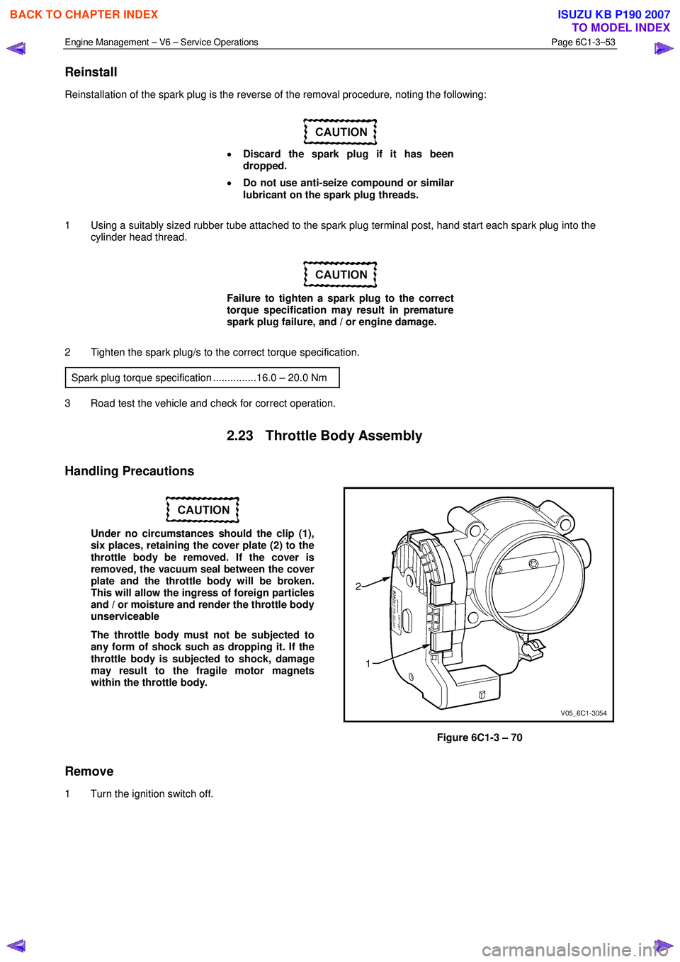
2.23 Throttle Body Assembly
Handling Precautions
Under no circumstances should the clip (1),
six places, retaining the cover plate (2) to the
throttle body be removed. If the cover is
removed, the vacuum seal between the cover
plate and the throttle body will be broken.
This will allow the ingress of foreign particles
and / or moisture and render the throttle body
unserviceable
The throttle body must not be subjected to
any form of shock such as dropping it. If the
throttle body is subjected to shock, damage
may result to the fragile motor magnets
within the throttle body.
Figure 6C1-3 – 70
Remove
1 Turn the ignition switch off.
BACK TO CHAPTER INDEX
TO MODEL INDEX
ISUZU KB P190 2007