2007 ISUZU KB P190 warning
[x] Cancel search: warningPage 3726 of 6020
Powertrain Interface Module – V6 Page 6E1–65
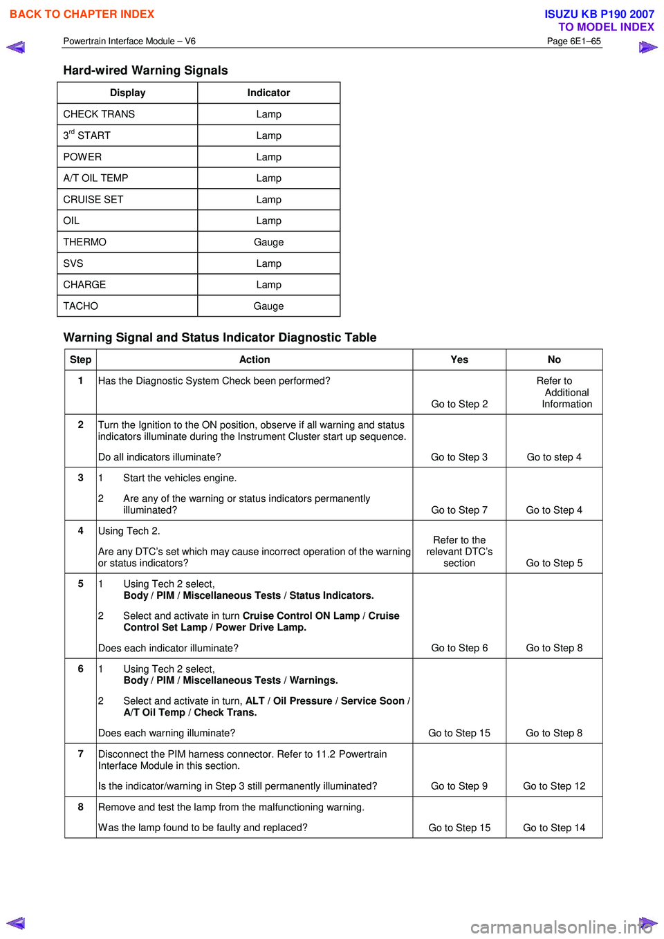
Hard-wired Warning Signals
Display Indicator
CHECK TRANS Lamp
3rd START Lamp
POW ER Lamp
A/T OIL TEMP Lamp
CRUISE SET Lamp
OIL Lamp
THERMO Gauge
SVS Lamp
CHARGE Lamp
TACHO Gauge
Warning Signal and Status Indicator Diagnostic Table
Step Action Yes No
1
Has the Diagnostic System Check been performed?
Go to Step 2 Refer to
Additional
Information
2 Turn the Ignition to the ON position, observe if all warning and status
indicators illuminate during the Instrument Cluster start up sequence.
Do all indicators illuminate? Go to Step 3 Go to step 4
3 1 Start the vehicles engine.
2 Are any of the warning or status indicators permanently illuminated? Go to Step 7 Go to Step 4
4 Using Tech 2.
Are any DTC’s set which may cause incorrect operation of the warning
or status indicators? Refer to the
relevant DTC’s section Go to Step 5
5
1 Using Tech 2 select,
Body / PIM / Miscellaneous Tests / Status Indicators.
2 Select and activate in turn Cruise Control ON Lamp / Cruise
Control Set Lamp / Power Drive Lamp.
Does each indicator illuminate? Go to Step 6 Go to Step 8
6
1 Using Tech 2 select,
Body / PIM / Miscellaneous Tests / Warnings.
2 Select and activate in turn, ALT / Oil Pressure / Service Soon /
A/T Oil Temp / Check Trans.
Does each warning illuminate? Go to Step 15 Go to Step 8
7 Disconnect the PIM harness connector. Refer to 11.2 Powertrain
Interface Module in this section.
Is the indicator/warning in Step 3 still permanently illuminated? Go to Step 9 Go to Step 12
8 Remove and test the lamp from the malfunctioning warning.
W as the lamp found to be faulty and replaced? Go to Step 15 Go to Step 14
BACK TO CHAPTER INDEX
TO MODEL INDEX
ISUZU KB P190 2007
Page 3727 of 6020
Powertrain Interface Module – V6 Page 6E1–66
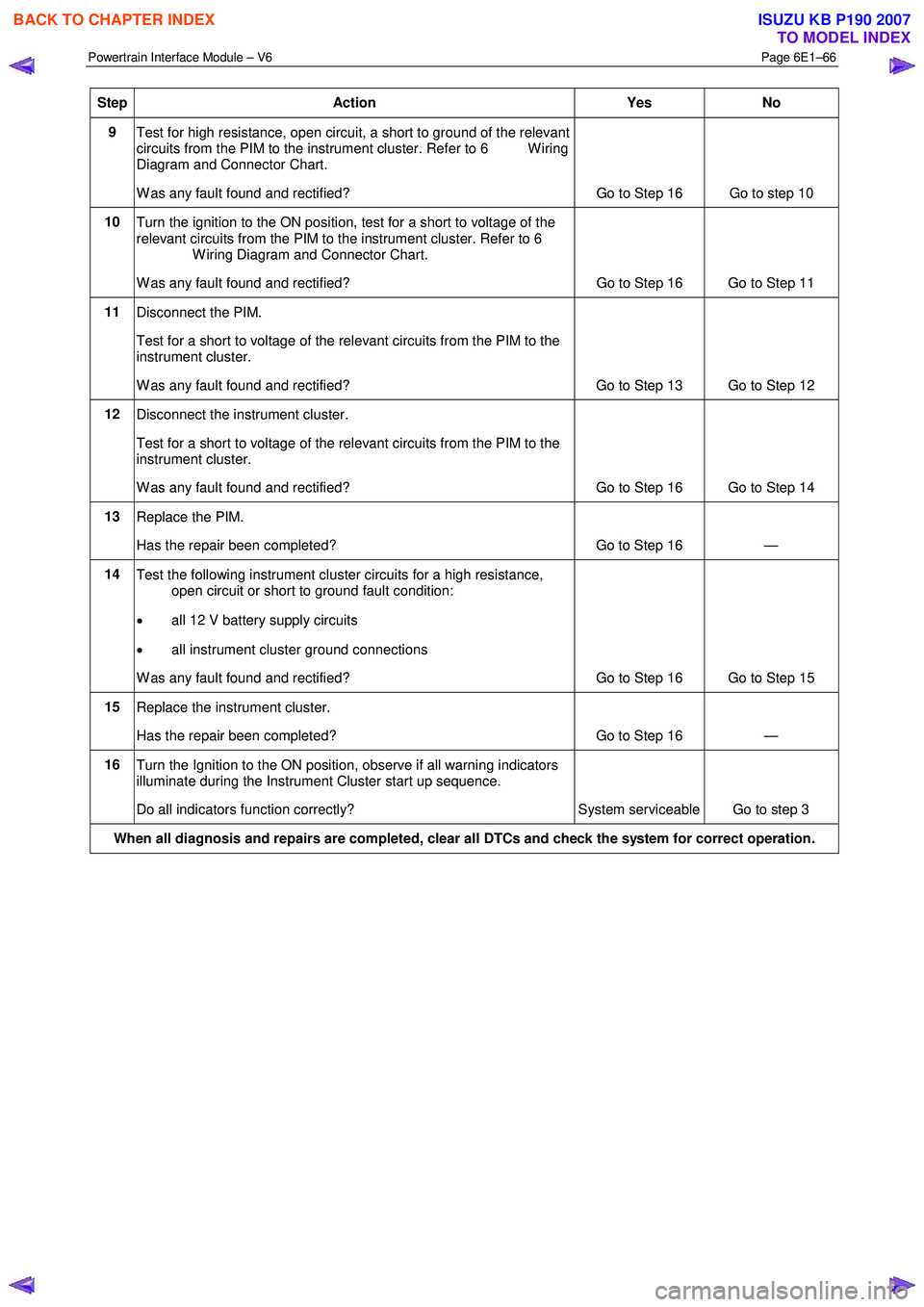
Step Action Yes No
9
Test for high resistance, open circuit, a short to ground of the relevant
circuits from the PIM to the instrument cluster. Refer to 6 W iring
Diagram and Connector Chart.
W as any fault found and rectified? Go to Step 16 Go to step 10
10
Turn the ignition to the ON position, test for a short to voltage of the
relevant circuits from the PIM to the instrument cluster. Refer to 6
W iring Diagram and Connector Chart.
W as any fault found and rectified? Go to Step 16 Go to Step 11
11
Disconnect the PIM.
Test for a short to voltage of the relevant circuits from the PIM to the
instrument cluster.
W as any fault found and rectified? Go to Step 13 Go to Step 12
12 Disconnect the instrument cluster.
Test for a short to voltage of the relevant circuits from the PIM to the
instrument cluster.
W as any fault found and rectified? Go to Step 16 Go to Step 14
13 Replace the PIM.
Has the repair been completed? Go to Step 16 —
14 Test the following instrument cluster circuits for a high resistance,
open circuit or short to ground fault condition:
• all 12 V battery supply circuits
• all instrument cluster ground connections
W as any fault found and rectified? Go to Step 16 Go to Step 15
15 Replace the instrument cluster.
Has the repair been completed? Go to Step 16 —
16 Turn the Ignition to the ON position, observe if all warning indicators
illuminate during the Instrument Cluster start up sequence.
Do all indicators function correctly? System serviceable Go to step 3
When all diagnosis and repairs are completed, clear all DTCs and check the system for correct operation.
BACK TO CHAPTER INDEX
TO MODEL INDEX
ISUZU KB P190 2007
Page 3732 of 6020
Powertrain Interface Module – V6 Page 6E1–71
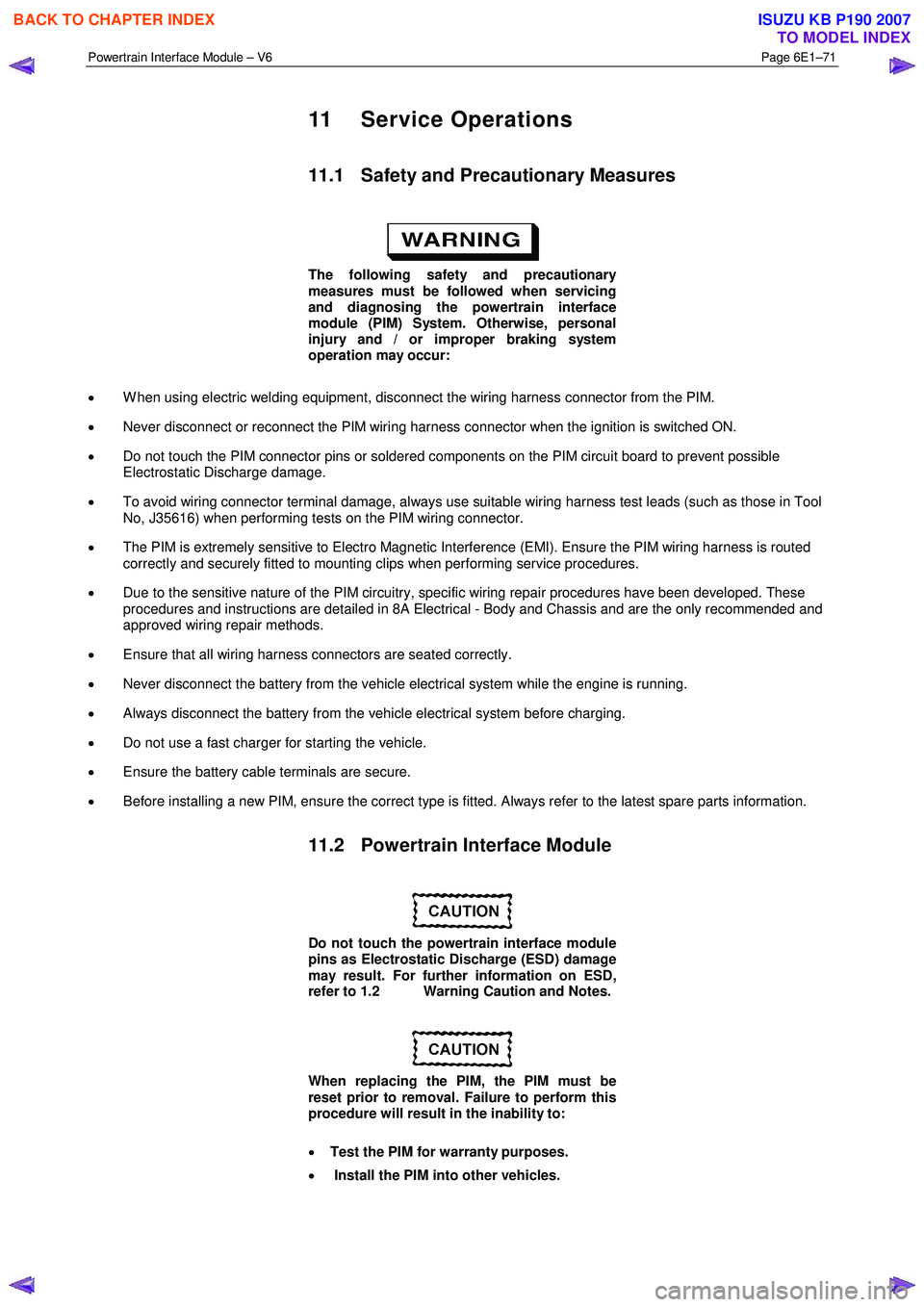
11 Service Operations
11.1 Safety and Precautionary Measures
The following safety and precautionary
measures must be followed when servicing
and diagnosing the powertrain interface
module (PIM) System. Otherwise, personal
injury and / or improper braking system
operation may occur:
• W hen using electric welding equipment, disconnect the wiring harness connector from the PIM.
• Never disconnect or reconnect the PIM wiring harness connector when the ignition is switched ON.
• Do not touch the PIM connector pins or soldered components on the PIM circuit board to prevent possible
Electrostatic Discharge damage.
• To avoid wiring connector terminal damage, always use suitable wiring harness test leads (such as those in Tool
No, J35616) when performing tests on the PIM wiring connector.
• The PIM is extremely sensitive to Electro Magnetic Interference (EMI). Ensure the PIM wiring harness is routed
correctly and securely fitted to mounting clips when performing service procedures.
• Due to the sensitive nature of the PIM circuitry, specific wiring repair procedures have been developed. These
procedures and instructions are detailed in 8A Electrical - Body and Chassis and are the only recommended and
approved wiring repair methods.
• Ensure that all wiring harness connectors are seated correctly.
• Never disconnect the battery from the vehicle electrical system while the engine is running.
• Always disconnect the battery from the vehicle electrical system before charging.
• Do not use a fast charger for starting the vehicle.
• Ensure the battery cable terminals are secure.
• Before installing a new PIM, ensure the correct type is fitted. Always refer to the latest spare parts information.
11.2 Powertrain Interface Module
Do not touch the powertrain interface module
pins as Electrostatic Discharge (ESD) damage
may result. For further information on ESD,
refer to 1.2 Warning Caution and Notes.
When replacing the PIM, the PIM must be
reset prior to removal. Failure to perform this
procedure will result in the inability to:
• Test the PIM for warranty purposes.
• Install the PIM into other vehicles.
BACK TO CHAPTER INDEX
TO MODEL INDEX
ISUZU KB P190 2007
Page 3741 of 6020
Powertrain Interface Module – V6 Page 6E1–80
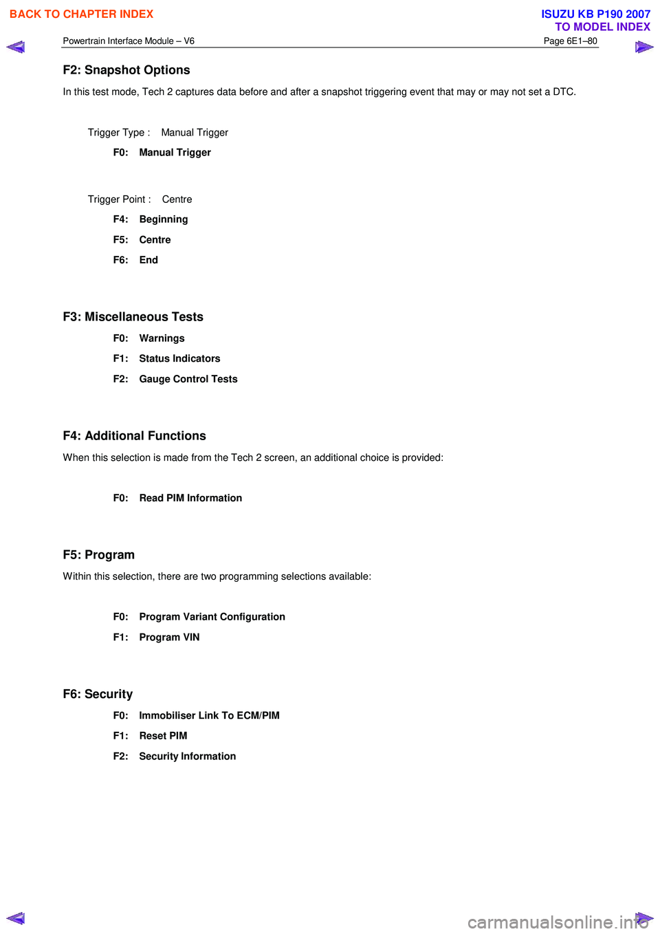
F2: Snapshot Options
In this test mode, Tech 2 captures data before and after a snapshot triggering event that may or may not set a DTC.
Trigger Type : Manual Trigger
F0: Manual Trigger
Trigger Point : Centre
F4: Beginning
F5: Centre
F6: End
F3: Miscellaneous Tests
F0: Warnings
F1: Status Indicators
F2: Gauge Control Tests
F4: Additional Functions
W hen this selection is made from the Tech 2 screen, an additional choice is provided:
F0: Read PIM Information
F5: Program
W ithin this selection, there are two programming selections available:
F0: Program Variant Configuration
F1: Program VIN
F6: Security
F0: Immobiliser Link To ECM/PIM
F1: Reset PIM
F2: Security Information
BACK TO CHAPTER INDEX
TO MODEL INDEX
ISUZU KB P190 2007
Page 3743 of 6020
Powertrain Interface Module – V6 Page 6E1–82
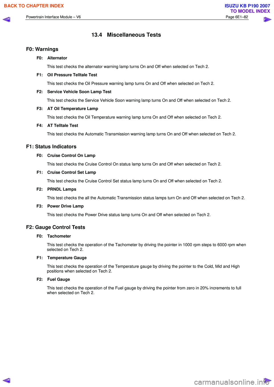
13.4 Miscellaneous Tests
F0: Warnings
F0: Alternator
This test checks the alternator warning lamp turns On and Off when selected on Tech 2.
F1: Oil Pressure Telltale Test
This test checks the Oil Pressure warning lamp turns On and Off when selected on Tech 2.
F2: Service Vehicle Soon Lamp Test
This test checks the Service Vehicle Soon warning lamp turns On and Off when selected on Tech 2.
F3: AT Oil Temperature Lamp
This test checks the Oil Temperature warning lamp turns On and Off when selected on Tech 2.
F4: AT Telltale Test
This test checks the Automatic Transmission warning lamp turns On and Off when selected on Tech 2.
F1: Status Indicators
F0: Cruise Control On Lamp
This test checks the Cruise Control On status lamp turns On and Off when selected on Tech 2.
F1: Cruise Control Set Lamp
This test checks the Cruise Control Set status lamp turns On and Off when selected on Tech 2.
F2: PRNDL Lamps
This test checks the all the Automatic Transmission status lamps turn On and Off when selected on Tech 2.
F3: Power Drive Lamp
This test checks the Power Drive status lamp turns On and Off when selected on Tech 2.
F2: Gauge Control Tests
F0: Tachometer
This test checks the operation of the Tachometer by driving the pointer in 1000 rpm steps to 6000 rpm when
selected on Tech 2.
F1: Temperature Gauge
This test checks the operation of the Temperature gauge by driving the pointer to the Cold, Mid and High
positions when selected on Tech 2.
F2: Fuel Gauge
This test checks the operation of the Fuel gauge by driving the pointer from zero in 20% increments to full when selected on Tech 2.
BACK TO CHAPTER INDEX
TO MODEL INDEX
ISUZU KB P190 2007
Page 3749 of 6020
Exhaust System – V6 Page 6F – 1
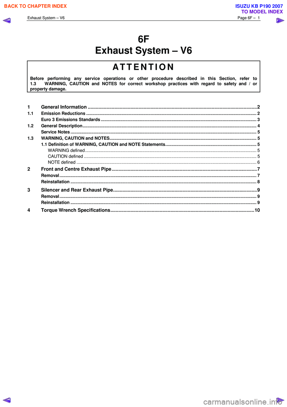
6F
Exhaust System – V6
ATTENTION
Before performing any service operations or other procedure described in this Section, refer to
1.3 WARNING, CAUTION and NOTES for correct workshop practices with regard to safety and / or
property damage.
1 General Information ............................................................................................................ ...................2
1.1 Emission Reductions ............................................................................................................................................ 2
Euro 3 Emissions Standards ................................................................................................................................ 3
1.2 General Description ............................................................................................................ ................................... 4
Service Notes ......................................................................................................................................................... 5
1.3 WARNING, CAUTION and NOTES..................................................................................................... .................... 5
1.1 Definition of WARNING, CAUTION and NOTE Statements......................................................................... .. 5
W ARNING defined ............................................................................................................................................. 5
CAUTION defined .............................................................................................................................................. 5
NOTE defined .................................................................................................................................................... 6
2 Front and Centre Exhaust Pipe .................................................................................................. ...........7
Removal .................................................................................................................................................................. 7
Reinstallation ......................................................................................................................................................... 8
3 Silencer and Rear Exhaust Pipe............................................................................................................9
Removal .................................................................................................................................................................. 9
Reinstallation ......................................................................................................................................................... 9
4 Torque Wrench Specifications............................................................................................................10
BACK TO CHAPTER INDEX
TO MODEL INDEX
ISUZU KB P190 2007
Page 3753 of 6020
Exhaust System – V6 Page 6F – 5
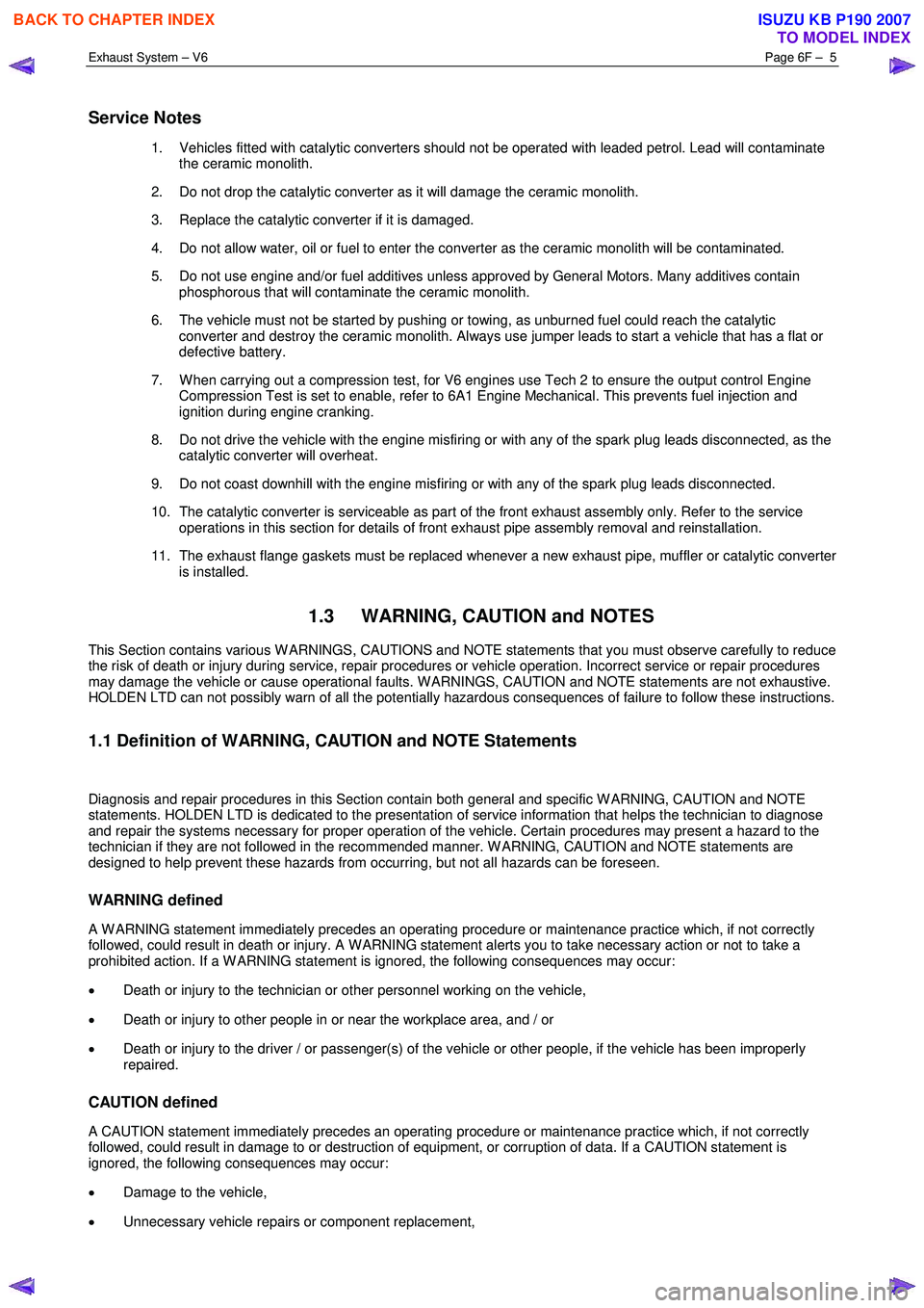
Service Notes
1. Vehicles fitted with catalytic converters should not be operated with leaded petrol. Lead will contaminate
the ceramic monolith.
2. Do not drop the catalytic converter as it will damage the ceramic monolith.
3. Replace the catalytic converter if it is damaged.
4. Do not allow water, oil or fuel to enter the converter as the ceramic monolith will be contaminated.
5. Do not use engine and/or fuel additives unless approved by General Motors. Many additives contain phosphorous that will contaminate the ceramic monolith.
6. The vehicle must not be started by pushing or towing, as unburned fuel could reach the catalytic converter and destroy the ceramic monolith. Always use jumper leads to start a vehicle that has a flat or
defective battery.
7. W hen carrying out a compression test, for V6 engines use Tech 2 to ensure the output control Engine Compression Test is set to enable, refer to 6A1 Engine Mechanical. This prevents fuel injection and
ignition during engine cranking.
8. Do not drive the vehicle with the engine misfiring or with any of the spark plug leads disconnected, as the catalytic converter will overheat.
9. Do not coast downhill with the engine misfiring or with any of the spark plug leads disconnected.
10. The catalytic converter is serviceable as part of the front exhaust assembly only. Refer to the service operations in this section for details of front exhaust pipe assembly removal and reinstallation.
11. The exhaust flange gaskets must be replaced whenever a new exhaust pipe, muffler or catalytic converter is installed.
1.3 WARNING, CAUTION and NOTES
This Section contains various W ARNINGS, CAUTIONS and NOTE statements that you must observe carefully to reduce
the risk of death or injury during service, repair procedures or vehicle operation. Incorrect service or repair procedures
may damage the vehicle or cause operational faults. W ARNINGS, CAUTION and NOTE statements are not exhaustive.
HOLDEN LTD can not possibly warn of all the potentially hazardous consequences of failure to follow these instructions.
1.1 Definition of WARNING, CAUTION and NOTE Statements
Diagnosis and repair procedures in this Section contain both general and specific W ARNING, CAUTION and NOTE
statements. HOLDEN LTD is dedicated to the presentation of service information that helps the technician to diagnose
and repair the systems necessary for proper operation of the vehicle. Certain procedures may present a hazard to the
technician if they are not followed in the recommended manner. W ARNING, CAUTION and NOTE statements are
designed to help prevent these hazards from occurring, but not all hazards can be foreseen.
WARNING defined
A W ARNING statement immediately precedes an operating procedure or maintenance practice which, if not correctly
followed, could result in death or injury. A W ARNING statement alerts you to take necessary action or not to take a
prohibited action. If a W ARNING statement is ignored, the following consequences may occur:
• Death or injury to the technician or other personnel working on the vehicle,
• Death or injury to other people in or near the workplace area, and / or
• Death or injury to the driver / or passenger(s) of the vehicle or other people, if the vehicle has been improperly
repaired.
CAUTION defined
A CAUTION statement immediately precedes an operating procedure or maintenance practice which, if not correctly
followed, could result in damage to or destruction of equipment, or corruption of data. If a CAUTION statement is
ignored, the following consequences may occur:
• Damage to the vehicle,
• Unnecessary vehicle repairs or component replacement,
BACK TO CHAPTER INDEX
TO MODEL INDEX
ISUZU KB P190 2007
Page 3761 of 6020
Automatic Transmission – 4L60E – General Information Page 7C1–1
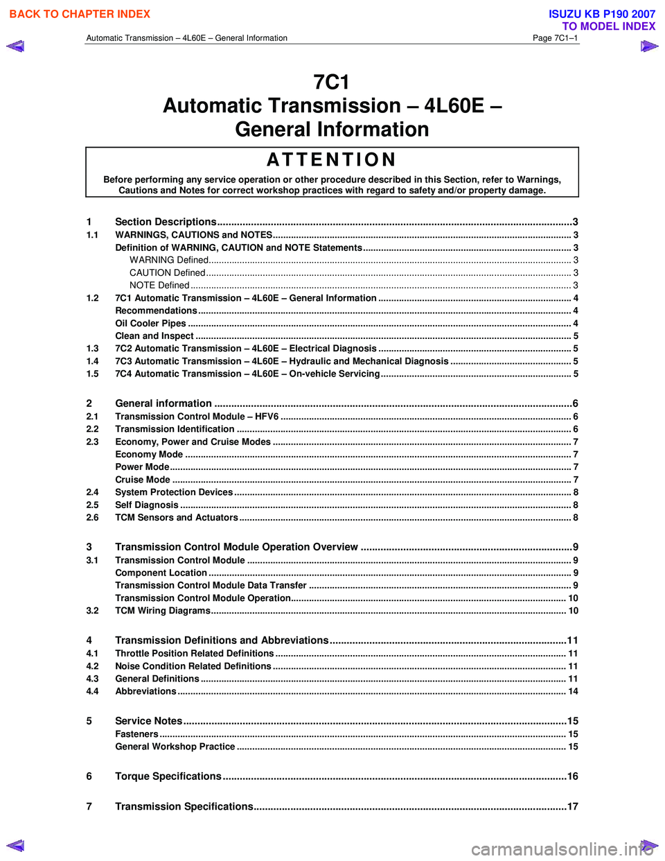
7C1
Automatic Transmission – 4L60E –
General Information
ATTENTION
Before performing any service operation or other procedure described in this Section, refer to Warnings, Cautions and Notes for correct workshop practices with regard to safety and/or property damage.
1 Section Descriptions ........................................................................................................... ...................3
1.1 WARNINGS, CAUTIONS and NOTES................................................................................................... ................. 3
Definition of WARNING, CAUTION and NOTE Statements ............................................................................. .... 3
WARNING Defined............................................................................................................................................. 3
CAUTION Defined .............................................................................................................................................. 3
NOTE Defined .................................................................................................................................................... 3
1.2 7C1 Automatic Transmission – 4L60E – General Information ....................................................................... .... 4
Recommendations ................................................................................................................................................. 4
Oil Cooler Pipes ..................................................................................................................................................... 4
Clean and Inspect .............................................................................................................. .................................... 5
1.3 7C2 Automatic Transmission – 4L60E – Electrical Diagnosis ...................................................................... ..... 5
1.4 7C3 Automatic Transmission – 4L60E – Hydraulic and Mechanical Diagnosis ............................................... 5
1.5 7C4 Automatic Transmission – 4L60E – On-vehicle Servicing ...................................................................... .... 5
2 General information ...............................................................................................................................6
2.1 Transmission Control Module – HFV6 ............................................................................................. .................... 6
2.2 Transmission Identification .................................................................................................................................. 6
2.3 Economy, Power and Cruise Modes .................................................................................................................... 7
Economy Mode ...................................................................................................................................................... 7
Power Mode ............................................................................................................................................................ 7
Cruise Mode ........................................................................................................................................................... 7
2.4 System Protection Devices ...................................................................................................... ............................. 8
2.5 Self Diagnosis ........................................................................................................................................................ 8
2.6 TCM Sensors and Actuators ................................................................................................................................. 8
3 Transmission Control Module Operation Overview ...........................................................................9
3.1 Transmission Control Module .............................................................................................................................. 9
Component Location ............................................................................................................. ................................ 9
Transmission Control Module Data Transfer ...................................................................................... ................ 9
Transmission Control Module Operation........................................................................................................... 10
3.2 TCM Wiring Diagrams.......................................................................................................................................... 10
4 Transmission Definitions and Abbreviations ....................................................................................1 1
4.1 Throttle Position Related Definitions ................................................................................................................. 11
4.2 Noise Condition Related Definitions ............................................................................................ ...................... 11
4.3 General Definitions .............................................................................................................................................. 11
4.4 Abbreviations ....................................................................................................................................................... 14
5 Service Notes ........................................................................................................................................15
Fasteners .............................................................................................................................................................. 15
General Workshop Practice ................................................................................................................................ 15
6 Torque Specifications .......................................................................................................... ................16
7 Transmission Specifications.................................................................................................... ...........17
BACK TO CHAPTER INDEX
TO MODEL INDEX
ISUZU KB P190 2007