2007 ISUZU KB P190 warning
[x] Cancel search: warningPage 3588 of 6020
Charging System – V6 Page 6D1-1-1
6D1-1
Charging System – V6
ATTENTION
Before performing any service operations or other procedure described in this Section, refer to
1.2 WARNING, CAUTION and NOTES for correct workshop practices with regard to safety and / or
property damage.
1 General Information ............................................................................................................ ...................3
1.1 Components ........................................................................................................................................................... 3
Generator................................................................................................................................................................ 3
Generator Types ................................................................................................................................................ 3
Voltage Regulator .................................................................................................................................................. 4
1.2 WARNING, CAUTION and NOTES..................................................................................................... .................... 4
Definition of WARNING, CAUTION and NOTE Statements............................................................................. .... 4
W ARNING defined ............................................................................................................................................. 4
CAUTION defined .............................................................................................................................................. 5
NOTE defined .................................................................................................................................................... 5
1.3 System Operation .................................................................................................................................................. 5
Operation ........................................................................................................................................................... 5
Alternator W arning ............................................................................................................. ................................ 6
2 Diagnosis ................................................................................................................................................7
2.1 Diagnostic General Information ........................................................................................................................... 7
Basic Diagnostic Tools Required ................................................................................................ ......................... 7
2.2 Tech 2 Data List ..................................................................................................................................................... 7
2.3 Diagnostic Systems Check ....................................................................................................... ............................ 7
2.4 Wiring Diagram ...................................................................................................................................................... 8
2.5 Charging System Inoperative / Malfunctioning ................................................................................................... 9
Diagnostic Table Notes ......................................................................................................... ............................. 9
Diagnostic Table 120A Generator ................................................................................................ ...................... 9
3 Minor Service Operations ....................................................................................................................10
3.1 Safety Precautions............................................................................................................................................... 10
3.2 Maintenance ......................................................................................................................................................... 10
Regular Checks................................................................................................................. ................................... 10
Lubrication ....................................................................................................................................................... 10
3.3 On-vehicle Testing ............................................................................................................. .................................. 11
Generator On-vehicle Checks.................................................................................................... ......................... 11
Prerequisites .................................................................................................................................................... 11
Generator Test ................................................................................................................................................. 11
Charging Circuit Voltage Drop Test ............................................................................................. ...................... 13
Prerequisites .................................................................................................................................................... 13
Voltage Drop Test ............................................................................................................................................ 13
4 Major Service Operations ....................................................................................................................15
4.1 Generator.............................................................................................................................................................. 15
Remove ................................................................................................................................................................. 15
Reinstall ................................................................................................................................................................ 16
4.2 Generator Mounting Bracket ..................................................................................................... ......................... 17
Remove ................................................................................................................................................................. 17
Reinstall ................................................................................................................................................................ 17
BACK TO CHAPTER INDEX
TO MODEL INDEX
ISUZU KB P190 2007
Page 3591 of 6020
Charging System – V6 Page 6D1-1-4
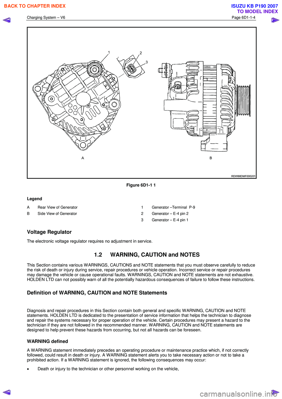
Figure 6D1-1 1
Legend
A Rear View of Generator
B Side View of Generator
1 Generator –Terminal P-9
2 Generator – E-4 pin 2
3 Generator – E-4 pin 1
Voltage Regulator
The electronic voltage regulator requires no adjustment in service.
1.2 WARNING, CAUTION and NOTES
This Section contains various W ARNINGS, CAUTIONS and NOTE statements that you must observe carefully to reduce
the risk of death or injury during service, repair procedures or vehicle operation. Incorrect service or repair procedures
may damage the vehicle or cause operational faults. W ARNINGS, CAUTION and NOTE statements are not exhaustive.
HOLDEN LTD can not possibly warn of all the potentially hazardous consequences of failure to follow these instructions.
Definition of WARNING, CAUTION and NOTE Statements
Diagnosis and repair procedures in this Section contain both general and specific W ARNING, CAUTION and NOTE
statements. HOLDEN LTD is dedicated to the presentation of service information that helps the technician to diagnose
and repair the systems necessary for proper operation of the vehicle. Certain procedures may present a hazard to the
technician if they are not followed in the recommended manner. W ARNING, CAUTION and NOTE statements are
designed to help prevent these hazards from occurring, but not all hazards can be foreseen.
WARNING defined
A W ARNING statement immediately precedes an operating procedure or maintenance practice which, if not correctly
followed, could result in death or injury. A W ARNING statement alerts you to take necessary action or not to take a
prohibited action. If a W ARNING statement is ignored, the following consequences may occur:
• Death or injury to the technician or other personnel working on the vehicle,
BACK TO CHAPTER INDEX
TO MODEL INDEX
ISUZU KB P190 2007
Page 3593 of 6020
Charging System – V6 Page 6D1-1-6
Alternator Warning
NOTE
All generator faults are displayed as
Check Alternator W arning on the instrument
cluster MFD, refer to 8A Electrical Body and
Chassis.
The ECM monitors the voltage on connector E-60 pin 21 and pin 43.
The voltage at the generator connector E-4 pin 2 will remain low when a fault condition is detected in the generator or
associated external circuits. The voltage remains low (while the ignition switch is on) until the fault is repaired.
NOTE
For more information on the alternator warning
refer to 8A Electrical Body and Chassis.
Fault conditions include the following:
• open circuit or excessive voltage drop in circuit 1,
• open circuit in the generator phase connection,
• overcharging conditions,
• short circuit in the regulator output stage,
• open circuit in the rotor winding,
• poor contact between the rectifier and the regulator, and / or
• high resistance in the fusible link assembly.
BACK TO CHAPTER INDEX
TO MODEL INDEX
ISUZU KB P190 2007
Page 3598 of 6020
Charging System – V6 Page 6D1-1-11
3.3 On-vehicle Testing
Generator On-vehicle Checks
Prerequisites
Before testing the generator output, ensure that:
• all generator circuit connections are clean and tight,
• the generator is always connected to the battery during testing (to prevent damage to the diodes),
• the battery is fully charged, and
• the specific gravity does not vary more than 0.025 between cells. (It is recommended the average specific gravity
is 1.260 or higher). Refer to 6D1-3 Battery – V6.
Carry out a load test on the battery to determine its ability to supply and accept current. This is a good indicator of the
general condition of the battery. For details of battery testing, refer to 6D1-3 Battery – V6.
Inspect the drive belt and tensioner markings to determine if the drive belt is within operating limits. Replace the belt if it
is excessively worn or outside the operating range of the tensioner.
For further details, refer to 6A1 Engine Mechanical – V6.
Generator Test
Regulating Voltage Test
NOTE
Leave the generator E-4 wiring harness
connector connected, as it provides initial field
excitation.
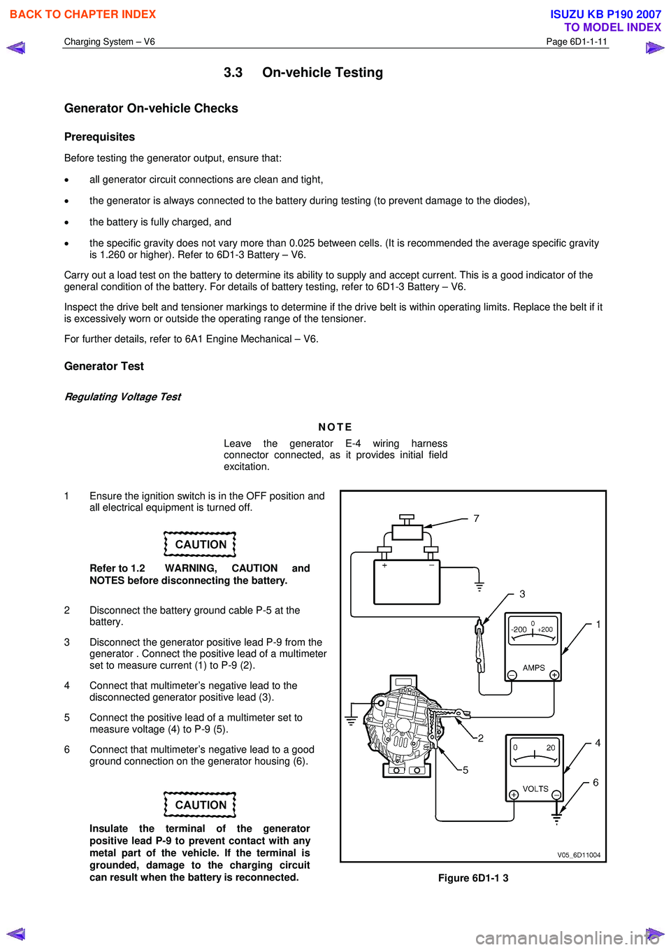
1 Ensure the ignition switch is in the OFF position and all electrical equipment is turned off.
Refer to 1.2 WARNING, CAUTION and
NOTES before disconnecting the battery.
2 Disconnect the battery ground cable P-5 at the battery.
3 Disconnect the generator positive lead P-9 from the generator . Connect the positive lead of a multimeter
set to measure current (1) to P-9 (2).
4 Connect that multimeter’s negative lead to the disconnected generator positive lead (3).
5 Connect the positive lead of a multimeter set to measure voltage (4) to P-9 (5).
6 Connect that multimeter’s negative lead to a good ground connection on the generator housing (6).
Insulate the terminal of the generator
positive lead P-9 to prevent contact with any
metal part of the vehicle. If the terminal is
grounded, damage to the charging circuit
can result when the battery is reconnected.
Figure 6D1-1 3
BACK TO CHAPTER INDEX
TO MODEL INDEX
ISUZU KB P190 2007
Page 3602 of 6020

Charging System – V6 Page 6D1-1-15
4 Major Service Operations
4.1 Generator
Remove
Refer to 1.2 WARNING, CAUTION and NOTES
before disconnecting the battery.
1 Disconnect the battery ground lead P-5. Refer to 8A Electrical Body and Chassis.
2 Insert a ½ inch drive socket bar into the tensioner arm and rotate the tensioner arm clockwise.
3 Remove the drive belt from the generator pulley and release the tensioner. Refer to 6A1 Engine Mechanical – V6 for further details as required.
4 Pull the battery harness cap back from generator terminal P-9 (3), remove the nut (4) and remove the
positive lead (2) from the generator (5).
5 Disengage the connector retaining clip and remove the connector E-4, (1) from the generator.
Figure 6D1-1 4
6 Remove the three bolts (1, 2, 4) retaining the generator (3) to the generator bracket.
7 Remove the generator assembly from the vehicle.
Figure 6D1-1 5
BACK TO CHAPTER INDEX
TO MODEL INDEX
ISUZU KB P190 2007
Page 3603 of 6020
Charging System – V6 Page 6D1-1-16
Reinstall
Reinstallation of the generator is the reverse of the removal procedure, noting the following:
1 Tighten all fasteners to the correct torque specification.
2 Reconnect the battery ground lead.
3 Start the engine.
4 Check the generator warning indicator operation.
5 Check the drive belt is correctly routed and aligned.
6 Check the generator output. Refer to 3.3 On-vehicle Testing.
7 Check the voltage regulator operation. Refer to 3.3 On-vehicle Testing.
8 Turn the ignition switch off.
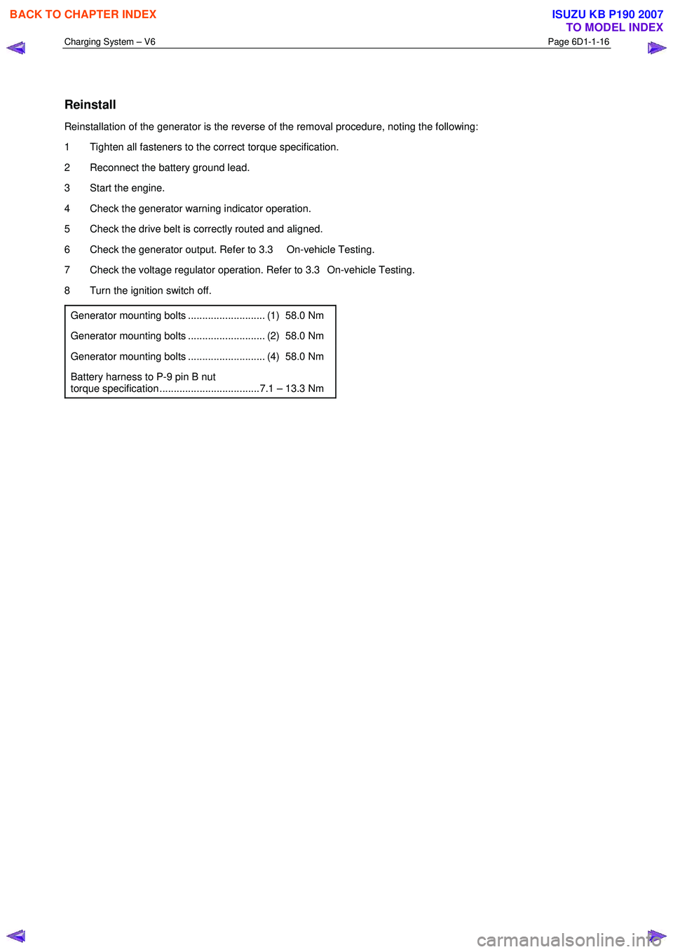
Generator mounting bolts ........................... (1) 58.0 Nm
Generator mounting bolts ........................... (2) 58.0 Nm
Generator mounting bolts ........................... (4) 58.0 Nm
Battery harness to P-9 pin B nut
torque specification ...................................7.1 – 13.3 Nm
BACK TO CHAPTER INDEX
TO MODEL INDEX
ISUZU KB P190 2007
Page 3609 of 6020
Starting System – V6 Page 6D1-2–1
6D1-2
Starting System – V6
ATTENTION
Before performing any service operation or other procedure described in this Section, refer to 1.1
WARNING, CAUTION and NOTES for correct workshop practices with regard to safety and/or property
damage.
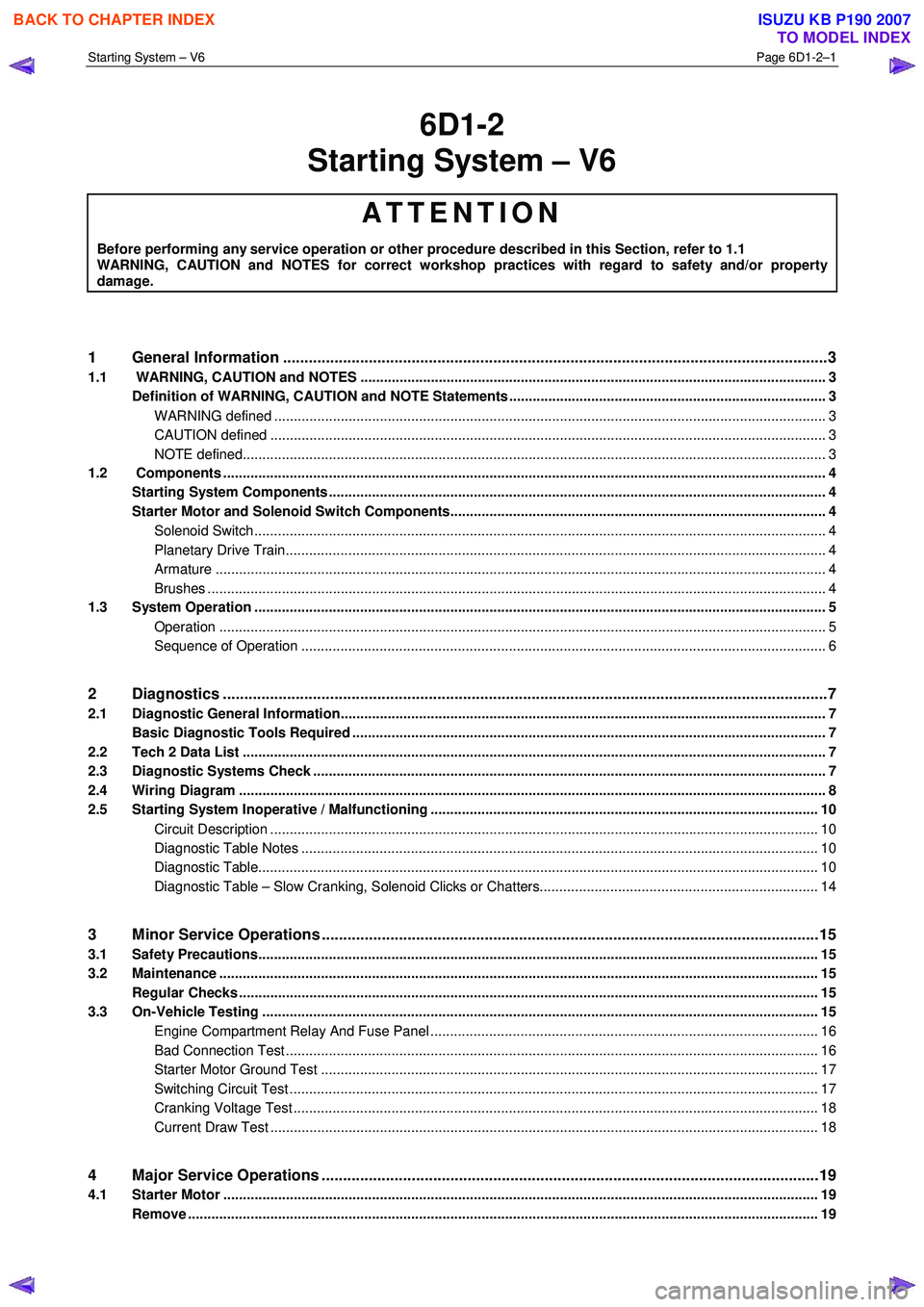
1 General Information ............................................................................................................ ...................3
1.1 WARNING, CAUTION and NOTES .................................................................................................... ................... 3
Definition of WARNING, CAUTION and NOTE Statements ............................................................................. .... 3
WARNING defined ............................................................................................................................................. 3
CAUTION defined .............................................................................................................................................. 3
NOTE defined..................................................................................................................................................... 3
1.2 Components .......................................................................................................................................................... 4
Starting System Components ............................................................................................................................... 4
Starter Motor and Solenoid Switch Components................................................................................... ............. 4
Solenoid Switch.................................................................................................................................................. 4
Planetary Drive Train.......................................................................................................... ................................ 4
Armature ............................................................................................................................................................ 4
Brushes .............................................................................................................................................................. 4
1.3 System Operation .................................................................................................................................................. 5
Operation ...................................................................................................................... ..................................... 5
Sequence of Operation .......................................................................................................... ............................ 6
2 Diagnostics .............................................................................................................................................7
2.1 Diagnostic General Information............................................................................................................................ 7
Basic Diagnostic Tools Required ......................................................................................................................... 7
2.2 Tech 2 Data List ............................................................................................................... ...................................... 7
2.3 Diagnostic Systems Check ....................................................................................................... ............................ 7
2.4 Wiring Diagram ...................................................................................................................................................... 8
2.5 Starting System Inoperative / Malfunctioning ................................................................................... ................ 10
Circuit Description ............................................................................................................................................ 10
Diagnostic Table Notes ......................................................................................................... ........................... 10
Diagnostic Table............................................................................................................................................... 10
Diagnostic Table – Slow Cranking, Solenoid Clicks or Chatters.................................................................. ..... 14
3 Minor Service Operations ....................................................................................................................15
3.1 Safety Precautions............................................................................................................................................... 15
3.2 Maintenance ......................................................................................................................................................... 15
Regular Checks ................................................................................................................. ................................... 15
3.3 On-Vehicle Testing ............................................................................................................. ................................. 15
Engine Compartment Relay And Fuse Panel ........................................................................................ ........... 16
Bad Connection Test ........................................................................................................................................ 16
Starter Motor Ground Test ...................................................................................................... ......................... 17
Switching Circuit Test ....................................................................................................................................... 17
Cranking Voltage Test .......................................................................................................... ............................ 18
Current Draw Test ............................................................................................................................................ 18
4 Major Service Operations ....................................................................................................................19
4.1 Starter Motor ........................................................................................................................................................ 19
Remove ................................................................................................................................................................. 19
BACK TO CHAPTER INDEX
TO MODEL INDEX
ISUZU KB P190 2007
Page 3611 of 6020
Starting System – V6 Page 6D1-2–3
1 General Information
All HFV6 engines are fitted with a Mitsubishi starter motor. This consists of a solenoid switch on a DC motor. The motor
has permanent magnet excitation, which has the advantage of low weight a with high output torque and is visually
identifiable by the absence of pole-shoe retaining screws.
The starter motor does not have field coil windings or pole shoes. These parts have been replaced by six permanent
magnets that are held in the pole housing by clips. The positive brushes are now part of the brush plate assembly.
The solenoid switch is the only component of the starter motor assembly that is serviced separately. If any other parts
require replacement, the starter motor must be replaced.
1.1 WARNING, CAUTION and NOTES
This Section contains various W ARNINGS, CAUTIONS and NOTE statements that you must observe carefully to reduce
the risk of death or injury during service, repair procedures or vehicle operation. Incorrect service or repair procedures
may damage the vehicle or cause operational faults. W ARNINGS, CAUTION and NOTE statements are not exhaustive.
HOLDEN LTD can not possibly warn of all the potentially hazardous consequences of failure to follow these instructions.
Definition of WARNING, CAUTION and NOTE Statements
Diagnosis and repair procedures in this Section contain both general and specific W ARNING, CAUTION and NOTE
statements. HOLDEN LTD is dedicated to the presentation of service information that helps the technician to diagnose
and repair the systems necessary for proper operation of the vehicle. Certain procedures may present a hazard to the
technician if they are not followed in the recommended manner. W ARNING, CAUTION and NOTE statements are
designed to help prevent these hazards from occurring, but not all hazards can be foreseen.
WARNING defined
A W ARNING statement immediately precedes an operating procedure or maintenance practice which, if not correctly
followed, could result in death or injury. A W ARNING statement alerts you to take necessary action or not to take a
prohibited action. If a W ARNING statement is ignored, the following consequences may occur:
• Death or injury to the technician or other personnel working on the vehicle,
• Death or injury to other people in or near the workplace area, and / or
• Death or injury to the driver / or passenger(s) of the vehicle or other people, if the vehicle has been improperly
repaired.
CAUTION defined
A CAUTION statement immediately precedes an operating procedure or maintenance practice which, if not correctly
followed, could result in damage to or destruction of equipment, or corruption of data. If a CAUTION statement is ignored,
the following consequences may occur:
• Damage to the vehicle,
• Unnecessary vehicle repairs or component replacement,
• Faulty operation or performance of any system or component being repaired,
• Damage to any system or components which depend on the proper operation of the system or component being
repaired,
• Faulty operation or performance of any systems or components which depend on the proper operation or
performance of the system or component under repair,
• Damage to fasteners, basic tools or special tools and / or
• Leakage of coolant, lubricant or other vital fluids.
NOTE defined
A NOTE statement immediately precedes or follows an operating procedure, maintenance practice or condition that
requires highlighting. A NOTE statement also emphasises necessary characteristics of a diagnostic or repair procedure.
A NOTE statement is designed to:
BACK TO CHAPTER INDEX
TO MODEL INDEX
ISUZU KB P190 2007