2007 ISUZU KB P190 warning
[x] Cancel search: warningPage 3267 of 6020
Engine Management – V6 – General Information Page 6C1-1–25
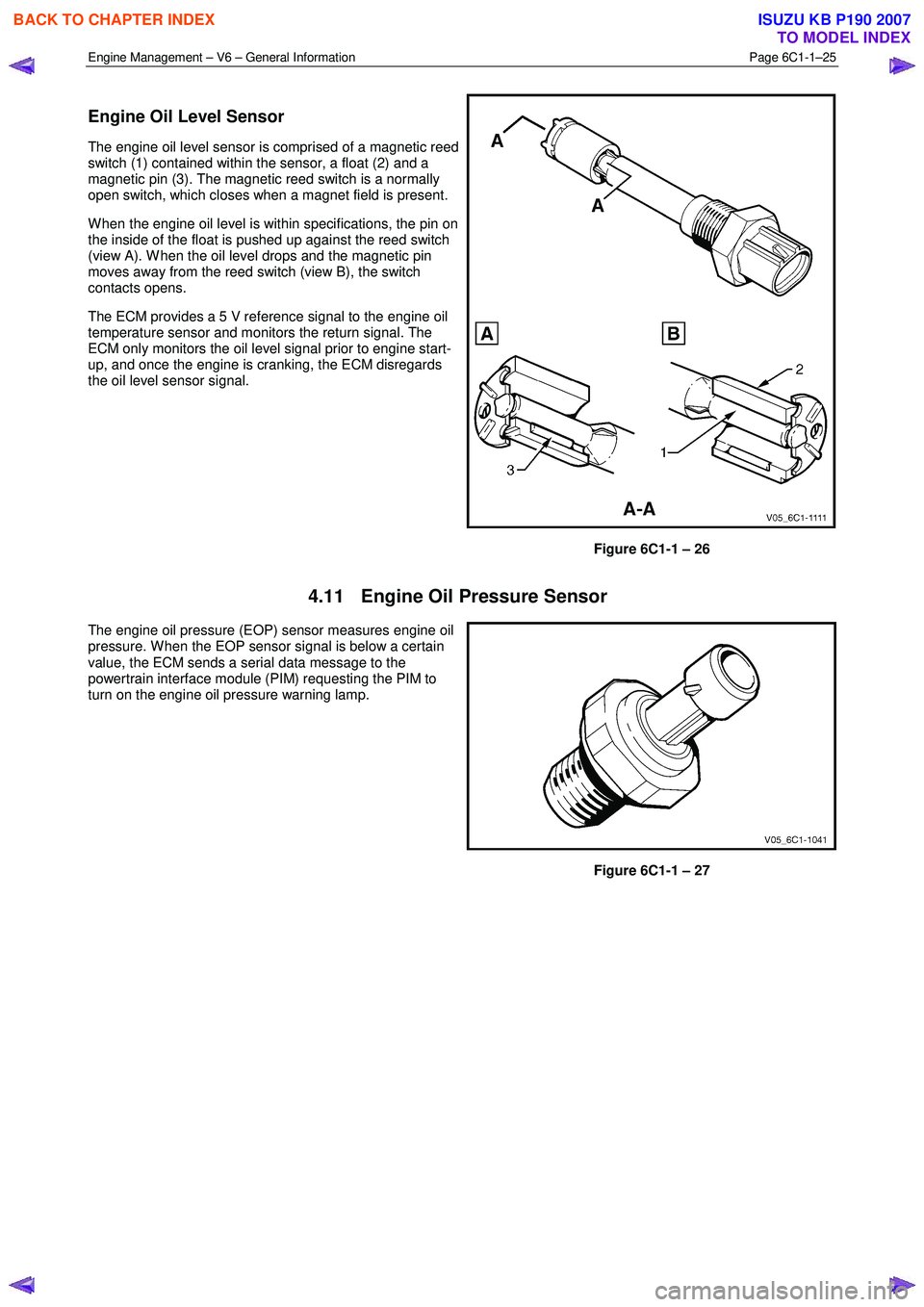
Engine Oil Level Sensor
The engine oil level sensor is comprised of a magnetic reed
switch (1) contained within the sensor, a float (2) and a
magnetic pin (3). The magnetic reed switch is a normally
open switch, which closes when a magnet field is present.
W hen the engine oil level is within specifications, the pin on
the inside of the float is pushed up against the reed switch
(view A). W hen the oil level drops and the magnetic pin
moves away from the reed switch (view B), the switch
contacts opens.
The ECM provides a 5 V reference signal to the engine oil
temperature sensor and monitors the return signal. The
ECM only monitors the oil level signal prior to engine start-
up, and once the engine is cranking, the ECM disregards
the oil level sensor signal.
Figure 6C1-1 – 26
4.11 Engine Oil Pressure Sensor
The engine oil pressure (EOP) sensor measures engine oil
pressure. W hen the EOP sensor signal is below a certain
value, the ECM sends a serial data message to the
powertrain interface module (PIM) requesting the PIM to
turn on the engine oil pressure warning lamp.
Figure 6C1-1 – 27
BACK TO CHAPTER INDEX
TO MODEL INDEX
ISUZU KB P190 2007
Page 3279 of 6020
Engine Management – V6 – Diagnostics Page 6C1-2–1
6C1-2 Engine Management – V6
Diagnostics
ATTENTION
Before performing any service operation or other procedure described in this Section, refer to 1.5 Warning
Caution and Notes for correct workshop practices with regard to safety and/or property damage.
1 General Information ............................................................................................................ ...................4
1.1 Diagnostic System Check ..................................................................................................................................... 4
1.2 Diagnostic Trouble Code Tables ................................................................................................. ......................... 4
1.3 Symptoms Diagnostics ......................................................................................................................................... 5
1.4 Diagnostic Trouble Codes .................................................................................................................................... 5
1.5 Warning Caution and Notes .................................................................................................................................. 6
2 GM LAN Serial Communication Circuit ............................................................................................ ....8
3 Wiring Diagrams and Connector Charts ........................................................................................... ...9
3.1 Wiring Diagrams .................................................................................................................................................... 9
3.2 ECM Connector End Views ................................................................................................................................. 12
3.2 Engine Control Connector End Views ............................................................................................. .................. 16
4 Diagnostics Starting Point...................................................................................................................18
4.1 Basic Requirements ............................................................................................................................................ 18
4.2 Diagnostic Precautions ......................................................................................................... .............................. 18
4.3 Preliminary Checks.............................................................................................................................................. 19
4.4 Diagnostic System Check ........................................................................................................ ........................... 20
5 Symptoms Diagnostics ........................................................................................................................22
5.1 Symptoms Diagnosis Table ....................................................................................................... ......................... 22
5.2 Intermittent Fault Conditions .............................................................................................................................. 22
5.3 Backfire................................................................................................................................................................. 24
5.4 Cranks But Does Not Run ........................................................................................................ ........................... 26
5.5 Cuts Out, Misses.................................................................................................................................................. 27
5.6 Detonation / Spark Knock ....................................................................................................... ............................ 28
5.7 Dieseling, Run-on ................................................................................................................................................ 28
5.8 Hard Start ............................................................................................................................................................. 29
5.9 Hesitation, Sag and Stumble .................................................................................................... .......................... 30
5.10 Lack of Power, Sluggishness or Sponginess ...................................................................................... ............. 31
5.11 Poor Fuel Economy ............................................................................................................................................. 32
5.12 Rough, Unstable, Incorrect Idle or Stalling .................................................................................... ................... 34
5.13 Surges / Chuggles ............................................................................................................................................... 35
6 Functional Checks................................................................................................................................37
6.1 General Information ............................................................................................................ ................................. 37
6.2 Fuel Injector Coil Test ......................................................................................................................................... 37
6.3 Fuel Injector Balance Test ..................................................................................................... ............................. 42
6.4 Fuel Injector Leak Down Test ................................................................................................... .......................... 44
6.5 Alcohol / Contaminants in Fuel Diagnosis ....................................................................................... ................. 46
6.6 Crankshaft Position (CKP) System Variation Learn Procedure..................................................................... .. 46
6.7 Throttle Body Relearn.......................................................................................................................................... 47
BACK TO CHAPTER INDEX
TO MODEL INDEX
ISUZU KB P190 2007
Page 3284 of 6020
Engine Management – V6 – Diagnostics Page 6C1-2–6
• Use Tech 2 to clear DTC/s.
Type C – Non-Emission Related DTCs
The ECM takes the following action when a Type A DTC runs and fails:
• sets a current Type C DTC that represents the fault condition, and
• records the operating conditions at the time the DTC is logged and stores this information in the Failure Record,
and:
NOTE
The instrument cluster malfunction indicator lamp
(MIL) is not activated when a Type C DTC sets.
Conditions for Clearing Type C DTCs
• The current DTC clears when there is no fault condition in the current ECM self-diagnostics.
• Type C History DTC clears when there is no fault condition after 40 consecutive warm-up cycles.
• Use Tech 2 to clear DTCs.
Current DTCs
A DTC is a Current DTC if the fault condition that triggers that DTC is present during the last ECM self-diagnostics.
History DTCs
A DTC is a History DTC if the fault condition that triggers that DTC is not present during the last ECM self-diagnostics.
1.5 Warning Caution and Notes
This Section contains various W ARNINGS, CAUTIONS and NOTE statements that you must observe carefully to reduce
the risk of death or injury during service, repair procedures or vehicle operation. Incorrect service or repair procedures
may damage the vehicle or cause operational faults. W ARNINGS, CAUTION and NOTE statements are not exhaustive.
GM Holden LTD can not possibly warn of all the potentially hazardous consequences of failure to follow these
instructions.
Definition of WARNING, CAUTION and NOTE Statements
Diagnosis and repair procedures in this Section contain both general and specific W ARNING, CAUTION and NOTE
statements. GM Holden LTD is dedicated to the presentation of service information that helps the technician to diagnose
and repair the systems necessary for proper operation of the vehicle. Certain procedures may present a hazard to the
technician if they are not followed in the recommended manner. W ARNING, CAUTION and NOTE statements are
designed to help prevent these hazards from occurring, but not all hazards can be foreseen.
WARNING defined
A W ARNING statement immediately precedes an operating procedure or maintenance practice which, if not correctly
followed, could result in death or injury. A W ARNING statement alerts you to take necessary action or not to take a
prohibited action. If a W ARNING statement is ignored, the following consequences may occur:
• Death or injury to the technician or other personnel working on the vehicle,
• Death or injury to other people in or near the workplace area, and / or
• Death or injury to the driver / or passenger(s) of the vehicle or other people, if the vehicle has been improperly
repaired.
CAUTION defined
A CAUTION statement immediately precedes an operating procedure or maintenance practice which, if not correctly
followed, could result in damage to or destruction of equipment, or corruption of data. If a CAUTION statement is
ignored, the following consequences may occur:
BACK TO CHAPTER INDEX
TO MODEL INDEX
ISUZU KB P190 2007
Page 3420 of 6020
Engine Management – V6 – Diagnostics Page 6C1-2–142
Step Action Yes No
8 Using Tech 2, select the DTC display function.
Does Tech 2 display any DTCs? Go to the
appropriate DTC
Table in this Section System OK
When all diagnosis and repairs are completed, clear all DTCs and check the system for correct operation.
7.31 DTC P0521, P0522 or P0523
DTC Descriptors
This diagnostic procedure supports the following DTCs:
• DTC P0521 – Oil Pressure Sensor Range / Performance
• DTC P0522 – Oil Pressure Sensor Voltage Low
• DTC P0523 – Oil Pressure Sensor Voltage High
Circuit Description
The ECM applies a positive 5 V reference voltage to the engine oil pressure (EOP) sensor through the 5 V reference
circuit and the ground through the low reference circuit.
The EOP sensor provides signal voltage to the ECM that is proportional to the oil pressure generated by the engine oil
pump. The ECM monitors the EOP sensor signal voltage. If the ECM detects a low oil pressure condition, it sends a
serial data communication signal to the instrument cluster to illuminate the check oil warning icon.
The ECM monitors and compares the EOP sensor signal voltage against a specified range. An EOP sensor circuit DTC
sets if the ECM detects the EOP sensor signal voltage is outside the specified range.
Conditions for Running the DTC
DTC P0521, P0522 and P0523 run continuously when the engine is running.
Conditions for Setting the DTC
P0521
The ECM detects engine oil pressure is:
• greater than 800 kPa at idle, or
• engine rpm is greater than 2000 rpm and oil pressure is less than 8 kPa.
P0522
The oil pressure sensor signal voltage is less than 0.2 V for more than 10 seconds.
P0523
The oil pressure sensor signal voltage is more than 4.9 V for more than 10 seconds.
Conditions for Clearing DTC
The EOP sensor circuit DTCs are Type B DTC. Refer to 1.4 Diagnostic Trouble Codes in this Section, for action
taken when a Type B DTC sets and conditions for clearing Type B DTCs.
Additional Information
• Refer to 6C1-1 Engine Management – V6 – General Information for details of the EOP sensor operation.
• For an intermittent fault condition, refer to 5.2 Intermittent Fault Conditions in this Section.
• Since fault condition in a wiring connector may trigger DTCs, always test the connectors related to this diagnostic
procedure for shorted terminals or poor wiring connection before replacing any component. Refer to 8A Electrical -
Body and Chassis for information on electrical fault diagnosis.
BACK TO CHAPTER INDEX
TO MODEL INDEX
ISUZU KB P190 2007
Page 3449 of 6020
Engine Management – V6 – Diagnostics Page 6C1-2–171
Conditions for Clearing the MIL/DTC
These post catalyst fuel trim system DTCs are Type ‘B’ DTCs. Refer to 1.4 Diagnostic Trouble Codes in this Section,
for action taken when a Type ‘C’ DTC sets and conditions for clearing Type ‘B’ DTCs.
Use Tech 2 to clear the MIL and the DTC.
Additional Information
• Refer to 6C1-1 Engine Management – V6 – General Information for details of the post catalyst oxygen sensor
operation.
• For an intermittent fault condition, refer to 5.2 Intermittent Fault Conditions in this Section.
• Since a fault condition in a wiring connector may trigger DTCs, always test the connectors related to this
diagnostic procedure for shorted terminals or poor wiring connection before replacing any component. Refer to 8A
Electrical - Body and Chassis for information on electrical fault diagnosis.
• To assist diagnosis, refer to 3 W iring Diagrams and Connector Charts in this Section, for the system wiring
diagram and connector charts.
• The lower connector of the ECM is connector X1 and the upper connector of the ECM is connector X2. Refer to
3.2 ECM Connector End Views in this Section, for pin and circuit identification.
Test Description
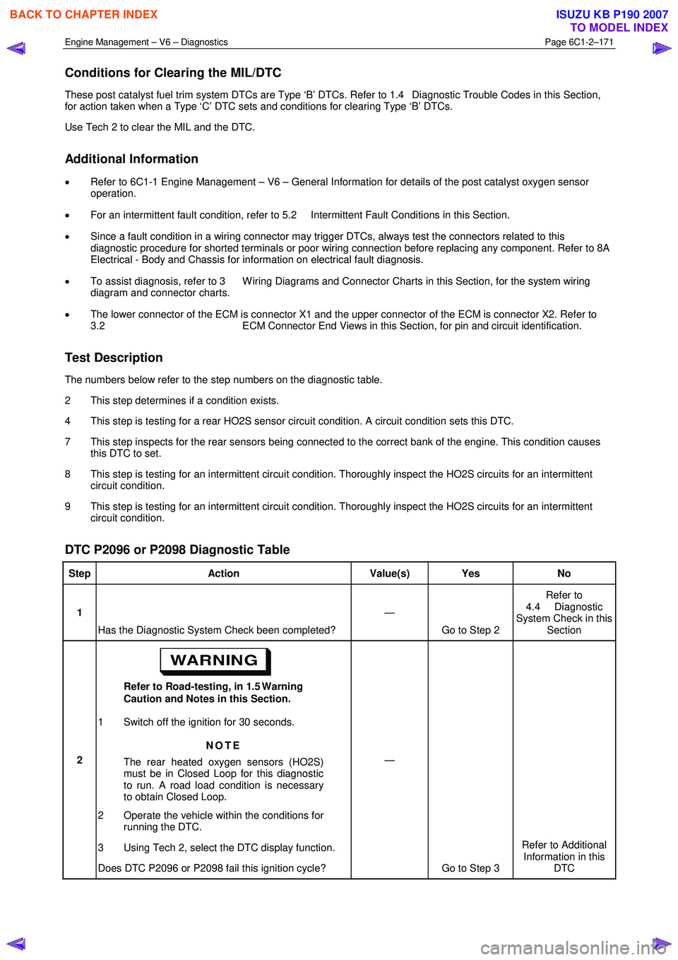
The numbers below refer to the step numbers on the diagnostic table.
2 This step determines if a condition exists.
4 This step is testing for a rear HO2S sensor circuit condition. A circuit condition sets this DTC.
7 This step inspects for the rear sensors being connected to the correct bank of the engine. This condition causes this DTC to set.
8 This step is testing for an intermittent circuit condition. Thoroughly inspect the HO2S circuits for an intermittent circuit condition.
9 This step is testing for an intermittent circuit condition. Thoroughly inspect the HO2S circuits for an intermittent circuit condition.
DTC P2096 or P2098 Diagnostic Table
Step Action Value(s) Yes No
1
Has the Diagnostic System Check been completed? —
Go to Step 2 Refer to
4.4 Diagnostic
System Check in this Section
2 Refer to Road-testing, in 1.5 Warning
Caution and Notes in this Section.
1 Switch off the ignition for 30 seconds.
NOTE
The rear heated oxygen sensors (HO2S)
must be in Closed Loop for this diagnostic
to run. A road load condition is necessary
to obtain Closed Loop.
2 Operate the vehicle within the conditions for running the DTC.
3 Using Tech 2, select the DTC display function.
Does DTC P2096 or P2098 fail this ignition cycle? —
Go to Step 3 Refer to Additional
Information in this DTC
BACK TO CHAPTER INDEX
TO MODEL INDEX
ISUZU KB P190 2007
Page 3454 of 6020
Engine Management – V6 – Diagnostics Page 6C1-2–176
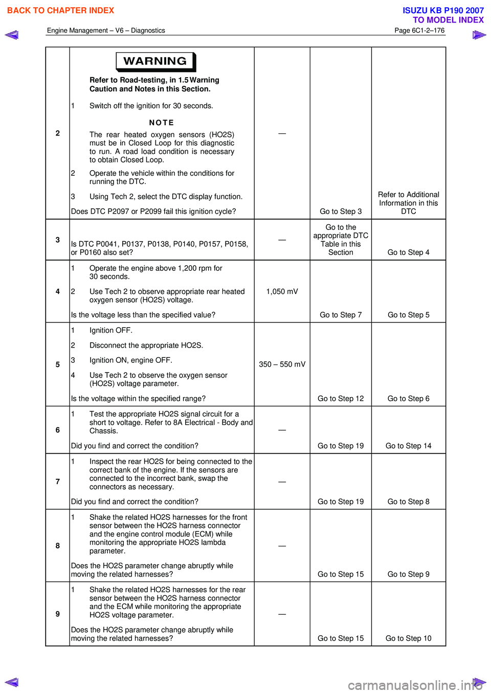
2 Refer to Road-testing, in 1.5 Warning
Caution and Notes in this Section.
1 Switch off the ignition for 30 seconds.
NOTE
The rear heated oxygen sensors (HO2S)
must be in Closed Loop for this diagnostic
to run. A road load condition is necessary
to obtain Closed Loop.
2 Operate the vehicle within the conditions for running the DTC.
3 Using Tech 2, select the DTC display function.
Does DTC P2097 or P2099 fail this ignition cycle? —
Go to Step 3 Refer to Additional
Information in this DTC
3 Is DTC P0041, P0137, P0138, P0140, P0157, P0158,
or P0160 also set? —
Go to the
appropriate DTC Table in this Section Go to Step 4
4 1 Operate the engine above 1,200 rpm for
30 seconds.
2 Use Tech 2 to observe appropriate rear heated oxygen sensor (HO2S) voltage.
Is the voltage less than the specified value? 1,050 mV
Go to Step 7 Go to Step 5
5 1 Ignition OFF.
2 Disconnect the appropriate HO2S.
3 Ignition ON, engine OFF.
4 Use Tech 2 to observe the oxygen sensor (HO2S) voltage parameter.
Is the voltage within the specified range? 350 – 550 mV
Go to Step 12 Go to Step 6
6 1 Test the appropriate HO2S signal circuit for a
short to voltage. Refer to 8A Electrical - Body and
Chassis.
Did you find and correct the condition? —
Go to Step 19 Go to Step 14
7 1 Inspect the rear HO2S for being connected to the
correct bank of the engine. If the sensors are
connected to the incorrect bank, swap the
connectors as necessary.
Did you find and correct the condition? —
Go to Step 19 Go to Step 8
8 1 Shake the related HO2S harnesses for the front
sensor between the HO2S harness connector
and the engine control module (ECM) while
monitoring the appropriate HO2S lambda
parameter.
Does the HO2S parameter change abruptly while
moving the related harnesses? —
Go to Step 15 Go to Step 9
9 1 Shake the related HO2S harnesses for the rear
sensor between the HO2S harness connector
and the ECM while monitoring the appropriate
HO2S voltage parameter.
Does the HO2S parameter change abruptly while
moving the related harnesses? —
Go to Step 15 Go to Step 10
BACK TO CHAPTER INDEX
TO MODEL INDEX
ISUZU KB P190 2007
Page 3525 of 6020
Engine Management – V6 – Service Operations Page 6C1-3–1
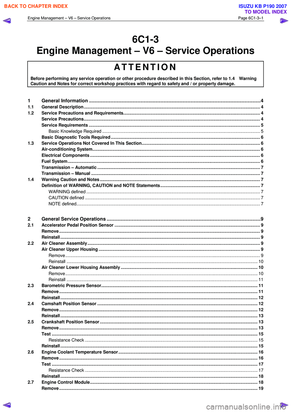
6C1-3
Engine Management – V6 – Service Operations
ATTENTION
Before performing any service operation or other procedure described in this Section, refer to 1.4 Warning
Caution and Notes for correct workshop practices with regard to safety and / or property damage.
1 General Information ............................................................................................................ ...................4
1.1 General Description ............................................................................................................ ................................... 4
1.2 Service Precautions and Requirements........................................................................................... .................... 4
Service Precautions............................................................................................................................................... 4
Service Requirements ........................................................................................................................................... 5
Basic Knowledge Required ....................................................................................................... ......................... 5
Basic Diagnostic Tools Required ......................................................................................................................... 6
1.3 Service Operations Not Covered In This Section................................................................................. ............... 6
Air-conditioning System........................................................................................................................................ 6
Electrical Components .......................................................................................................................................... 6
Fuel System ............................................................................................................................................................ 6
Transmission – Automatic ....................................................................................................... ............................. 7
Transmission – Manual ......................................................................................................................................... 7
1.4 Warning Caution and Notes .................................................................................................................................. 7
Definition of WARNING, CAUTION and NOTE Statements ............................................................................. .... 7
WARNING defined ............................................................................................................................................. 7
CAUTION defined .............................................................................................................................................. 7
NOTE defined..................................................................................................................................................... 7
2 General Service Operations ..................................................................................................... .............9
2.1 Accelerator Pedal Position Sensor .............................................................................................. ........................ 9
Remove ................................................................................................................................................................... 9
Reinstall .................................................................................................................................................................. 9
2.2 Air Cleaner Assembly ............................................................................................................................................ 9
Air Cleaner Upper Housing ...................................................................................................... ............................. 9
Remove .............................................................................................................................................................. 9
Reinstall ........................................................................................................................................................... 10
Air Cleaner Lower Housing Assembly ............................................................................................. .................. 10
Remove ............................................................................................................................................................ 10
Reinstall ........................................................................................................................................................... 11
2.3 Barometric Pressure Sensor..................................................................................................... .......................... 11
Remove ................................................................................................................................................................. 11
Reinstall ................................................................................................................................................................ 12
2.4 Camshaft Position Sensor ....................................................................................................... ........................... 12
Remove ................................................................................................................................................................. 12
Reinstall ................................................................................................................................................................ 13
2.5 Crankshaft Position Sensor ..................................................................................................... ........................... 13
Remove ................................................................................................................................................................. 13
Test ....................................................................................................................................................................... 15
Resistance Check ............................................................................................................... ............................. 15
Reinstall ................................................................................................................................................................ 15
2.6 Engine Coolant Temperature Sensor .............................................................................................. ................... 16
Remove ................................................................................................................................................................. 16
Test ....................................................................................................................................................................... 17
Resistance Check ............................................................................................................... ............................. 17
Reinstall ................................................................................................................................................................ 18
2.7 Engine Control Module.......................................................................................................... .............................. 18
Remove ................................................................................................................................................................. 19
BACK TO CHAPTER INDEX
TO MODEL INDEX
ISUZU KB P190 2007
Page 3531 of 6020
Engine Management – V6 – Service Operations Page 6C1-3–7
Transmission – Automatic
For automatic transmission sensors and components, refer to 7C4 Automatic Transmission – 4L60E – On-vehicle
Servicing.
Transmission – Manual
For manual transmission sensors and other components, refer to 7B1 Manual Transmission – V6.
1.4 Warning Caution and Notes
This Section contains various W ARNINGS, CAUTIONS and NOTE statements that you must observe carefully to reduce
the risk of death or injury during service, repair procedures or vehicle operation. Incorrect service or repair procedures
may damage the vehicle or cause operational faults. W ARNINGS, CAUTION and NOTE statements are not exhaustive.
GM Holden LTD can not possibly warn of all the potentially hazardous consequences of failure to follow these
instructions.
Definition of WARNING, CAUTION and NOTE Statements
Diagnosis and repair procedures in this Section contain both general and specific W ARNING, CAUTION and NOTE
statements. GM Holden LTD is dedicated to the presentation of service information that helps the technician to diagnose
and repair the systems necessary for proper operation of the vehicle. Certain procedures may present a hazard to the
technician if they are not followed in the recommended manner. W ARNING, CAUTION and NOTE statements are
designed to help prevent these hazards from occurring, but not all hazards can be foreseen.
WARNING defined
A W ARNING statement immediately precedes an operating procedure or maintenance practice which, if not correctly
followed, could result in death or injury. A W ARNING statement alerts you to take necessary action or not to take a
prohibited action. If a W ARNING statement is ignored, the following consequences may occur:
• Death or injury to the technician or other personnel working on the vehicle,
• Death or injury to other people in or near the workplace area, and / or
• Death or injury to the driver / or passenger(s) of the vehicle or other people, if the vehicle has been improperly
repaired.
CAUTION defined
A CAUTION statement immediately precedes an operating procedure or maintenance practice which, if not correctly
followed, could result in damage to or destruction of equipment, or corruption of data. If a CAUTION statement is ignored,
the following consequences may occur:
• Damage to the vehicle,
• Unnecessary vehicle repairs or component replacement,
• Faulty operation or performance of any system or component being repaired,
• Damage to any system or components which depend on the proper operation of the system or component being
repaired,
• Faulty operation or performance of any systems or components which depend on the proper operation or
performance of the system or component under repair,
• Damage to fasteners, basic tools or special tools and / or
• Leakage of coolant, lubricant or other vital fluids.
NOTE defined
A NOTE statement immediately precedes or follows an operating procedure, maintenance practice or condition that
requires highlighting. A NOTE statement also emphasises necessary characteristics of a diagnostic or repair procedure.
A NOTE statement is designed to:
• Clarify a procedure,
• Present additional information for accomplishing a procedure,
BACK TO CHAPTER INDEX
TO MODEL INDEX
ISUZU KB P190 2007