2007 ISUZU KB P190 warning
[x] Cancel search: warningPage 4888 of 6020
7D1-14 TRANSFER CONTROL SYSTEM
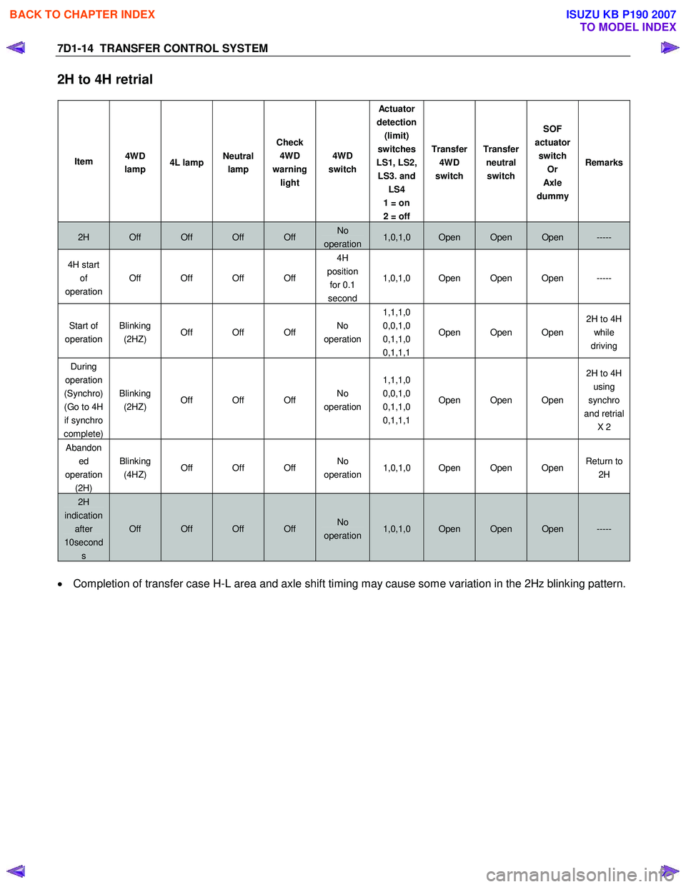
2H to 4H retrial
Item 4WD
lamp 4L lamp Neutral
lamp Check
4WD
warning light 4WD
switch Actu ato r
detection (limit)
switches
LS1, LS2, LS3. and LS4
1 = on
2 = off Transfer
4WD
switch Transfer
neutral switch SOF
actuator switch Or
Axl e
dummy Remarks
2H Off Off Off Off No
operation1,0,1,0 Open Open Open -----
4H start
of
operation Off Off Off Off 4H
position for 0.1
second 1,0,1,0 Open Open Open -----
Start of
operation Blinking
(2HZ) Off Off Off No
operation 1,1,1,0
0,0,1,0
0,1,1,0
0,1,1,1 Open Open Open
2H to 4H
while
driving
During
operation
(Synchro)
(Go to 4H if synchro
complete) Blinking
(2HZ) Off Off Off No
operation 1,1,1,0
0,0,1,0
0,1,1,0
0,1,1,1 Open Open Open 2H to 4H
using
synchro
and retrial X 2
Abandoned
operation (2H) Blinking
(4HZ) Off Off Off No
operation 1,0,1,0 Open Open Open Return to
2H
2H
indication
after
10second
s
Off Off Off Off No
operation1,0,1,0 Open Open Open -----
• Completion of transfer case H-L area and axle shift timing may cause some variation in the 2Hz blinking pattern.
BACK TO CHAPTER INDEX
TO MODEL INDEX
ISUZU KB P190 2007
Page 4890 of 6020
7D1-16 TRANSFER CONTROL SYSTEM
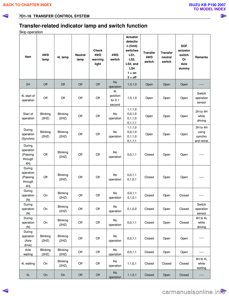
Transfer-related indicator lamp and switch function
Skip operation
Item 4WD
lamp 4L lamp Neutral
lamp Check
4WD
warning light 4WD
switch Actu ato r
detection (limit)
switches LS1,
LS2,
LS3. and LS4
1 = on
2 = off Transfer
4WD
switch Transfer
neutral switch SOF
actuator switch Or
Axl e
dummy Remarks
2H Off Off Off Off No
operation1,0,1,0 Open Open Open -----
4L start of
operation Off Off Off Off 4L
position for 0.1
second 1,0,1,0 Open Open Open
Switch
operation sensor
Start of
operation Blinking
(2HZ) Blinking
(2HZ) Off Off No
operation 1,1,1,0
0,0,1,0
0,1,1,0
0,1,1,1 Open Open Open
2H to 4H
while
driving
During
operation
(Synchro) Blinking
(2HZ) Blinking
(2HZ) Off Off No
operation 1,1,1,0
0,0,1,0
0,1,1,0
0,1,1,1 Open Open Open 2H to 4H
using
synchro
and retrial
During
operation (Passing through 4H) Off
Blinking
(2HZ) Off Off No
operation 0,0,1,1 Closed Open Open -----
During
operation (Passing through 4H) Off
Blinking
(2HZ) Off Off No
operation 0,0,1,1
0,1,0,1 Closed Open Open -----
During
operation
(N)
On Blinking
(2HZ) Off Off No
operation
0,0,1,1
0,1,0,1 Closed Open Closed -----
During
operation (N) On
Blinking
(2HZ) Off Off No
operation 0,1,0,0 Closed Open Closed Switch
operation sensor
During
operation (N) On
Blinking
(2HZ) Off Off No
operation 0,0,1,1 Closed Open Closed 4H to 4L
while
driving
During
operation (Axle
drive) Blinking
(2HZ) Blinking
(2HZ) Off Off No
operation 0,0,1,1 Closed Open Open
-----
Axle
waiting Blinking
(2HZ) Blinking
(2HZ) Off Off No
operation 0,0,1,1 Closed Open Open -----
4L waiting On Blinking
(2HZ) Off Off No
operation 1,1,0,1 Closed Closed Closed 4H to 4L
while
waiting
4L On On Off Off No
operation1,1,0,1 Closed Open Closed -----
BACK TO CHAPTER INDEX
TO MODEL INDEX
ISUZU KB P190 2007
Page 4893 of 6020
TRANSFER CONTROL SYSTEM 7D1-19
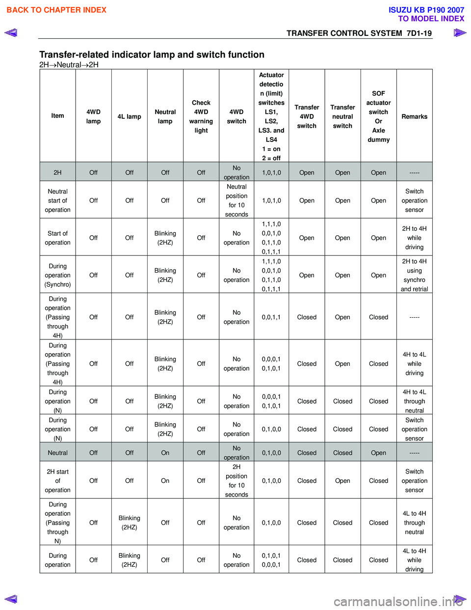
Transfer-related indicator lamp and switch function
2H→Neutral →2H
Item 4WD
lamp 4L lamp Neutral
lamp Check
4WD
warning light 4WD
switch Actu ato r
detection (limit)
switches LS1,
LS2,
LS3. and LS4
1 = on
2 = off Transfer
4WD
switch Transfer
neutral switch SOF
actuator switch Or
Axl e
dummy Remarks
2H Off Off Off Off No
operation1,0,1,0 Open Open Open -----
Neutral
start of
operation Off Off Off Off Neutral
position for 10
seconds 1,0,1,0 Open Open Open
Switch
operation sensor
Start of
operation Off Off Blinking
(2HZ) Off No
operation 1,1,1,0
0,0,1,0
0,1,1,0
0,1,1,1 Open Open Open
2H to 4H
while
driving
During
operation
(Synchro) Off Off
Blinking
(2HZ) Off No
operation 1,1,1,0
0,0,1,0
0,1,1,0
0,1,1,1 Open Open Open 2H to 4H
using
synchro
and retrial
During
operation (Passing through 4H) Off Off
Blinking
(2HZ) Off No
operation 0,0,1,1 Closed Open Closed -----
During
operation (Passing through 4H) Off Off
Blinking
(2HZ) Off No
operation 0,0,0,1
0,1,0,1 Closed Open Closed 4H to 4L
while
driving
During
operation
(N)
Off Off Blinking
(2HZ) Off No
operation
0,0,0,1
0,1,0,1 Closed Closed Closed
4H to 4L
through
neutral
During
operation (N) Off Off
Blinking
(2HZ) Off No
operation 0,1,0,0 Closed Closed Closed Switch
operation sensor
Neutral Off Off On Off No
operation0,1,0,0 Closed Closed Open -----
2H start of
operation Off Off On Off 2H
position for 10
seconds 0,1,0,0 Closed Open Closed
Switch
operation sensor
During
operation (Passing through N) Off
Blinking
(2HZ) Off Off No
operation 0,1,0,0 Closed Closed Closed 4L to 4H
through neutral
During
operation Off Blinking
(2HZ) Off Off No
operation 0,1,0,1
0,0,0,1 Closed Closed Closed 4L to 4H
while
driving
BACK TO CHAPTER INDEX
TO MODEL INDEX
ISUZU KB P190 2007
Page 4894 of 6020
7D1-20 TRANSFER CONTROL SYSTEM
Item 4WD
lamp 4L lamp Neutral
lamp Check
4WD
warning light 4WD
switch Actu ato r
detection (limit)
switches LS1,
LS2,
LS3. and LS4
1 = on
2 = off Transfer
4WD
switch Transfer
neutral switch SOF
actuator switch Or
Axl e
dummy Remarks
During
operation (4H
waiting) Off
Blinking
(2HZ) Off Off No
operation 0,0,1,1 Closed Closed Closed 4L to 4H
while
waiting
During
operation (Axle) Blinking
(2HZ) Off Off Off No
operation 0,1,1,1
0,1,1,0
0,0,1,0
1,1,1,0 Closed Open Closed
2H to 4H
while
driving
During
operation (Axle) Blinking
(2HZ) Off Off Off No
operation 0,1,1,1
0,1,1,0
0,0,1,0
1,1,1,0 Open Open Closed
Axle
driving
Axle
waiting
Blinking
(2HZ) Off Off Off No
operation1,0,1,0 Open Open Closed -----
2H Off Off Off Off No
operation1,0,1,0 Open Open Open -----
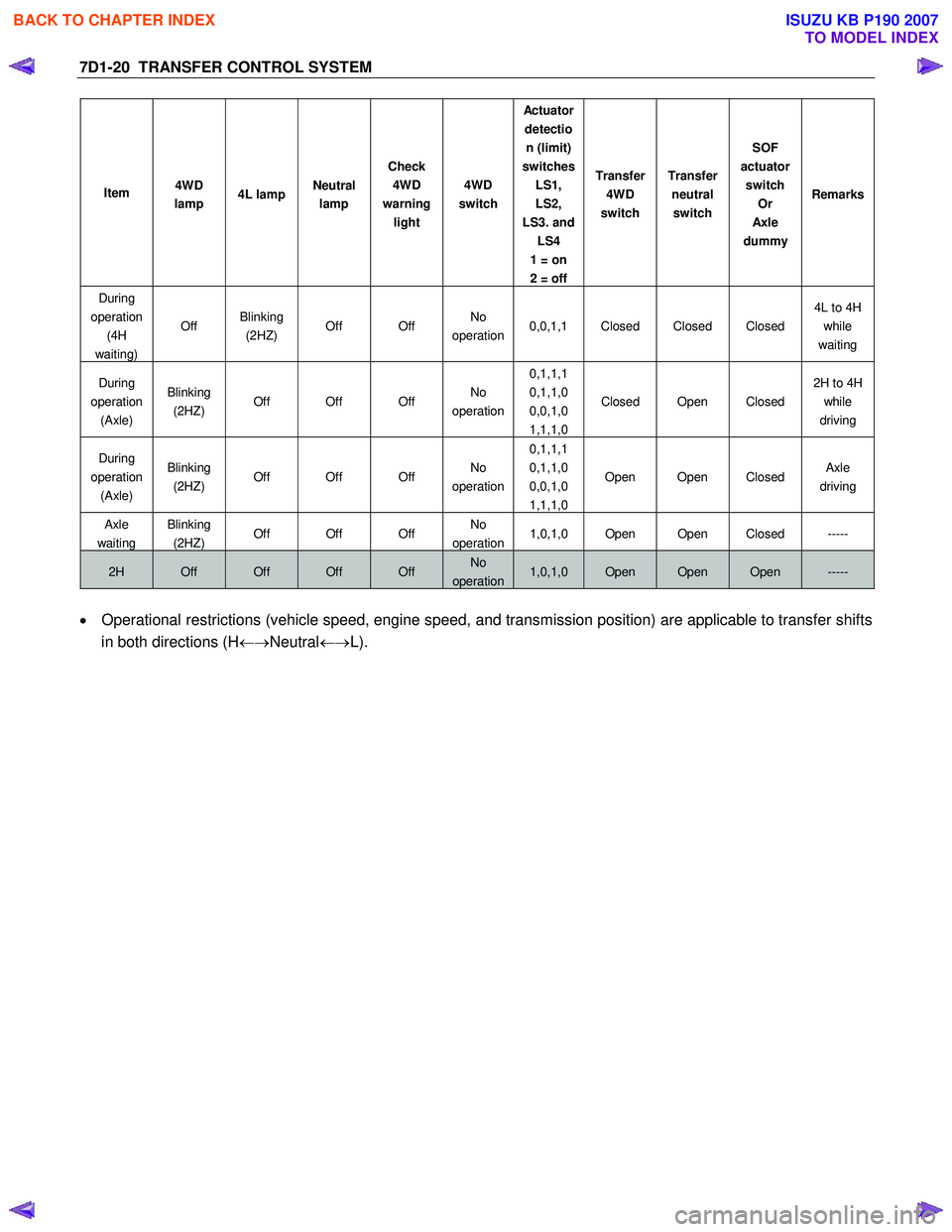
• Operational restrictions (vehicle speed, engine speed, and transmission position) are applicable to transfer shifts
in both directions (H ←→Neutral ←→L).
BACK TO CHAPTER INDEX
TO MODEL INDEX
ISUZU KB P190 2007
Page 4940 of 6020
8A-2 ELECTRICAL-BODY AND CHASSIS
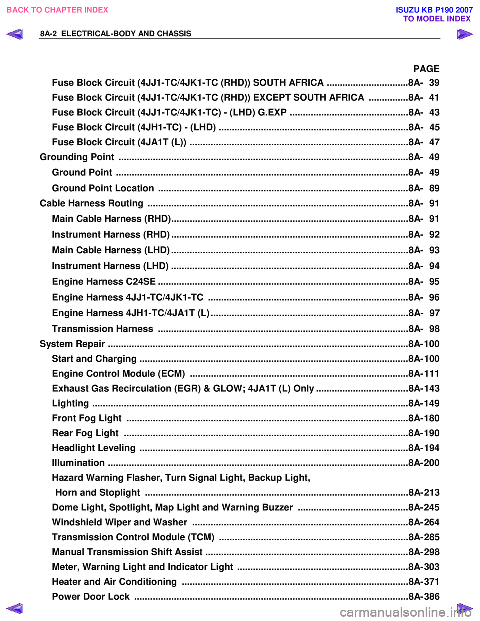
PAGE
Fuse Block Circuit (4JJ1-TC/4JK1-TC (RHD)) SOUTH AFRICA ...............................8A- 39
Fuse Block Circuit (4JJ1-TC/4JK1-TC (RHD)) EXCEPT SOUTH AFRICA ...............8A- 41
Fuse Block Circuit (4JJ1-TC/4JK1-TC) - (LHD) G.EXP .............................................8A- 43
Fuse Block Circuit (4JH1-TC) - (LHD) ........................................................................8A- 45
Fuse Block Circuit (4JA1T (L)) ...................................................................................8A- 47
Grounding Point ..............................................................................................................8 A- 49
Ground Point ...............................................................................................................8A- 49
Ground Point Location ...............................................................................................8A- 89
Cable Harness Routing ...................................................................................................8A- 91
Main Cable Harness (RHD)..........................................................................................8A- 91
Instrument Harness (RHD) ..........................................................................................8A- 92
Main Cable Harness (LHD) ..........................................................................................8A- 93
Instrument Harness (LHD) ..........................................................................................8A- 94
Engine Harness C24SE ...............................................................................................8A- 95
Engine Harness 4JJ1-TC/4JK1-TC ............................................................................8A- 96
Engine Harness 4JH1-TC/4JA1T (L) ...........................................................................8A- 97
Transmission Harness ...............................................................................................8A- 98
System Repair ................................................................................................................. .8A- 100
Start and Charging ......................................................................................................8A- 10 0
Engine Control Module (ECM) ...................................................................................8A- 111
Exhaust Gas Recirculation (EGR) & GLOW; 4JA1T (L) Only ...................................8A- 143
Lighting ...................................................................................................................... ..8A- 149
Front Fog Light ...........................................................................................................8A- 180
Rear Fog Light ............................................................................................................8A- 190
Headlight Leveling ......................................................................................................8A- 19 4
Illumination .................................................................................................................. 8A- 200
Hazard Warning Flasher, Turn Signal Light, Backup Light, Horn and Stoplight ....................................................................................................8A- 213
Dome Light, Spotlight, Map Light and Warning Buzzer ..........................................8A- 245
Windshield Wiper and Washer ..................................................................................8A- 264
Transmission Control Module (TCM) ........................................................................8A- 285
Manual Transmission Shift Assist .............................................................................8A- 298
Meter, Warning Light and Indicator Light .................................................................8A- 303
Heater and Air Conditioning ......................................................................................8A- 371
Power Door Lock ........................................................................................................8A- 386
BACK TO CHAPTER INDEX
TO MODEL INDEX
ISUZU KB P190 2007
Page 5151 of 6020
ELECTRICAL-BODY AND CHASSIS 8A-213
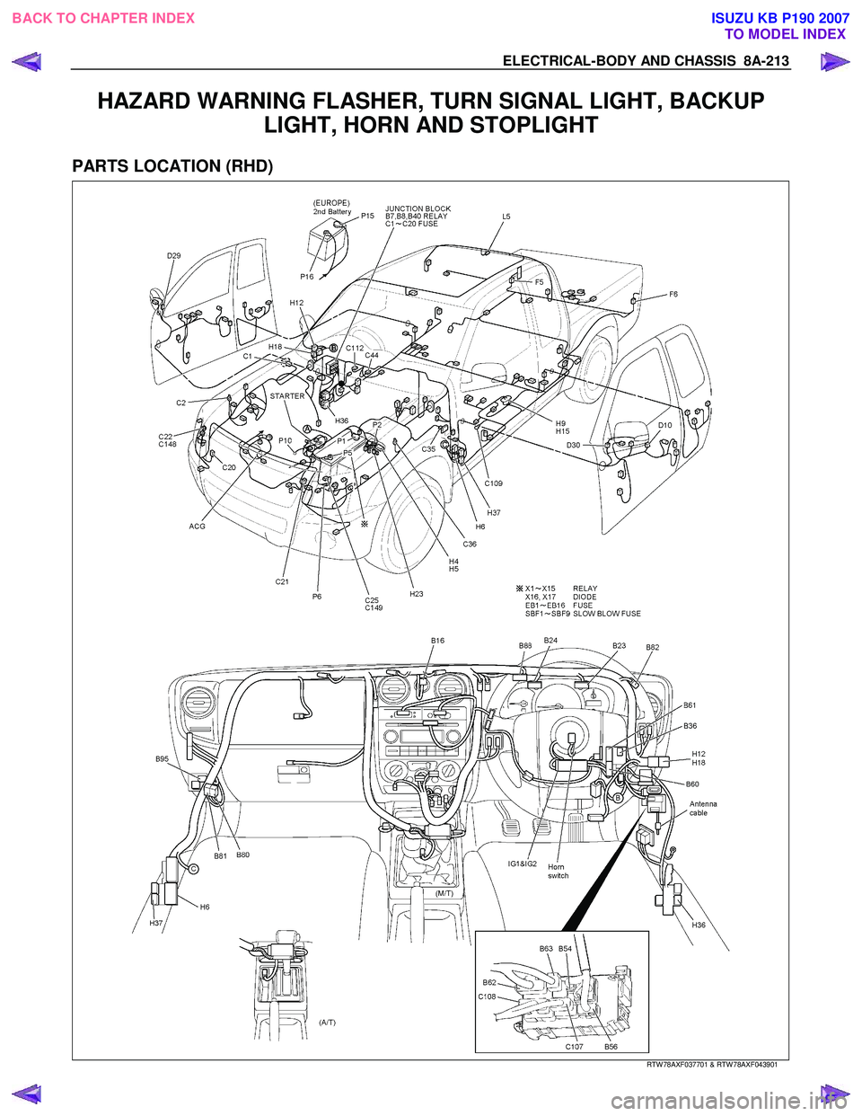
HAZARD WARNING FLASHER, TURN SIGNAL LIGHT, BACKUP LIGHT, HORN AND STOPLIGHT
PARTS LOCATION (RHD)
RTW 78AXF037701 & RTW 78AXF043901
BACK TO CHAPTER INDEX
TO MODEL INDEXISUZU KB P190 2007
Page 5168 of 6020
8A-230 ELECTRICAL-BODY AND CHASSIS
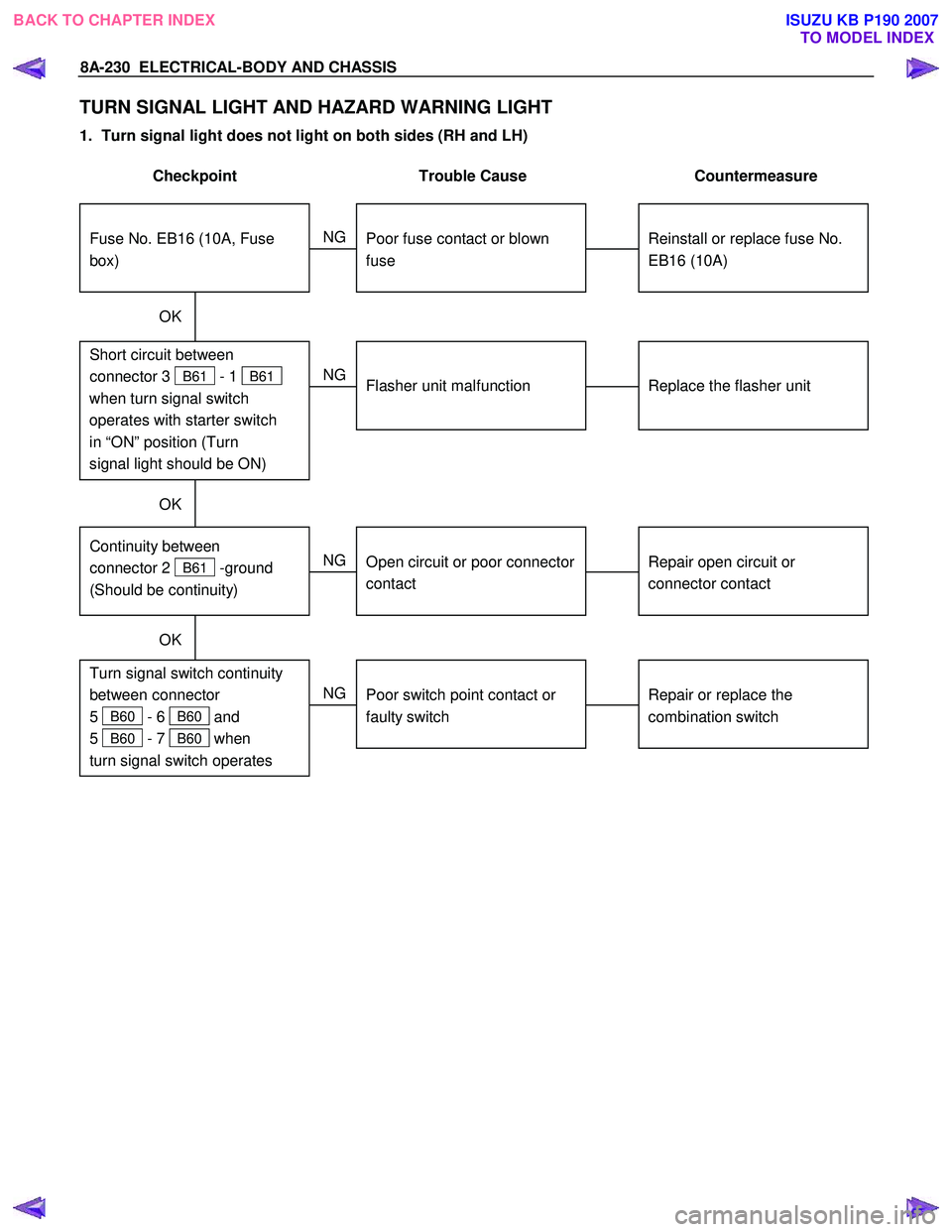
TURN SIGNAL LIGHT AND HAZARD WARNING LIGHT
1. Turn signal light does not light on both sides (RH and LH)
Checkpoint Trouble Cause Countermeasure
Replace the flasher unit
Flasher unit malfunction
NG
Repair or replace the
combination switch
Turn signal switch continuity
between connector
5
B60 - 6 B60 and
5
B60 - 7 B60 when
turn signal switch operates
Short circuit between
connector 3
B61 - 1 B61
when turn signal switch
operates with starter switch
in “ON” position (Turn
signal light should be ON)
Poor switch point contact or
faulty switch
NG
OK
Reinstall or replace fuse No.
EB16 (10A)
Fuse No. EB16 (10A, Fuse
box)
Poor fuse contact or blown
fuse
NG
OK
OK
Repair open circuit or
connector contact
Continuity between
connector 2
B61 -ground
(Should be continuity)
Open circuit or poor connector
contact
NG
BACK TO CHAPTER INDEX TO MODEL INDEXISUZU KB P190 2007
Page 5169 of 6020
ELECTRICAL-BODY AND CHASSIS 8A-231
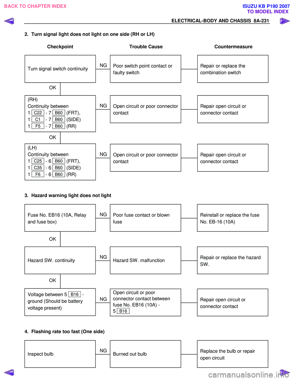
2. Turn signal light does not light on one side (RH or LH)
Checkpoint Trouble Cause Countermeasure
Repair open circuit or
connector contact
Open circuit or poor connector
contact
NG
(LH)
Continuity between
1
C25 - 6 B60 (FRT),
1
C35 - 6 B60 (SIDE)
1
F6 - 6 B60 (RR)
(RH)
Continuity between
1
C22 - 7 B60 (FRT),
1
C1 - 7 B60 (SIDE)
1
F5 - 7 B60 (RR)
Repair or replace the
combination switch
Turn signal switch continuity
Poor switch point contact or
faulty switch
NG
OK
OK
Repair open circuit or
connector contact
Open circuit or poor connector
contact
NG
3. Hazard warning light does not light
Repair or replace the hazard
SW .
Hazard SW . malfunction
NG
Voltage between 5
B16 -
ground (Should be battery
voltage present)
Hazard SW . continuity
Reinstall or replace the fuse
No. EB-16 (10A)
Fuse No. EB16 (10A, Relay
and fuse box)
Poor fuse contact or blown
fuse
NG
OK
OK
Repair open circuit or
connector contact
Open circuit or poor
connector contact between
fuse No. EB16 (10A) -
5
B16
NG
4. Flashing rate too fast (One side)
Replace the bulb or repair
open circuitInspect bulbBurned out bulb
NG
BACK TO CHAPTER INDEX TO MODEL INDEXISUZU KB P190 2007