2007 ISUZU KB P190 warning
[x] Cancel search: warningPage 5482 of 6020
8A-544 ELECTRICAL-BODY AND CHASSIS
Keyless Entry System
General Description
The system’s main features are summarized as follows.
・ Keyless entry with visual feedback
・ Highly secure encrypted transmission format
incorporating rolling code strategy
・ Field programmable remote keys
・ Door lock control
・ Illuminated entry with fade out
・ Illuminated exit
・ Remote door lock / ignition key interlock
・ Door ajar warning indicator in the cluster
BACK TO CHAPTER INDEX
TO MODEL INDEXISUZU KB P190 2007
Page 5579 of 6020
Cruise Control – HFV6 Page 8C–1
8C
Cruise Control – HFV6
ATTENTION
Before performing any Service Operation or other procedure described in this Section, refer to General Information Warnings, Cautions and Notes for correct workshop practices with regard to safety and/or property damage.
1 General Information ...............................................................................................................................3
1.1 WARNINGS, CAUTIONS and NOTES................................................................................................... ................. 3
Definition of WARNING, CAUTION and NOTE Statements ............................................................................. .... 3
WARNING Defined............................................................................................................................................. 3
CAUTION Defined .............................................................................................................................................. 3
NOTE Defined .................................................................................................................................................... 4
1.2 System Components .............................................................................................................. ............................... 4
Cruise Control Switch Assembly ................................................................................................. ....................... 5
Instrument Cluster Assembly ............................................................................................................................. 5
Clutch Pedal Switch (Manual Only) .............................................................................................. ...................... 5
Stop Lamp Switch Assembly .............................................................................................................................. 5
Powertrain Interface Module .............................................................................................................................. 6
Engine Control Module ....................................................................................................................................... 6
Throttle Actuator Control (TAC) Assembly ....................................................................................... .................. 6
1.3 System Operation .................................................................................................................................................. 6
Preliminary Information......................................................................................................................................... 6
Enabled and Disabled ........................................................................................................... ............................. 6
Activated and Deactivated...................................................................................................... ............................ 7
Enabling the Cruise Control.................................................................................................... .............................. 7
Brake Before Cruise .............................................................................................................................................. 7
Activating the Cruise Control .................................................................................................. ............................. 7
Deactivating the Cruise Control ................................................................................................ ........................... 7
Pressing the Brake Pedal ................................................................................................................................... 7
Pressing the Cruise ON–OFF Button .............................................................................................. ................... 8
Rotating the Cruise Control Switch Assembly .................................................................................... ................ 8
Pressing the Clutch Pedal (Manual Vehicles Only) ............................................................................... ............. 8
Decelerating While Cruise Control is Activated ................................................................................. ................. 8
Resuming a Speed After Cruise Control Has Been Deactivated ..................................................................... .. 8
Accelerating While Cruise Control is Activated .................................................................................................. 8
Using the Cruise Control Switch Assembly ........................................................................................................ 8
Pressing the Accelerator Pedal .......................................................................................................................... 8
2 Diagnostics .............................................................................................................................................9
2.1 Diagnostic General Information............................................................................................................................ 9
Basic Knowledge Required ................................................................................................................................... 9
Basic Diagnostic Tools Required ......................................................................................................................... 9
Tech 2 Data List ................................................................................................................................................... 10
2.2 Diagnostic Systems Check ....................................................................................................... .......................... 10
Diagnostic Systems Check ................................................................................................................................. 10
2.3 Wiring Diagrams .................................................................................................................................................. 12
2.4 Cruise Control Inoperative / Malfunctioning.................................................................................... .................. 14
Circuit Description ............................................................................................................................................ 14
Manual Vehicles Only........................................................................................................... ............................ 14
Test Description ............................................................................................................................................... 14
Diagnostic Table Notes ......................................................................................................... ........................... 14
Diagnostic Table............................................................................................................................................... 14
SECTION
BACK TO CHAPTER INDEX
TO MODEL INDEX
ISUZU KB P190 2007
Page 5581 of 6020
Cruise Control – HFV6 Page 8C–3
1 General Information
A new cruise control system has been introduced due to changes in the powertrain architecture and components. There
is no longer a cruise control module; instead the management has been taken over by the engine control module (ECM).
To the user, the system operates as previously, with all controls from the cruise control switch assembly and the cruise
control messages presented by the instrument cluster. For vehicles fitted with the HFV6 engine refer to 1.3 System
Operation .
The cruise control system now has an
additional fail-safe feature. The brake pedal
must be pressed in the ignition cycle for the
cruise control to be engaged. The cruise
control will not engage until this is done.
1.1 WARNINGS, CAUTIONS and NOTES
This Section contains various W ARNINGS, CAUTIONS and NOTE statements that you must observe carefully to reduce
the risk of death or injury during service, repair procedures or vehicle operation. Incorrect service or repair procedures
may damage the vehicle or cause operational faults. W ARNINGS, CAUTION and NOTE statements are not exhaustive.
GM HOLDEN LTD can not possibly warn of all the potentially hazardous consequences of failure to follow these
instructions.
Definition of WARNING, CAUTION and NOTE Statements
Diagnosis and repair procedures in this Section contain both general and specific W ARNING, CAUTION and NOTE
statements. GM HOLDEN LTD is dedicated to the presentation of service information that helps the technician to
diagnose and repair the systems necessary for proper operation of the vehicle. Certain procedures may present a hazard
to the technician if they are not followed in the recommended manner. W ARNING, CAUTION and NOTE statements are
designed to help prevent these hazards from occurring, but not all hazards can be foreseen.
WARNING Defined
A W ARNING statement immediately precedes an operating procedure or maintenance practice which, if not correctly
followed, could result in death or injury. A WARNING statement alerts you to take necessary action or not to take a
prohibited action. If a W ARNING statement is ignored, the following consequences may occur:
• Death or injury to the technician or other personnel working on the vehicle,
• Death or injury to other people in or near the workplace area, and / or
• Death or injury to the driver / or passenger(s) of the vehicle or other people, if the vehicle has been improperly
repaired.
CAUTION Defined
A CAUTION statement immediately precedes an operating procedure or maintenance practice which, if not correctly
followed, could result in damage to or destruction of equipment, or corruption of data. If a CAUTION statement is ignored,
the following consequences may occur:
• Damage to the vehicle,
• Unnecessary vehicle repairs or component replacement,
• Faulty operation or performance of any system or component being repaired,
• Damage to any system or components which depend on the proper operation of the system or component being
repaired,
• Faulty operation or performance of any systems or components which depend on the proper operation or
performance of the system or component under repair,
• Damage to fasteners, basic tools or special tools and / or
• Leakage of coolant, lubricant or other vital fluids.
BACK TO CHAPTER INDEX
TO MODEL INDEXISUZU KB P190 2007
Page 5583 of 6020
Cruise Control – HFV6 Page 8C–5
Legend
1 Engine Control Module
2 Throttle Actuator Control (TAC) Assembly
3 Cruise Control Switch Assembly
4 Instrument Cluster Assembly 5 Cruise Control ON / OFF Switch
6 Powertrain Interface Module
7 Clutch Pedal Switch Assembly (Manual Only)
8 Stop Lamp Switch Assembly
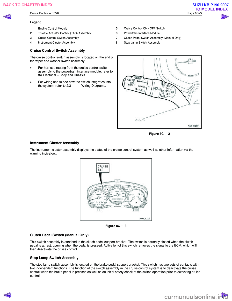
Cruise Control Switch Assembly
The cruise control switch assembly is located on the end of
the wiper and washer switch assembly.
• For harness routing from the cruise control switch
assembly to the powertrain interface module, refer to
8A Electrical – Body and Chassis.
• For wiring and to see how the switch integrates into
the system, refer to 2.3 W iring Diagrams.
Figure 8C – 2
Instrument Cluster Assembly
The instrument cluster assembly displays the status of the cruise control system as well as other information via the
warning indicators.
Figure 8C – 3
Clutch Pedal Switch (Manual Only)
This switch assembly is attached to the clutch pedal support bracket. The switch is normally closed when the clutch
pedal is at rest, opening when the pedal is pressed. Activation of this switch removes the signal to the ECM, which will
then deactivate the cruise control.
Stop Lamp Switch Assembly
The stop lamp switch assembly is located on the brake pedal support bracket. This switch has two sets of contacts with
two independent functions. The function of the switch assembly in the cruise control system is to deactivate the cruise
control when the brake pedal is pressed as well as an initial safety check of the switch operation prior to activating cruise
control.
BACK TO CHAPTER INDEX TO MODEL INDEXISUZU KB P190 2007
Page 5585 of 6020
Cruise Control – HFV6 Page 8C–7
Activated and Deactivated
When the cruise control is enabled, the vehicle speed must be above 40 km/h and the cruise control switch assembly
pressed to SET–COAST, the cruise control will be activated and the vehicle will maintain the set speed. When
deactivated by the methods described within this section, the vehicle will no longer maintain the set speed, but the cruise
control will still be engaged.
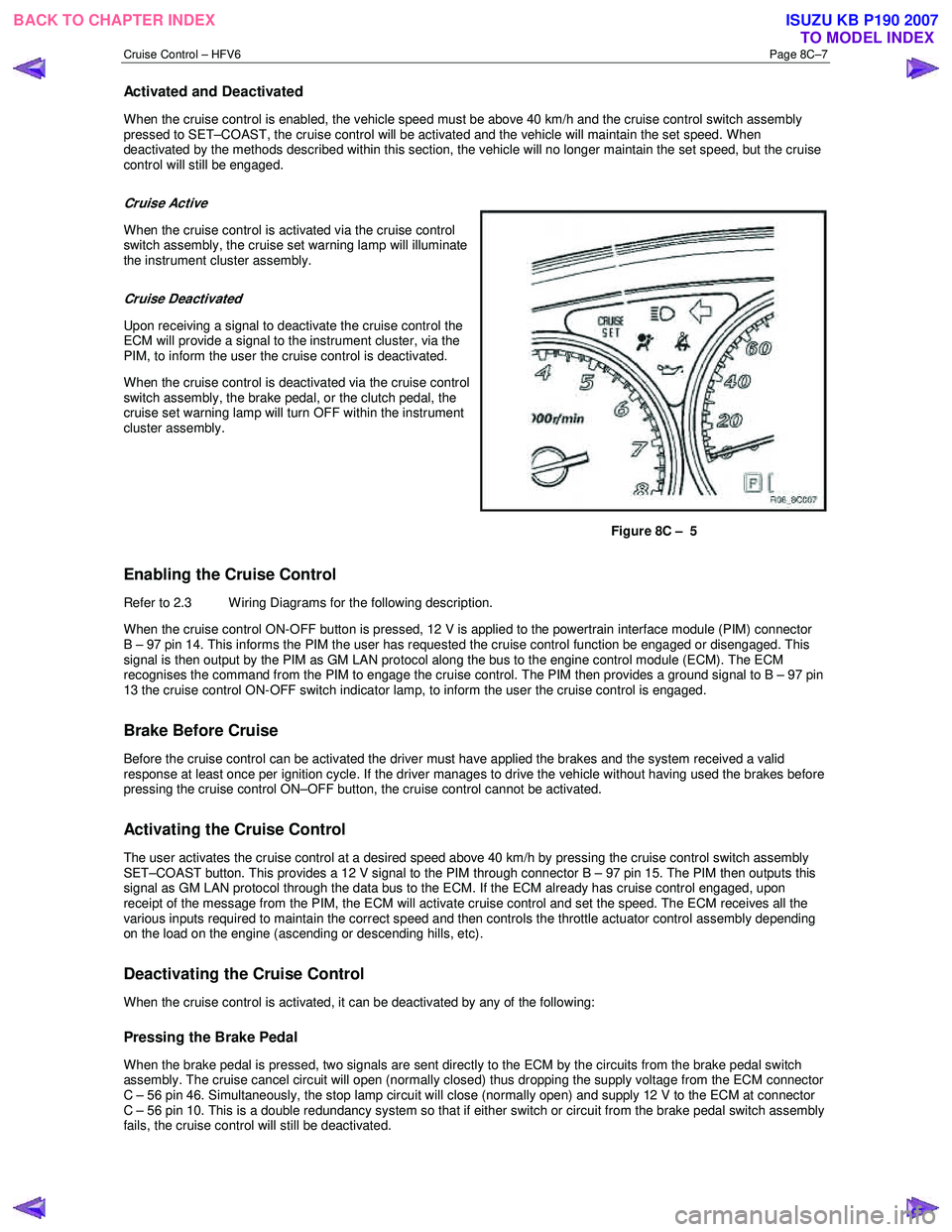
Cruise Active
When the cruise control is activated via the cruise control
switch assembly, the cruise set warning lamp will illuminate
the instrument cluster assembly.
Cruise Deactivated
Upon receiving a signal to deactivate the cruise control the
ECM will provide a signal to the instrument cluster, via the
PIM, to inform the user the cruise control is deactivated.
When the cruise control is deactivated via the cruise control
switch assembly, the brake pedal, or the clutch pedal, the
cruise set warning lamp will turn OFF within the instrument
cluster assembly.
Figure 8C – 5
Enabling the Cruise Control
Refer to 2.3 Wiring Diagrams for the following description.
W hen the cruise control ON-OFF button is pressed, 12 V is applied to the powertrain interface module (PIM) connector
B – 97 pin 14. This informs the PIM the user has requested the cruise control function be engaged or disengaged. This
signal is then output by the PIM as GM LAN protocol along the bus to the engine control module (ECM). The ECM
recognises the command from the PIM to engage the cruise control. The PIM then provides a ground signal to B – 97 pin
13 the cruise control ON-OFF switch indicator lamp, to inform the user the cruise control is engaged.
Brake Before Cruise
Before the cruise control can be activated the driver must have applied the brakes and the system received a valid
response at least once per ignition cycle. If the driver manages to drive the vehicle without having used the brakes before
pressing the cruise control ON–OFF button, the cruise control cannot be activated.
Activating the Cruise Control
The user activates the cruise control at a desired speed above 40 km/h by pressing the cruise control switch assembly
SET–COAST button. This provides a 12 V signal to the PIM through connector B – 97 pin 15. The PIM then outputs this
signal as GM LAN protocol through the data bus to the ECM. If the ECM already has cruise control engaged, upon
receipt of the message from the PIM, the ECM will activate cruise control and set the speed. The ECM receives all the
various inputs required to maintain the correct speed and then controls the throttle actuator control assembly depending
on the load on the engine (ascending or descending hills, etc).
Deactivating the Cruise Control
When the cruise control is activated, it can be deactivated by any of the following:
Pressing the Brake Pedal
When the brake pedal is pressed, two signals are sent directly to the ECM by the circuits from the brake pedal switch
assembly. The cruise cancel circuit will open (normally closed) thus dropping the supply voltage from the ECM connector
C – 56 pin 46. Simultaneously, the stop lamp circuit will close (normally open) and supply 12 V to the ECM at connector
C – 56 pin 10. This is a double redundancy system so that if either switch or circuit from the brake pedal switch assembly
fails, the cruise control will still be deactivated.
BACK TO CHAPTER INDEX TO MODEL INDEXISUZU KB P190 2007
Page 5636 of 6020
SUPPLEMENTAL RESTRAINT SYSTEM 9A-1
SECTION 9A
SUPPLEMENTAL RESTRAINT SYSTEM (SRS)
TABLE OF CONTENTS
PAGE
Service Precaution ....................................................................................................... 9A- 4
General Description...................................................................................................... 9A- 4 Restraint Devices ..................................................................................................... 9A- 4
System Description .................................................................................................. 9A- 5
Circuit Diagram ............................................................................................................. 9A- 6
SRS Component And Wiring Location View .............................................................. 9A- 10
Component Description ............................................................................................... 9A- 14 SRS Control Unit ...................................................................................................... 9A- 14
"SRS" Warning Lamp .............................................................................................. 9A- 14
SRS Coil Assembly .................................................................................................. 9A- 15
Air Bag Assemblies.................................................................................................. 9A- 15
Steering Column ...................................................................................................... 9A- 16
Knee Bolster ............................................................................................................. 9A- 16
Definitions .................................................................................................................... . 9A- 16
Diagnosis...................................................................................................................... . 9A- 18
Diagnostic Trouble Codes ....................................................................................... 9A- 18
Scan Tool Diagnostics............................................................................................. 9A- 18
Use Of Special Tools ............................................................................................... 9A- 18
SRS Connec tor Body Face Vie ws ............................................................................. ..9 A- 19
Repairs And Inspec tions Required After A n A ccident ............................................ ..9 A- 20
Accident With Deployment-Component Replacement And Inspections ............. 9A- 20
Accident With or Without Deployment-Component Inspection ........................... 9A- 20
SRS Control Unit Replacement Guidelines ........................................................... 9A- 20
Wiring Damage ......................................................................................................... 9A- 20
SRS Connector (Plastic Body And Terminal Metal Pin) Damage ......................... 9A- 20
SRS Wire Pigtail Damage ........................................................................................ 9A- 20
PAGE 1 OF 3
BACK TO CHAPTER INDEX TO MODEL INDEXISUZU KB P190 2007
Page 5639 of 6020
9A-4 SUPPLEMENTAL RESTRAINT SYSTEM
Service Precaution
WARNING: THIS VEHICLE HAS A SUPPLEMENTAL
RESTRAINT SYSTEM (SRS). REFER TO THE SRS
COMPONENT AND WIRING LOCATION VIEW IN
ORDER TO DETERMINE WHETHER YOU ARE
PERFORMING A SERVICE ON, OR NEAR, THE SRS
COMPONENTS OR THE SRS WIRING. WHEN YOU
ARE PERFORMING A SERVICE ON OR NEAR THE
SRS COMPONENTS OR THE SRS WIRING, REFER
TO THE SRS SERVICE INFORMATION. FAILURE
TO FOLLOW WARNINGS COULD RESULT IN
POSSIBLE AIR BAG DEPLOYMENT, PERSONAL
INJURY, OR OTHERWISE UNNECESSARY SRS
SYSTEM REPAIRS.
CAUTION: Always use the correct fastener in the
proper location. When you replace a fastener, use
ONLY the exact part number for that application.
ISUZU/GM will call out those fasteners that require
a replacement after removal. ISUZU/GM will also
call out the fasteners that require thread lockers o
r
thread sealant. UNLESS OTHERWISE SPECIFIED,
do not use supplemental coatings (paints,
greases, or other corrosion inhibitors) on threaded
fasteners or fastener joint interfaces. Generally,
such coatings adversely affect the fastener torque
and the joint clamping force, and may damage the
fastener. When you install fasteners, use the
correct tightening sequence and specifications.
Following these instructions can help you avoid
damage to parts and systems.
General Description
CAUTION: When fasteners are removed, always
reinstall them at the same location from which
they were removed. If a fastener needs to be
replaced, use the correct part number fastener fo
r
that application. If the correct part numbe
r
fastener is not available, a fastener of equal size
and strength (or stronger) may be used.
Fasteners that are not reused, and those requiring
thread locking compound will be called out. The
correct torque value must be used when installing
fasteners that require it. If the above conditions
are not followed, parts or system damage could
result.
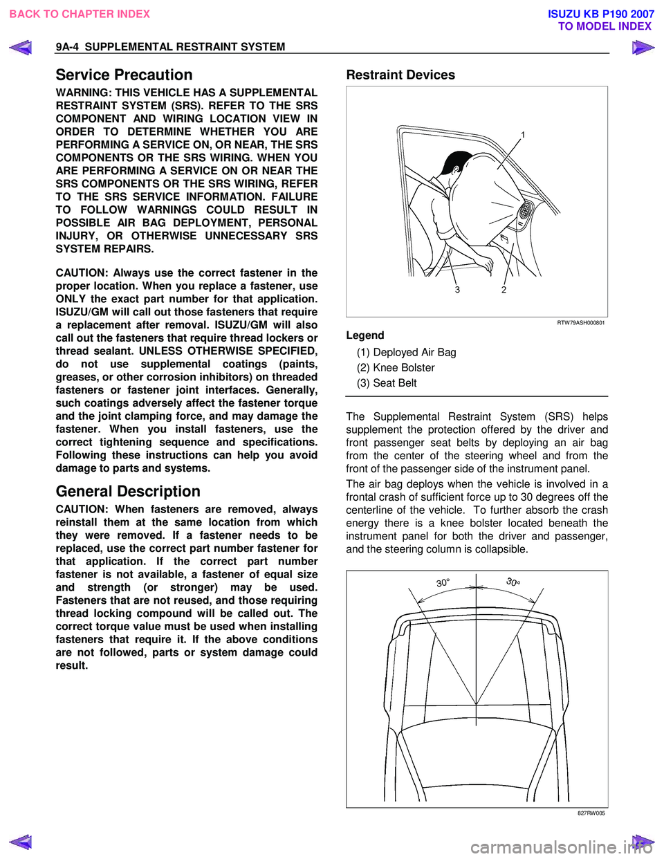
Restraint Devices
RTW 79ASH000801
Legend
(1) Deployed Air Bag
(2) Knee Bolster
(3) Seat Belt
The Supplemental Restraint System (SRS) helps
supplement the protection offered by the driver and
front passenger seat belts by deploying an air bag
from the center of the steering wheel and from the
front of the passenger side of the instrument panel.
The air bag deploys when the vehicle is involved in a
frontal crash of sufficient force up to 30 degrees off the
centerline of the vehicle. To further absorb the crash
energy there is a knee bolster located beneath the
instrument panel for both the driver and passenger,
and the steering column is collapsible.
827RW 005
BACK TO CHAPTER INDEX TO MODEL INDEXISUZU KB P190 2007
Page 5640 of 6020
SUPPLEMENTAL RESTRAINT SYSTEM 9A-5
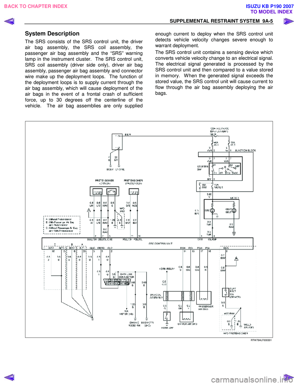
System Description
The SRS consists of the SRS control unit, the driver
air bag assembly, the SRS coil assembly, the
passenger air bag assembly and the “SRS” warning
lamp in the instrument cluster. The SRS control unit,
SRS coil assembly (driver side only), driver air bag
assembly, passenger air bag assembly and connecto
r
wire make up the deployment loops. The function of
the deployment loops is to supply current through the
air bag assembly, which will cause deployment of the
air bags in the event of a frontal crash of sufficient
force, up to 30 degrees off the centerline of the
vehicle. The air bag assemblies are only supplied
enough current to deploy when the SRS control unit
detects vehicle velocity changes severe enough to
warrant deployment.
The SRS control unit contains a sensing device which
converts vehicle velocity change to an electrical signal.
The electrical signal generated is processed by the
SRS control unit and then compared to a value stored
in memory. W hen the generated signal exceeds the
stored value, the SRS control unit will cause current to
flow through the air bag assembly deploying the ai
r
bags.
RTW 79ALF000301
BACK TO CHAPTER INDEX TO MODEL INDEXISUZU KB P190 2007