2007 ISUZU KB P190 warning
[x] Cancel search: warningPage 4426 of 6020
7A2-142 TRANSMISSION CONTROL SYSTEM (JR405E)
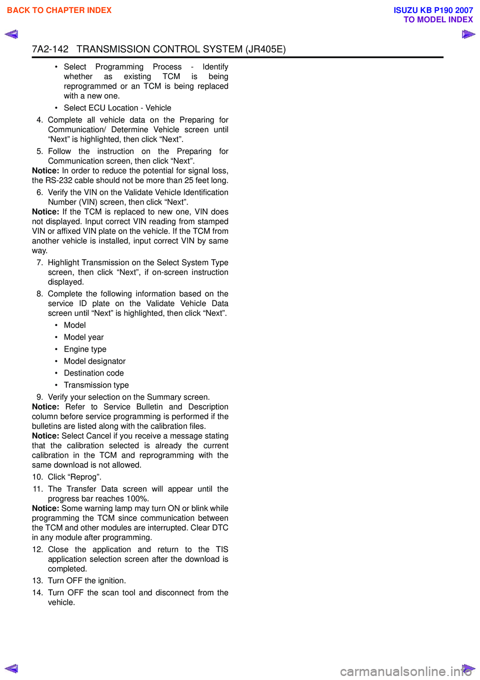
• Select Programming Process - Identifywhether as existing TCM is being
reprogrammed or an TCM is being replaced
with a new one.
• Select ECU Location - Vehicle
4. Complete all vehicle data on the Preparing for Communication/ Determine Vehicle screen until
“Next” is highlighted, then click “Next”.
5. Follow the instruction on the Preparing for Communication screen, then click “Next”.
Notice: In order to reduce the potential for signal loss,
the RS-232 cable should not be more than 25 feet long.
6. Verify the VIN on the Validate Vehicle Identification Number (VIN) screen, then click “Next”.
Notice: If the TCM is replaced to new one, VIN does
not displayed. Input correct VIN reading from stamped
VIN or affixed VIN plate on the vehicle. If the TCM from
another vehicle is installed, input correct VIN by same
way.
7. Highlight Transmission on the Select System Type screen, then click “Next”, if on-screen instruction
displayed.
8. Complete the following information based on the service ID plate on the Validate Vehicle Data
screen until “Next” is highlighted, then click “Next”.
• Model
• Model year
• Engine type
• Model designator
• Destination code
• Transmission type
9. Verify your selection on the Summary screen.
Notice: Refer to Service Bulletin and Description
column before service programming is performed if the
bulletins are listed along with the calibration files.
Notice: Select Cancel if you receive a message stating
that the calibration selected is already the current
calibration in the TCM and reprogramming with the
same download is not allowed.
10. Click “Reprog”.
11. The Transfer Data screen will appear until the progress bar reaches 100%.
Notice: Some warning lamp may turn ON or blink while
programming the TCM since communication between
the TCM and other modules are interrupted. Clear DTC
in any module after programming.
12. Close the application and return to the TIS application selection screen after the download is
completed.
13. Turn OFF the ignition.
14. Turn OFF the scan tool and disconnect from the vehicle.
BACK TO CHAPTER INDEX
TO MODEL INDEX
ISUZU KB P190 2007
Page 4609 of 6020
MANUAL TRANSMISSION 7B1-3
Service Precaution
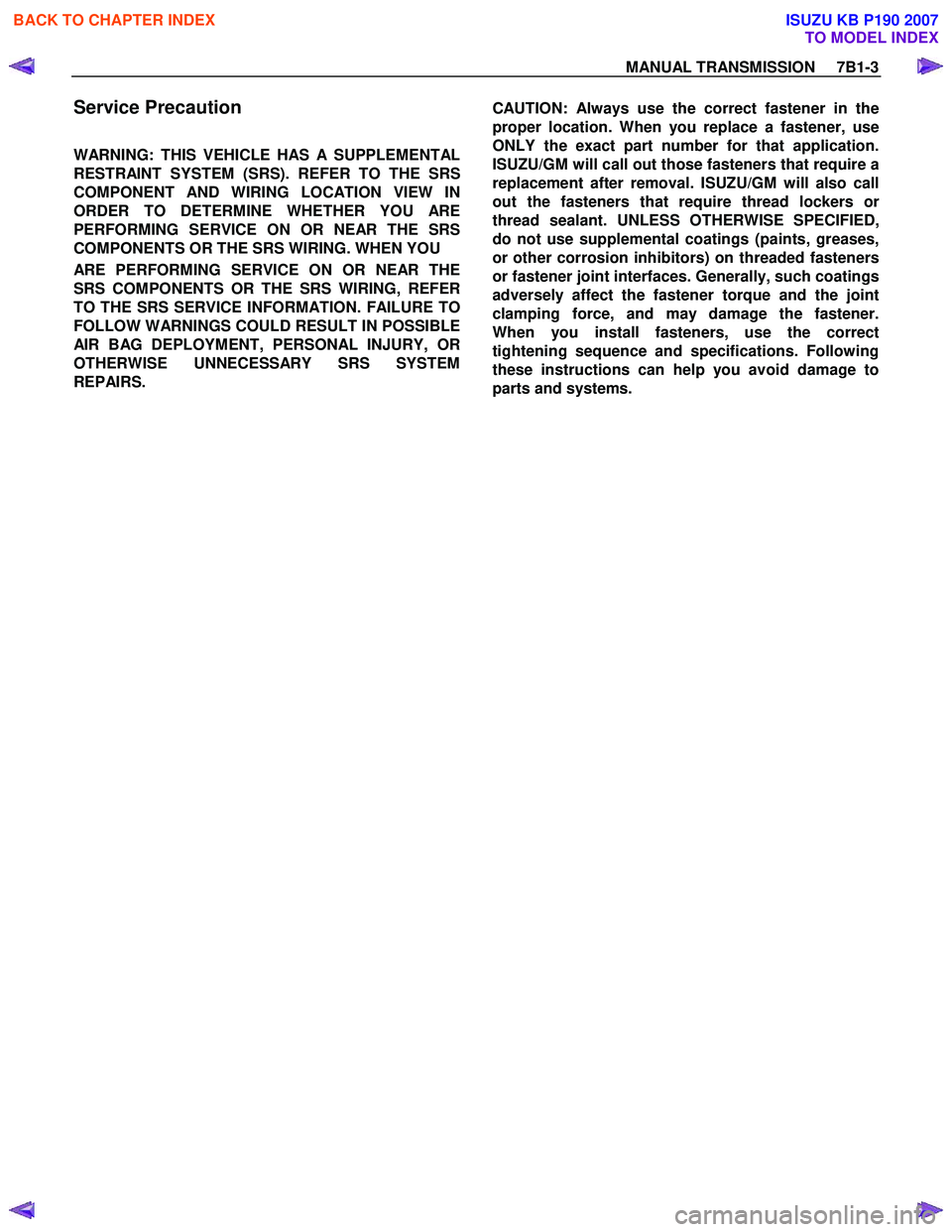
WARNING: THIS VEHICLE HAS A SUPPLEMENTAL
RESTRAINT SYSTEM (SRS). REFER TO THE SRS
COMPONENT AND WIRING LOCATION VIEW IN
ORDER TO DETERMINE WHETHER YOU ARE
PERFORMING SERVICE ON OR NEAR THE SRS
COMPONENTS OR THE SRS WIRING. WHEN YOU
ARE PERFORMING SERVICE ON OR NEAR THE
SRS COMPONENTS OR THE SRS WIRING, REFER
TO THE SRS SERVICE INFORMATION. FAILURE TO
FOLLOW WARNINGS COULD RESULT IN POSSIBLE
AIR BAG DEPLOYMENT, PERSONAL INJURY, OR
OTHERWISE UNNECESSARY SRS SYSTEM
REPAIRS.
CAUTION: Always use the correct fastener in the
proper location. When you replace a fastener, use
ONLY the exact part number for that application.
ISUZU/GM will call out those fasteners that require a
replacement after removal. ISUZU/GM will also call
out the fasteners that require thread lockers o
r
thread sealant. UNLESS OTHERWISE SPECIFIED,
do not use supplemental coatings (paints, greases,
or other corrosion inhibitors) on threaded fasteners
or fastener joint interfaces. Generally, such coatings
adversely affect the fastener torque and the joint
clamping force, and may damage the fastener.
When you install fasteners, use the correct
tightening sequence and specifications. Following
these instructions can help you avoid damage to
parts and systems.
BACK TO CHAPTER INDEX
TO MODEL INDEX
ISUZU KB P190 2007
Page 4665 of 6020
MANUAL TRANSMISSION 7B1-59
Service Precaution
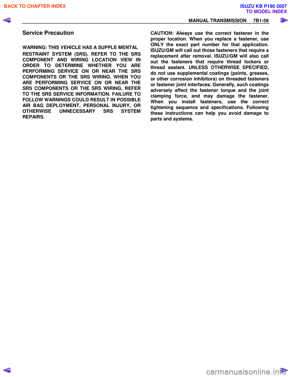
WARNING: THIS VEHICLE HAS A SUPPLE MENTAL
RESTRAINT SYSTEM (SRS). REFER TO THE SRS
COMPONENT AND WIRING LOCATION VIEW IN
ORDER TO DETERMINE WHETHER YOU ARE
PERFORMING SERVICE ON OR NEAR THE SRS
COMPONENTS OR THE SRS WIRING. WHEN YOU
ARE PERFORMING SERVICE ON OR NEAR THE
SRS COMPONENTS OR THE SRS WIRING, REFER
TO THE SRS SERVICE INFORMATION. FAILURE TO
FOLLOW WARNINGS COULD RESULT IN POSSIBLE
AIR BAG DEPLOYMENT, PERSONAL INJURY, OR
OTHERWISE UNNECESSARY SRS SYSTEM
REPAIRS.
CAUTION: Always use the correct fastener in the
proper location. When you replace a fastener, use
ONLY the exact part number for that application.
ISUZU/GM will call out those fasteners that require a
replacement after removal. ISUZU/GM will also call
out the fasteners that require thread lockers o
r
thread sealant. UNLESS OTHERWISE SPECIFIED,
do not use supplemental coatings (paints, greases,
or other corrosion inhibitors) on threaded fasteners
or fastener joint interfaces. Generally, such coatings
adversely affect the fastener torque and the joint
clamping force, and may damage the fastener.
When you install fasteners, use the correct
tightening sequence and specifications. Following
these instructions can help you avoid damage to
parts and systems.
BACK TO CHAPTER INDEX
TO MODEL INDEX
ISUZU KB P190 2007
Page 4832 of 6020
7D-2 TRANSFER CASE
Service Precaution
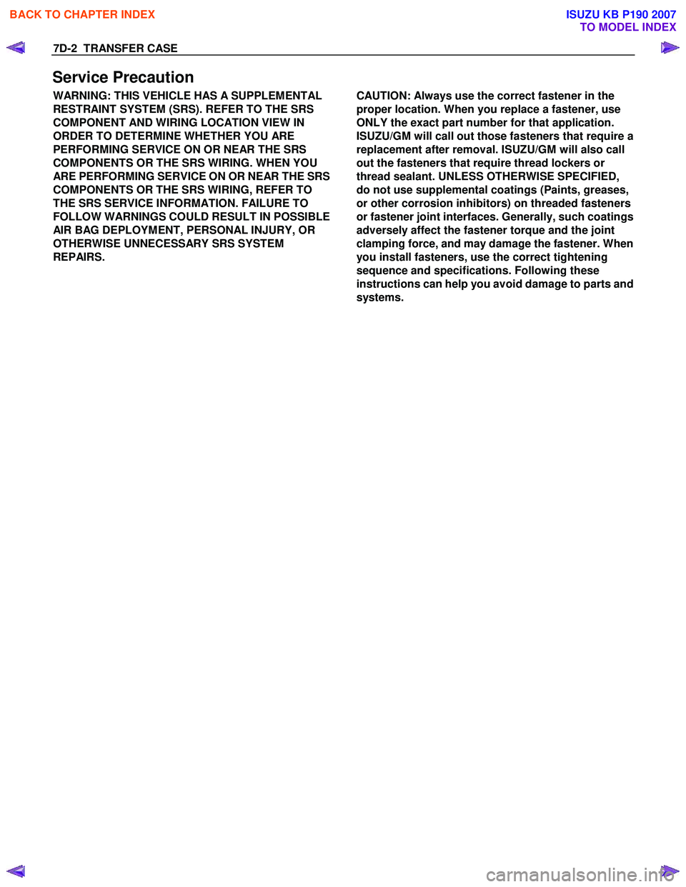
WARNING: THIS VEHICLE HAS A SUPPLEMENTAL
RESTRAINT SYSTEM (SRS). REFER TO THE SRS
COMPONENT AND WIRING LOCATION VIEW IN
ORDER TO DETERMINE WHETHER YOU ARE
PERFORMING SERVICE ON OR NEAR THE SRS
COMPONENTS OR THE SRS WIRING. WHEN YOU
ARE PERFORMING SERVICE ON OR NEAR THE SRS
COMPONENTS OR THE SRS WIRING, REFER TO
THE SRS SERVICE INFORMATION. FAILURE TO
FOLLOW WARNINGS COULD RESULT IN POSSIBLE
AIR BAG DEPLOYMENT, PERSONAL INJURY, OR
OTHERWISE UNNECESSARY SRS SYSTEM
REPAIRS.
CAUTION: Always use the correct fastener in the
proper location. When you replace a fastener, use
ONLY the exact part number for that application.
ISUZU/GM will call out those fasteners that require a
replacement after removal. ISUZU/GM will also call
out the fasteners that require thread lockers or
thread sealant. UNLESS OTHERWISE SPECIFIED,
do not use supplemental coatings (Paints, greases,
or other corrosion inhibitors) on threaded fasteners
or fastener joint interfaces. Generally, such coatings
adversely affect the fastener torque and the joint
clamping force, and may damage the fastener. When
you install fasteners, use the correct tightening
sequence and specifications. Following these
instructions can help you avoid damage to parts and
systems.
BACK TO CHAPTER INDEX
TO MODEL INDEX
ISUZU KB P190 2007
Page 4876 of 6020
7D1-2 TRANSFER CONTROL SYSTEM
Service Precaution
WARNING:
THIS VEHICLE HAS A SUPPLEMENTAL RESTRAINT
SYSTEM (SRS). REFER TO THE SRS COMPONENT AND
WIRING LOCATION VIEW IN ORDER TO DETERMINE
WHETHER YOU ARE PERFORMING SERVICE ON OR
NEAR THE SRS COMPONENTS OR THE SRS WIRING.
WHEN YOU ARE PERFORMING SERVICE ON OR NEAR
THE SRS COMPONENTS OR THE SRS WIRING, REFER TO
THE SRS SERVICE INFORMATION. FAILURE TO FOLLOW
WARNINGS COULD RESULT IN POSSIBLE AIR BAG
DEPLOYMENT, PERSONAL INJURY, OR OTHERWISE
UNNECESSARY SRS SYSTEM REPAIRS.
CAUTION:
Always use the correct fastener in the proper location.
When you replace a fastener, use ONLY the exact part
number for that application. ISUZU/GM will call out those
fasteners that require a replacement after removal.
ISUZU/GM will also call out the fasteners that require
thread lockers or thread sealant. UNLESS OTHERWISE
SPECIFIED, do not use supplemental coatings (Paints,
greases, or other corrosion inhibitors) on threaded
fasteners or fastener joint interfaces. Generally, such
coatings adversely affect the fastener torque and the joint
clamping force, and may damage the fastener. When you
install fasteners, use the correct tightening sequence and
specifications. Following these instructions can help you
avoid damage to parts and systems.
BACK TO CHAPTER INDEX
TO MODEL INDEX
ISUZU KB P190 2007
Page 4881 of 6020
TRANSFER CONTROL SYSTEM 7D1-7
7B4-PDF3
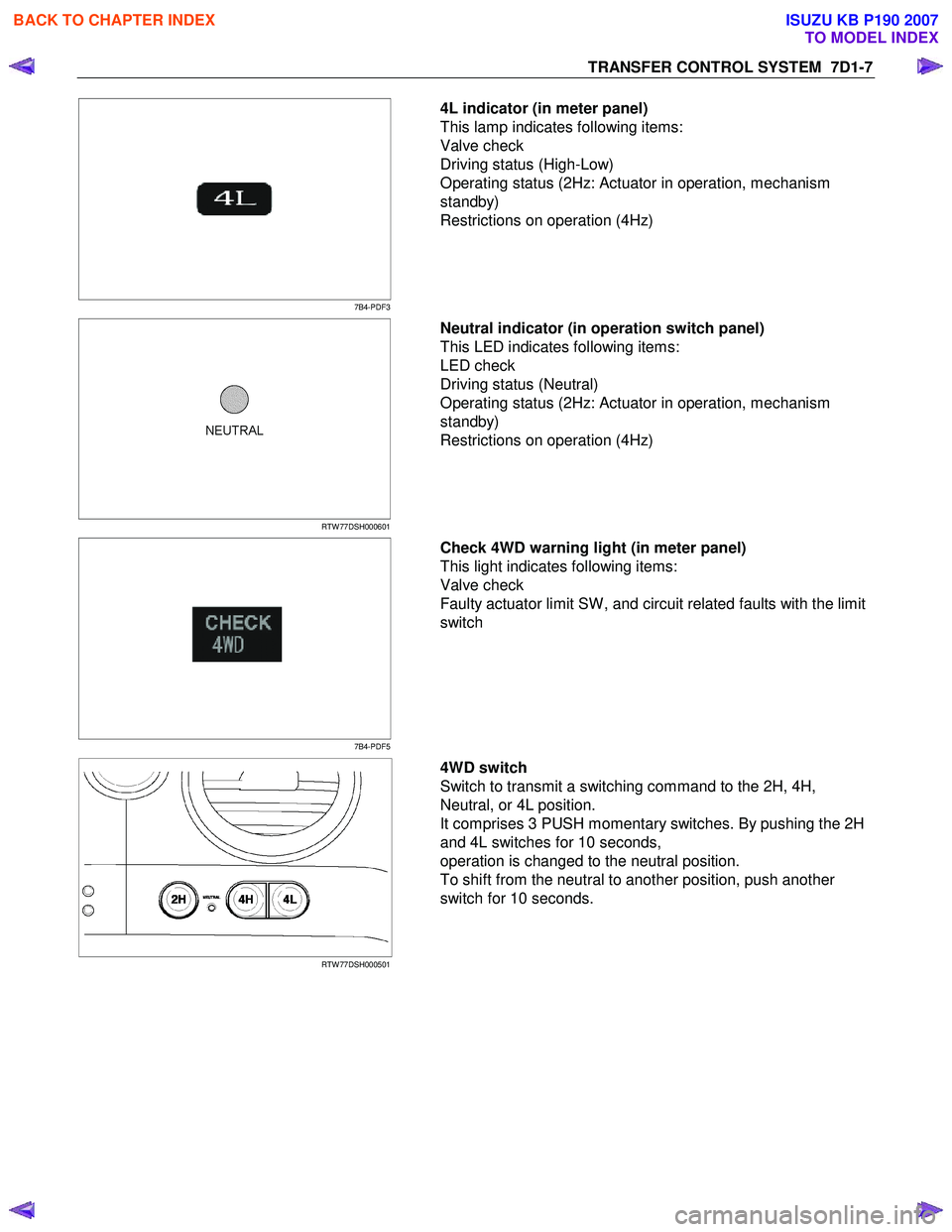
4L indicator (in meter panel)
This lamp indicates following items:
Valve check
Driving status (High-Low)
Operating status (2Hz: Actuator in operation, mechanism
standby)
Restrictions on operation (4Hz)
RTW 77DSH000601
Neutral indicator (in operation switch panel)
This LED indicates following items:
LED check
Driving status (Neutral)
Operating status (2Hz: Actuator in operation, mechanism
standby)
Restrictions on operation (4Hz)
7B4-PDF5
Check 4WD warning light (in meter panel)
This light indicates following items:
Valve check
Faulty actuator limit SW , and circuit related faults with the limit
switch
RTW 77DSH000501
4WD switch
Switch to transmit a switching command to the 2H, 4H,
Neutral, or 4L position.
It comprises 3 PUSH momentary switches. By pushing the 2H
and 4L switches for 10 seconds,
operation is changed to the neutral position.
To shift from the neutral to another position, push another
switch for 10 seconds.
BACK TO CHAPTER INDEX
TO MODEL INDEX
ISUZU KB P190 2007
Page 4886 of 6020

7D1-12 TRANSFER CONTROL SYSTEM
Functions of Switch and indicator Lamp
Transfer-related indicator lamp and switch function
Item 4WD
lamp 4L lamp Neutral
lamp Check
4WD
warning light 4WD
switch Actu ato r
detection (limit)
switches
LS1, LS2, LS3. and LS4
1 = on
2 = off Transfer
4WD
switch Transfer
neutral switch SOF
actuator switch Or
Axl e
dummy Remarks
2H Off Off Off Off No
operation 1,0,1,0 Open Open Open -----
4H start
of
operation Off Off Off Off 4H position
for 0.1
second 1,0,1,0 Open Open Open Switch
operation sensor
Start of
operation Blinking
(2HZ) Off Off Off No
operation 1,1,1,0
0,0,1,0
0,1,1,0
0,1,1,1 Open Open Open
2H to 4H
while
driving
During
operation
(Synchro) Blinking
(2HZ) Off Off Off No
operation 1,1,1,0
0,0,1,0
0,1,1,0
0,1,1,1 Open Open Open 2H to 4H
using
synchro and
retrial
During
operation (Axle
drive) Blinking
(2HZ) Off Off Off No
operation 0,0,1,1 Closed Open Open Axle drive
Axle
waiting Blinking
(2HZ) Off Off Off No
operation 0,0,1,1 Closed Open Open Axle drive
4H On Off Off Off No
operation 0,0,1,1 Closed Open Closed -----
4L start
of
operation On Off Off Off 4L position
for 0.1
second 0,0,1,1 Closed Open Closed Switch
operation sensor
Start of
operation On Blinking
(2HZ) Off Off No
operation 0,0,0,1
0,1,0,1 Closed Open Closed 4H to 4L
while
driving
During
operation (N) Off
Blinking
(2HZ) Off Off No
operation 0,0,0,1
0,1,0,1 Closed Closed Closed 4H to 4L
through neutral
During
operation (N) Off
Blinking
(2HZ) Off Off No
operation 0,1,0,0 Closed Closed Closed 4H to 4L
through neutral
During
operation (N) Off
Blinking
(2HZ) Off Off No
operation 1,1,0,0 Closed Closed Closed 4H to 4L
through neutral
4L
waiting On Blinking
(2HZ) Off Off No
operation 1,1,0,1 Closed Closed Closed 4H to 4L
while
waiting
4L On On Off Off No
operation 1,1,0,1 Closed Open Closed -----
4H start of
operation On Off Off Off 4H position
for 0.1
second 1,1,0,1 Closed Open Closed Switch
operation sensor
BACK TO CHAPTER INDEX
TO MODEL INDEX
ISUZU KB P190 2007
Page 4887 of 6020
TRANSFER CONTROL SYSTEM 7D1-13
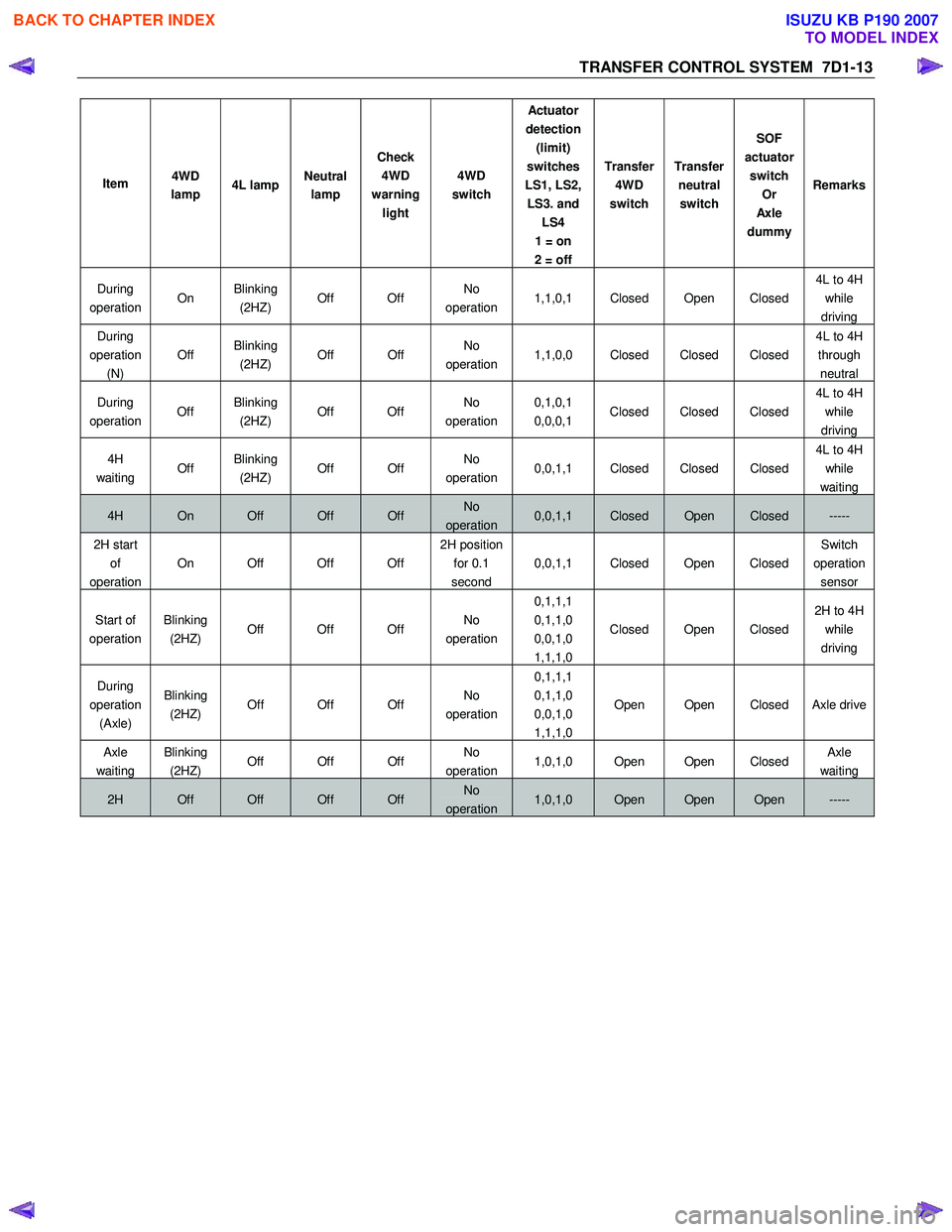
Item 4WD
lamp 4L lamp Neutral
lamp Check
4WD
warning light 4WD
switch Actu ato r
detection (limit)
switches
LS1, LS2, LS3. and LS4
1 = on
2 = off Transfer
4WD
switch Transfer
neutral switch SOF
actuator switch Or
Axl e
dummy Remarks
During
operation On Blinking
(2HZ) Off Off No
operation 1,1,0,1 Closed Open Closed 4L to 4H
while
driving
During
operation (N) Off
Blinking
(2HZ) Off Off No
operation 1,1,0,0 Closed Closed Closed 4L to 4H
through neutral
During
operation Off Blinking
(2HZ) Off Off No
operation 0,1,0,1
0,0,0,1 Closed Closed Closed 4L to 4H
while
driving
4H
waiting Off Blinking
(2HZ) Off Off No
operation 0,0,1,1 Closed Closed Closed
4L to 4H
while
waiting
4H On Off Off Off No
operation 0,0,1,1 Closed Open Closed -----
2H start of
operation On Off Off Off 2H position
for 0.1
second 0,0,1,1 Closed Open Closed Switch
operation sensor
Start of
operation Blinking
(2HZ) Off Off Off No
operation 0,1,1,1
0,1,1,0
0,0,1,0
1,1,1,0 Closed Open Closed
2H to 4H
while
driving
During
operation (Axle) Blinking
(2HZ) Off Off Off No
operation 0,1,1,1
0,1,1,0
0,0,1,0
1,1,1,0 Open Open Closed Axle drive
Axle
waiting
Blinking
(2HZ) Off Off Off No
operation 1,0,1,0 Open Open Closed Axle
waiting
2H Off Off Off Off No
operation 1,0,1,0 Open Open Open -----
BACK TO CHAPTER INDEX
TO MODEL INDEX
ISUZU KB P190 2007