2007 ISUZU KB P190 Fuel line
[x] Cancel search: Fuel linePage 2443 of 6020
ENGINE DRIVEABILITY AND EMISSIONS 6E–273
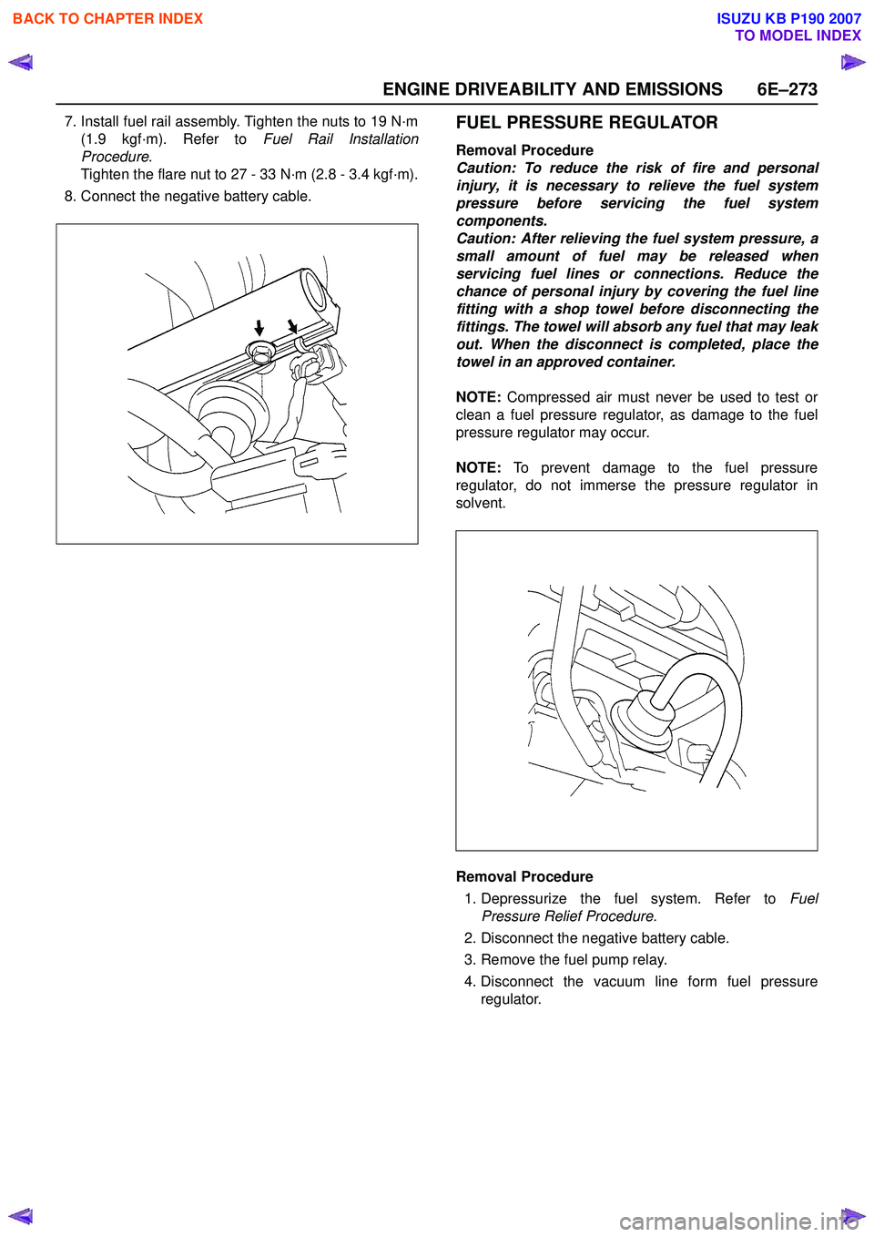
7. Install fuel rail assembly. Tighten the nuts to 19 N·m(1.9 kgf·m). Refer to Fuel Rail Installation
Procedure .
Tighten the flare nut to 27 - 33 N·m (2.8 - 3.4 kgf·m).
8. Connect the negative battery cable.FUEL PRESSURE REGULATOR
Removal Procedure
Caution: To reduce the risk of fire and personal
injury, it is necessary to relieve the fuel system
pressure before servicing the fuel system
components.
Caution: After relieving the fuel system pressure, a
small amount of fuel may be released when
servicing fuel lines or connections. Reduce the
chance of personal injury by covering the fuel line
fitting with a shop towel before disconnecting the
fittings. The towel will absorb any fuel that may leak
out. When the disconnect is completed, place the
towel in an approved container.
NOTE: Compressed air must never be used to test or
clean a fuel pressure regulator, as damage to the fuel
pressure regulator may occur.
NOTE: To prevent damage to the fuel pressure
regulator, do not immerse the pressure regulator in
solvent.
Removal Procedure
1. Depressurize the fuel system. Refer to Fuel
Pressure Relief Procedure.
2. Disconnect the negative battery cable.
3. Remove the fuel pump relay.
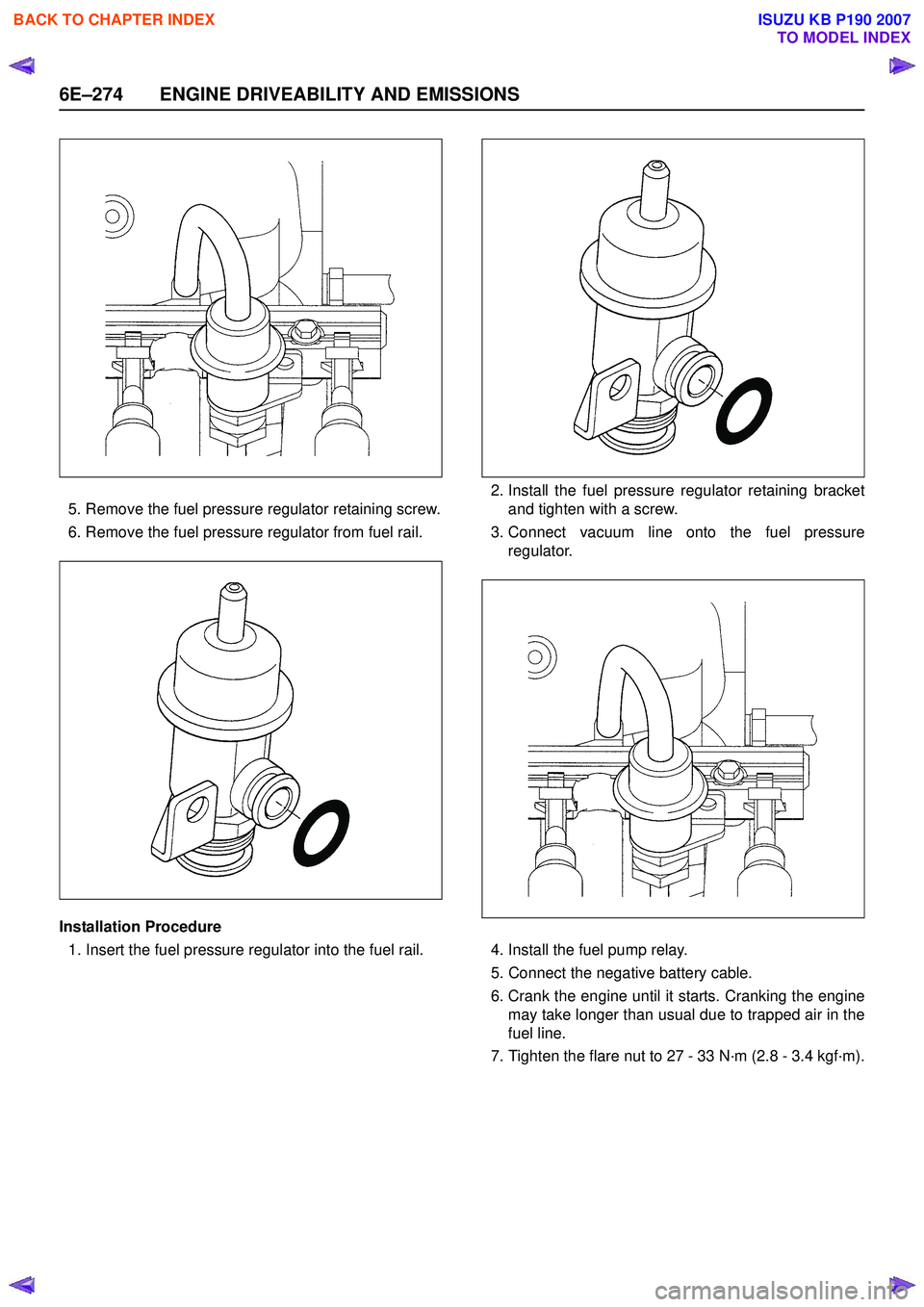
4. Disconnect the vacuum line form fuel pressure regulator.
BACK TO CHAPTER INDEX
TO MODEL INDEX
ISUZU KB P190 2007
Page 2444 of 6020
6E–274 ENGINE DRIVEABILITY AND EMISSIONS
5. Remove the fuel pressure regulator retaining screw.
6. Remove the fuel pressure regulator from fuel rail.
Installation Procedure 1. Insert the fuel pressure regulator into the fuel rail. 2. Install the fuel pressure regulator retaining bracket
and tighten with a screw.
3. Connect vacuum line onto the fuel pressure regulator.
4. Install the fuel pump relay.
5. Connect the negative battery cable.
6. Crank the engine until it starts. Cranking the engine may take longer than usual due to trapped air in the
fuel line.
7. Tighten the flare nut to 27 - 33 N·m (2.8 - 3.4 kgf·m).
BACK TO CHAPTER INDEX
TO MODEL INDEX
ISUZU KB P190 2007
Page 2517 of 6020
Engine Mechanical – V6 Page 6A1–38
2.15 Engine Compression Test
A compression pressure test of the engine cylinders determines the condition of the rings, the valves and the head
gasket.
Preliminary Steps
1 Ensure the battery is fully charged.
2 Remove the spark plugs from all cylinders, refer to 6C1-3 Engine Management – V6 – Service Operations.
NOTE
DTCs will set when the fuel system or the ignition
system is disabled and the engine is cranked.
Disregard DTCs that set under this condition.
3 Disable the fuel system by removing the fuel pump relay, refer to 8A Electrical Body & Chassis.
4 Start the engine to use any residual fuel from the fuel lines.
4 Disable the ignition coils by removing fuses 34 and 35, refer to 8A Electrical Body & Chassis .
5 Using Tech 2, command the throttle plate to wide open throttle.
Engine Cylinder Compression Test
1 Install the compression tester to cylinder number 1.
2 W hile observing the compression tester reading, turn the ignition to the START position for several seconds and then allow the ignition to return to the ON position.
3 Record the highest compression reading obtained.
4 Repeat the engine compression test for each cylinder.
Test Result Evaluation
Normal engine compression pressure builds quickly and evenly to over 965 kPa. In addition, the lowest reading of an
engine cylinder should not be less than 70 percent of the highest reading. If any cylinder fails the compression test,
adding 15 ml of engine oil to the suspected cylinder may help isolate the following fault condition.
1 A fault condition in the piston rings will produce the following result:
• A low compression on the first engine cycle
• The compression tends to build-up with the succeeding engine rotation.
• The compression improves with the addition of engine oil.
2 A fault condition in an intake or exhaust valve will produce the following result:
• A low compression on the first engine cycle
• The compression does not build with the succeeding engine rotation.
• The compression does not improve with the addition of engine oil.
3 A fault condition in the cylinder head gasket will produce the following result:
• A low compression on the first engine cycle
• The compression does not build with the succeeding engine rotation.
• The compression does not improve with the addition of engine oil.
• The suspected cylinders are positioned adjacent to each other.
• The engine oil may be contaminated with engine coolant.
• The engine coolant may be contaminated with engine oil.
Once the fault has been identified, refer to the relevant service procedure and reinstall the removed components.
Using Tech 2, clear DTCs.
BACK TO CHAPTER INDEX
TO MODEL INDEX
ISUZU KB P190 2007
Page 2552 of 6020
Engine Mechanical – V6 Page 6A1–73
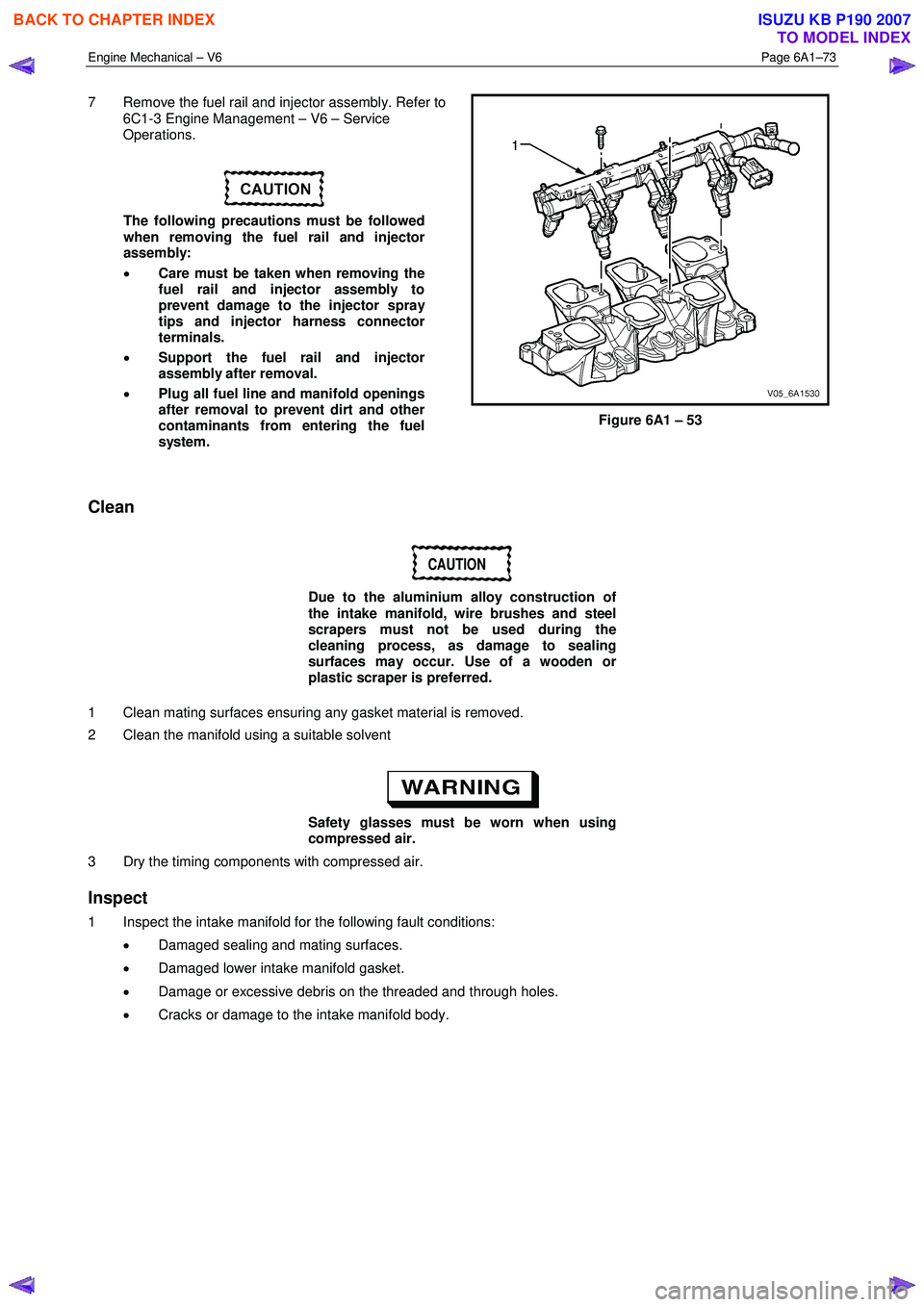
7 Remove the fuel rail and injector assembly. Refer to
6C1-3 Engine Management – V6 – Service
Operations.
The following precautions must be followed
when removing the fuel rail and injector
assembly:
• Care must be taken when removing the
fuel rail and injector assembly to
prevent damage to the injector spray
tips and injector harness connector
terminals.
• Support the fuel rail and injector
assembly after removal.
• Plug all fuel line and manifold openings
after removal to prevent dirt and other
contaminants from entering the fuel
system.
Figure 6A1 – 53
Clean
CAUTION
Due to the aluminium alloy construction of
the intake manifold, wire brushes and steel
scrapers must not be used during the
cleaning process, as damage to sealing
surfaces may occur. Use of a wooden or
plastic scraper is preferred.
1 Clean mating surfaces ensuring any gasket material is removed.
2 Clean the manifold using a suitable solvent
Safety glasses must be worn when using
compressed air.
3 Dry the timing components with compressed air.
Inspect
1 Inspect the intake manifold for the following fault conditions:
• Damaged sealing and mating surfaces.
• Damaged lower intake manifold gasket.
• Damage or excessive debris on the threaded and through holes.
• Cracks or damage to the intake manifold body.
BACK TO CHAPTER INDEX
TO MODEL INDEX
ISUZU KB P190 2007
Page 2677 of 6020
Engine Mechanical – V6 Page 6A1–198
k Timing chains, tensioners, shoes, guides & sprockets, refer to 3.16 Timing Chains, Tensioners, Shoes and
Guides.
l Cylinder head assemblies, refer to 3.22 Cylinder Head Assembly.
m Oil pan assembly, refer to 4.2 Oil Pan and Oil Pump Suction Pipe Assembly.
n Piston and connecting rod assemblies, refer to 4.5 Pistons, Pins, Rings, Connecting Rods and Big-end Bearings.
o Crankshaft assembly, refer to 4.6 Crankshaft and Main Bearings.
p Piston oil nozzles, refer 4.5 Pistons, Pins, Rings, Connecting Rods and Big-end Bearings.
Reassemble
Reassembly of the engine assembly is the reverse of the disassembly procedure.
Reinstall
Reinstallation of the engine assembly is the reverse to the removal procedure, noting the following:
NOTE
Refer to 6 Torque Wrench Specifications
for the correct torque specifications.
1 Tighten the fasteners to the correct torque specification.
Engine ground connector bolt
torque specification ............................................10.0 Nm
Power steering high pressure line
attaching bolt torque specification .............8.0 – 12.0 Nm
Power steering high pressure line
flare nut torque specification ...................25.0 – 35.0 Nm
Engine mount to frame attaching bolt
torque specification .................................44.0 – 60.0 Nm
Knock Sensor Attaching Nut
torque specification ............................................23.0 Nm
2 Use only the specified engine lubricant type and quantity. It is recommended that a fluorescent oil dye, such as that contained in J 28481-B, be added to assist in any future oil leak diagnosis.
3 Fill the cooling system with the correct quantity and grade of coolant, refer to 6B1 Engine Cooling – V6.
4 Check transmission fluid level, replenishing as required, using the specified lubricant for the transmission fitted, refer to 7C1 Automatic – 4L60E – General Information.
5 Disable the ignition system, refer to 6C1-3 Engine Management – V6 – Service Operations.
6 Crank the engine several times. Listen for any unusual noises or evidence that parts are binding.
7 Enable the ignition system. Start the engine and listen for any unusual noises.
8 Check the vehicle oil pressure gauge or warning indicator and confirm the engine has acceptable oil pressure. If required, install an oil pressure gauge and measure the engine oil pressure, refer to 2.19 Engine Oil Pressure
Diagnosis.
9 Run the engine at about 1,000 r.p.m. until the engine has reached normal operating temperature.
10 Listen for any unusual noises.
11 Check for oil, fuel, coolant and exhaust leaks while the engine is running, correcting as required.
12 Perform a final inspection for correct engine oil and coolant levels.
4.2 Oil Pan and Oil Pump Suction Pipe Assembly
Remove
1 Remove the engine assembly from the vehicle, refer to 4.1 Engine .
2 Separate the engine and transmission assemblies, refer to 7C1 Automatic – 4L60E – General Information.
3 Mount the engine assembly on a suitable engine stand.
4 Remove the engine front cover, refer to 3.15 Front Cover Assembly.
BACK TO CHAPTER INDEX
TO MODEL INDEX
ISUZU KB P190 2007
Page 2822 of 6020
Engine Mechanical – V6 Page 6A1–45
Page 6A1–45
2.15 Engine Compression Test
A compression pressure test of the engine cylinders determines the condition of the rings, the valves and the head
gasket.
Preliminary Steps
1 Ensure the battery is fully charged.
2 Remove the spark plugs from all cylinders, refer to Section 6C1-3 Engine Management – V6 – Service Operations.
NOTE
DTCs will set when the fuel system or the ignition
system is disabled and the engine is cranked.
Disregard DTCs that set under this condition.
3 Disable the fuel system by removi ng the fuel pump relay, refer to Section 8A Electrical Body & Chassis .
4 Start the engine to use any resi dual fuel from the fuel lines.
4 Disable the ignition coils by removing fuses 34 and 35, refer to Section 8A Electrical Body & Chassis .
5 Using Tech 2, command the throttle plate to wide open throttle.
Engine Cylinder Compression Test
1 Install the compression tester to cylinder number 1.
2 While observing the compression tester reading, turn t he ignition to the START position for several seconds and
then allow the ignition to return to the ON position.
3 Record the highest compression reading obtained.
4 Repeat the engine compression test for each cylinder.
Test Result Evaluation
Normal engine compression pressure builds quickly and evenly to over 965 kPa. In addition, the lowest reading of an
engine cylinder should not be less than 70 per cent of the highest reading. If any cylinder fails the compression test,
adding 15 ml of engine oil to the suspected cylinder may help isolate the following fault condition.
1 A fault condition in the piston rings will produce the following result:
• A low compression on the first engine cycle
• The compression tends to build-up with the succeeding engine rotation.
• The compression improves with the addition of engine oil.
2 A fault condition in an intake or exhaus t valve will produce the following result:
• A low compression on the first engine cycle
• The compression does not build with the succeeding engine rotation.
• The compression does not improve with the addition of engine oil.
3 A fault condition in the cylinder head gasket will produce the following result:
• A low compression on the first engine cycle
• The compression does not build with the succeeding engine rotation.
• The compression does not improve with the addition of engine oil.
• The suspected cylinders are pos itioned adjacent to each other.
• The engine oil may be contaminated with engine coolant.
• The engine coolant may be cont aminated with engine oil.
Once the fault has been identified, refe r to the relevant service procedure and reinstall the removed components.
Using Tech 2, clear DTCs.
BACK TO CHAPTER INDEX
TO MODEL INDEX
ISUZU KB P190 2007
Page 2864 of 6020

Engine Mechanical – V6 Page 6A1–87
Page 6A1–87
When the intake manifold is removed, plug
each of the cylinder head intake openings
with lint free cloth, to stop the entry of foreign
material into the intake ports.
21 Remove the upper and lower intake manifold assembly from the engine.
22 Remove lower intake mani fold to cylinder head gasket.
Disassemble
1 Disconnect the EVAP hose (1) from the upper intake
manifold (2).
2 Remove the bolts (3) (70 mm long) attaching the upper intake manifold to the lower intake manifold (4).
NOTE
These bolts are located at the front left and rear
right of the upper intake manifold, as shown.
3 Remove the upper intake manifold from the lower intake manifold.
4 Remove and discard the upper to lower intake manifold gaskets.
Do not reuse the upper to lower intake
manifold gaskets (5).
5 Remove the EVAP hose from the retaining clip (6) attached to the lower intake manifold.
6 Remove the following from the upper intake manifold, refer to Section 6C1-3 Engine Management – V6 –
Service Operations :
• BARO Sensor and
• Throttle Body assembly
Figure 6A1 – 52
7 Remove the fuel rail and in jector assembly. Refer to
Section 6C1-3 Engine Management – V6 – Service
Operations .
The following precautions must be followed
when removing the fuel rail and injector
assembly:
• Care must be taken when removing the
fuel rail and injector assembly to
prevent damage to the injector spray
tips and injector harness connector
terminals.
• Support the fuel rail and injector
assembly after removal.
• Plug all fuel line and manifold openings
after removal to prevent dirt and other
contaminants from entering the fuel
system.
Figure 6A1 – 53
BACK TO CHAPTER INDEX
TO MODEL INDEX
ISUZU KB P190 2007
Page 3030 of 6020
Engine Mechanical – V6 Page 6A1–253
Page 6A1–253
k Timing chains, tensioners, shoes, guides & sprockets, refer to 3.16 Timing Chains, Tensioners, Shoes and
Guides .
l Cylinder head assemblies, refer to 3.22 Cylinder Head Assembly.
m Oil pan assembly, refer to 4.2 Oil Pan and Oil Pump Suction Pipe Assembly .
n Piston and connecting rod assemblies, refer to 4.5 Pistons, Pins, Rings, Connecting Rods and Big-end
Bearings .
o Crankshaft assembly, refer to 4.6 Crankshaft and Main Bearings.
p Piston oil nozzles, refer 4.5 Pistons, Pins, Rings, Connecting Rods and Big-end Bearings .
Reassemble
Reassembly of the engine assembly is the reverse of the disassembly procedure.
Reinstall
Reinstallation of the engine assembly is the revers e to the removal procedure, noting the following:
NOTE
Refer to 6 Torque Wrench Specifications for the
correct torque specifications.
1 Tighten the fasteners to the co rrect torque specification.
Engine ground connector bolt
torque specificat ion ............................................ 10.0 Nm
Power steering high pressure line
attaching bolt torque specification ............. 8.0 – 12.0 Nm
Power steering high pressure line
flare nut torque specif ication ................... 25. 0 – 35.0 Nm
Engine mount to frame attaching bolt
torque specification ................................. 44. 0 – 60.0 Nm
Knock Sensor Attaching Nut
torque specification ............................................ 23.0 Nm
2 Use only the specified engine lubricant type and quantity. It is recommended that a fluorescent oil dye, such as that
contained in J 28481-B, be added to assist in any future oil leak diagnosis.
3 Fill the cooling system with the corre ct quantity and grade of coolant, refer to Section 6B1 Engine Cooling – V6.
4 Check transmission fluid level, replenishing as required, using the specified lubricant for the transmission fitted,
refer to Section 7C1 Automatic – 4L60E – General Information .
5 Disable the ignition system, refer to Section 6C1-3 Engine Management – V6 – Service Operations.
6 Crank the engine several times. Listen for any unusual noises or evidence that parts are binding.
7 Enable the ignition system. Start t he engine and listen for any unusual noises.
8 Check the vehicle oil pressure gauge or warning indica tor and confirm the engine has acceptable oil pressure. If
required, install an oil pressure gauge and m easure the engine oil pressure, refer to 2.19 Engine Oil Pressure
Diagnosis .
9 Run the engine at about 1,000 r. p.m. until the engine has reached normal operating temperature.
10 Listen for any unusual noises.
11 Check for oil, fuel, coolant and exhaust leaks wh ile the engine is running, correcting as required.
12 Perform a final inspection for correct engine oil and coolant levels.
BACK TO CHAPTER INDEX
TO MODEL INDEX
ISUZU KB P190 2007