2007 ISUZU KB P190 Fuel line
[x] Cancel search: Fuel linePage 1962 of 6020
ENGINE CONTROL SYSTEM (4JK1/4JJ1) 6E-345
Excessive Smoke (White Smoke)
ChecksAction
Difinition:
White smoke under load, idle or start up hot or cold.
Preliminary Check • Ensure the vehicle has an actual problem.
• Inspect the ECM grounds for being clean, tight, and in their proper locations.
• Inspect the fuel quality (cetane index).
• Inspect the programmed fuel injector ID code for each cylinder.
• Inspect the Scan Tool Data List in this section.
• Inspect the Service Bulletin.
Sensor Checks Inspect the engine control sensors for the following conditions. Refer to the Scan Tool
Data List in this section.
• Compare the Coolant Temperature with the Intake Air Temperature (IAT) and Fuel Temperature (FT) parameters on a cold engine condition. If the difference among
temperature reading is more than 5 °C (9 °F) on a cold engine, check for high
resistance in each circuit or for a skewed sensor.
Notice: The mass air flow (MAF) sensor is heated and as a result the IAT may indicate
a higher than normal intake air temperature if the ignition switch is being ON.
• Observe the Fuel Rail Pressure (FRP) Sensor parameter with the engine OFF. The FRP Sensor should read 0.9 to 1.0 volt with the key ON and engine OFF after the
engine has stopped running for a minimum of 1 minute. If not, check for high
resistance in each circuit or for a skewed sensor.
• Observe the Fuel Rail Pressure and Desired Fuel Rail Pressure parameter between idle and W.O.T. (accelerator pedal full travel) in Neutral. Fuel Rail Pressure
parameter should follow within ± 5 MPa ( ± 725 psi) quick enough.
• Observe the Accelerator Pedal Position (APP). APP parameter should change linearly from 0 to 100% according to the accelerator pedal operation.
• Observe the Boost Pressure and Barometric Pressure (BARO) with ignition ON and engine OFF. Both parameters should be within the 7.0 kPa (1.0 psi) each other.
• Crankshaft position (CKP) sensor is tight and the sensor rotor is not damaged.
Fuel System Checks • If excessive smoke is present, check for a stuck open fuel injector. Inspect for fuel
leakage into the combustion chamber.
• Fuel injectors. Remove the injectors and visually inspect.
• Perform the Cylinder Balance Test with a scan tool.
• Perform the Pilot Injection Control with a scan tool.
• Observe the Fuel Compensation for each cylinder at idle on the scan tool.
Air Intake System Checks Inspect the air intake system for the following conditions.
• Air cleaner, air intake ducts and charge air cooler for a restriction, holes, or leaks.
• A restriction in the turbocharger inlet duct.
• Intake throttle valve for a stuck condition.
• A restriction or leak in the intake manifold.
• A restriction or damaged at MAF sensor.
• Perform the Swirl Control Solenoid Test with a scan tool. Inspect the diaphragm valve operation when it commanded ON/ OFF.
• A worn or damaged turbocharger turbine wheel, shaft or compressor wheel. Oil leak from turbocharger. Refer to turbocharger inspection in the Engine Mechanical
section.
BACK TO CHAPTER INDEX
TO MODEL INDEX
ISUZU KB P190 2007
Page 1965 of 6020
6E-348 ENGINE CONTROL SYSTEM (4JK1/4JJ1)
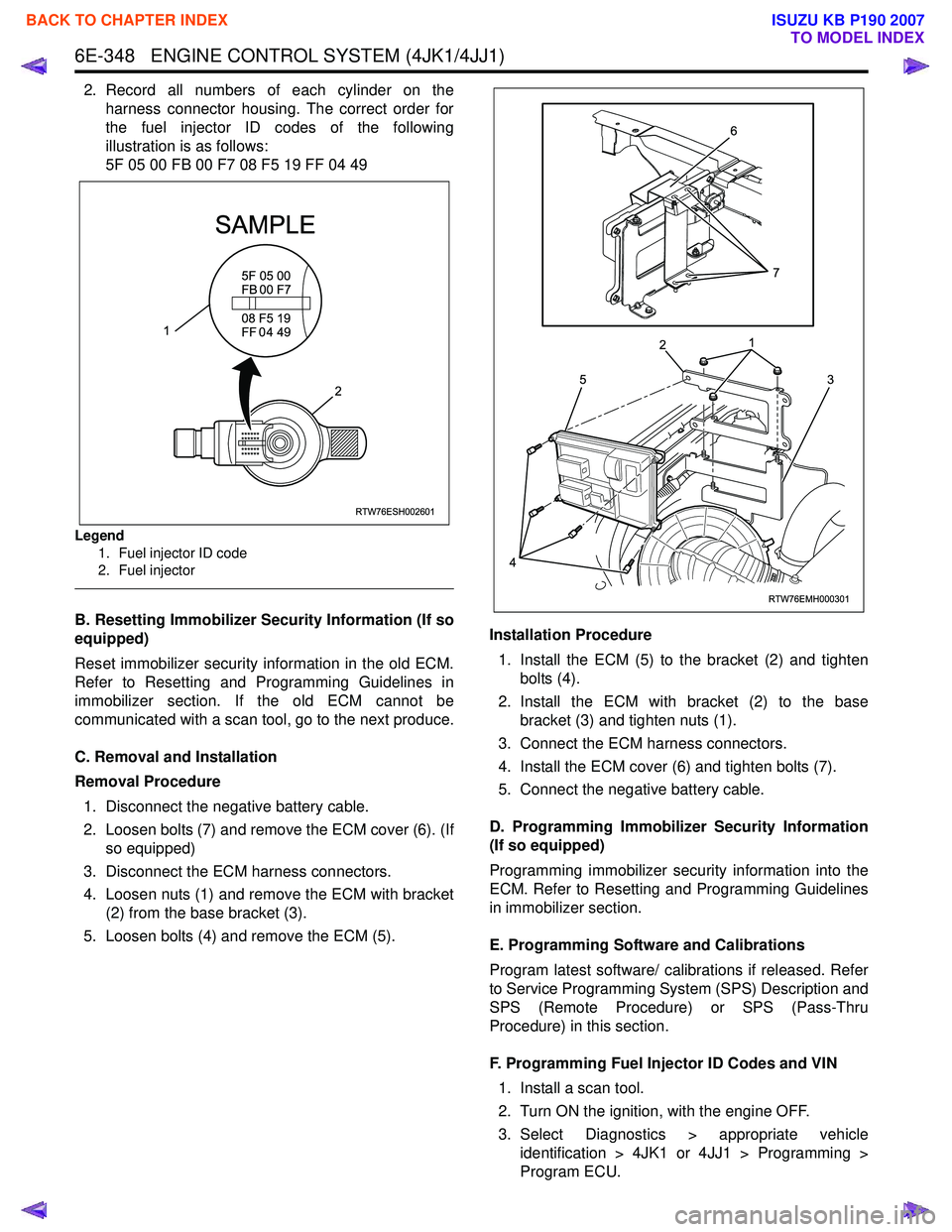
2. Record all numbers of each cylinder on theharness connector housing. The correct order for
the fuel injector ID codes of the following
illustration is as follows:
5F 05 00 FB 00 F7 08 F5 19 FF 04 49
Legend
1. Fuel injector ID code
2. Fuel injector
B. Resetting Immobilizer Security Information (If so
equipped)
Reset immobilizer security information in the old ECM.
Refer to Resetting and Programming Guidelines in
immobilizer section. If the old ECM cannot be
communicated with a scan tool, go to the next produce.
C. Removal and Installation
Removal Procedure 1. Disconnect the negative battery cable.
2. Loosen bolts (7) and remove the ECM cover (6). (If so equipped)
3. Disconnect the ECM harness connectors.
4. Loosen nuts (1) and remove the ECM with bracket (2) from the base bracket (3).
5. Loosen bolts (4) and remove the ECM (5). Installation Procedure
1. Install the ECM (5) to the bracket (2) and tighten bolts (4).
2. Install the ECM with bracket (2) to the base bracket (3) and tighten nuts (1).
3. Connect the ECM harness connectors.
4. Install the ECM cover (6) and tighten bolts (7).
5. Connect the negative battery cable.
D. Programming Immobilizer Security Information
(If so equipped)
Programming immobilizer security information into the
ECM. Refer to Resetting and Programming Guidelines
in immobilizer section.
E. Programming Software and Calibrations
Program latest software/ calibrations if released. Refer
to Service Programming System (SPS) Description and
SPS (Remote Procedure) or SPS (Pass-Thru
Procedure) in this section.
F. Programming Fuel Injector ID Codes and VIN 1. Install a scan tool.
2. Turn ON the ignition, with the engine OFF.
3. Select Diagnostics > appropriate vehicle identification > 4JK1 or 4JJ1 > Programming >
Program ECU.
RTW76ESH002601
5F 05 00
FB 00 F7
SAMPLE
08 F5 19
FF 0 4 49
2
1
RTW76EMH000301
5
1
2
3
4
6
7
BACK TO CHAPTER INDEX
TO MODEL INDEX
ISUZU KB P190 2007
Page 1971 of 6020
6E-354 ENGINE CONTROL SYSTEM (4JK1/4JJ1)
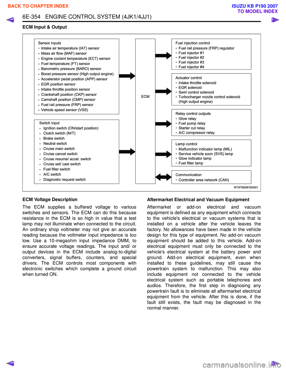
ECM Input & Output
ECM Voltage Description
The ECM supplies a buffered voltage to various
switches and sensors. The ECM can do this because
resistance in the ECM is so high in value that a test
lamp may not illuminate when connected to the circuit.
An ordinary shop voltmeter may not give an accurate
reading because the voltmeter input impedance is too
low. Use a 10-megaohm input impedance DMM, to
ensure accurate voltage readings. The input and/ or
output devices in the ECM include analog-to-digital
converters, signal buffers, counters, and special
drivers. The ECM controls most components with
electronic switches which complete a ground circuit
when turned ON. Aftermarket Electrical and Vacuum Equipment
Aftermarket or add-on electrical and vacuum
equipment is defined as any equipment which connects
to the vehicle's electrical or vacuum systems that is
installed on a vehicle after the vehicle leaves the
factory. No allowances have been made in the vehicle
design for this type of equipment. No add-on vacuum
equipment should be added to this vehicle. Add-on
electrical equipment must only be connected to the
vehicle's electrical system at the battery power and
ground. Add-on electrical equipment, even when
installed to these guidelines, may still cause the
powertrain system to malfunction. This may also
include equipment not connected to the vehicle
electrical system such as portable telephones and
audios. Therefore, the first step in diagnosing any
powertrain fault is to eliminate all aftermarket electrical
equipment from the vehicle. After this is done, if the
fault still exists, the fault may be diagnosed in the
normal manner.
RTW76EMF000501
Sensor inputs
· Intake air temperature (IAT) sensor
· Mass air flow (MAF) sensor
· Engine coolant temperature (ECT) sensor
· Fuel temperature (FT) sensor
· Barometric pressure (BARO) sensor
· Boost pressure sensor (High output engine)
· Accelerator pedal position (APP) sensor
· EGR position sensor
· Intake throttle position sensor
· Crankshaft position (CKP) sensor
· Camshaft position (CMP) sensor
· Fuel rail pressure (FRP) sensor
· Vehicle speed sensor (VSS)
Switch input
· Ignition switch (ON/start position)
· Clutch switch (M/T)
· Brake switch
· Neutral switch
· Cruise main switch
· Cruise cancel switch
· Cruise resume/ accel. switch
· Cruise set/ cast switch
· Fuel filter switch
· A/C switch
· Diagnostic request switch
Fuel injection control
· Fuel rail pressure (FRP) regulator
· Fuel injector #1
· Fuel injector #2
· Fuel injector #3
· Fuel injector #4
Relay control outputs
· Glow relay
· Fuel pump relay
· Starter cut relay
· A/C compressor relay
Lamp control
· Malfunction indicator lamp (MIL)
· Service vehicle soon (SVS) lamp
· Glow indicator lamp
· Fuel filter lamp
Communication
· Controller area network (CAN)
Actuator control
· Intake throttle solenoid
· EGR solenoid
· Swirl control solenoid
· Turbocharger nozzle control solenoid
(High output engine)ECM
BACK TO CHAPTER INDEX
TO MODEL INDEX
ISUZU KB P190 2007
Page 1980 of 6020
ENGINE CONTROL SYSTEM (4JK1/4JJ1) 6E-363
Along with the employment of a common rail type
electronic control fuel injection system, the fuel rail is
provided to store high pressure fuel between supply
pump and injectors. A pressure sensor and a pressure
limiter are installed on the fuel rail. The pressure sensor
detects the fuel pressure inside the fuel rail and sends
its signal to the ECM. Based on this signal, the ECM
controls the fuel pressure inside the fuel rail via the fuel
rail pressure (FRP) regulator of the supply pump. The
pressure limiter opens the valve mechanically to relieve
the pressure when the fuel pressure inside the fuel rail
is excessive.
Fuel Rail Pressure Sensor
The FRP sensor is installed to the fuel rail and it
detects the fuel pressure in the fuel rail, converts the
pressure into a voltage signal, and sends the signal to
the ECM. The ECM monitors the FRP sensor signal
voltage. Higher fuel rail pressure provides higher signal
voltage while lower pressure provides lower signal
voltage. The ECM calculates actual fuel rail pressure
(fuel pressure) from the voltage signal and uses the
result in fuel injection control and other control tasks.
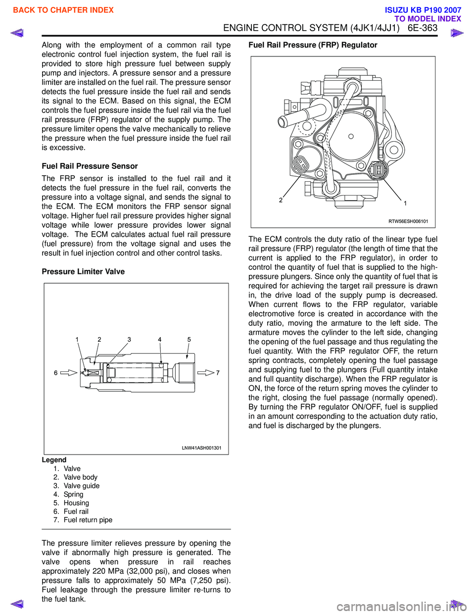
Pressure Limiter Valve
Legend 1. Valve
2. Valve body
3. Valve guide
4. Spring
5. Housing
6. Fuel rail
7. Fuel return pipe
The pressure limiter relieves pressure by opening the
valve if abnormally high pressure is generated. The
valve opens when pressure in rail reaches
approximately 220 MPa (32,000 psi), and closes when
pressure falls to approximately 50 MPa (7,250 psi).
Fuel leakage through the pressure limiter re-turns to
the fuel tank. Fuel Rail Pressure (FRP) Regulator
The ECM controls the duty ratio of the linear type fuel
rail pressure (FRP) regulator (the length of time that the
current is applied to the FRP regulator), in order to
control the quantity of fuel that is supplied to the high-
pressure plungers. Since only the quantity of fuel that is
required for achieving the target rail pressure is drawn
in, the drive load of the supply pump is decreased.
When current flows to the FRP regulator, variable
electromotive force is created in accordance with the
duty ratio, moving the armature to the left side. The
armature moves the cylinder to the left side, changing
the opening of the fuel passage and thus regulating the
fuel quantity. With the FRP regulator OFF, the return
spring contracts, completely opening the fuel passage
and supplying fuel to the plungers (Full quantity intake
and full quantity discharge). When the FRP regulator is
ON, the force of the return spring moves the cylinder to
the right, closing the fuel passage (normally opened).
By turning the FRP regulator ON/OFF, fuel is supplied
in an amount corresponding to the actuation duty ratio,
and fuel is discharged by the plungers.
LNW41ASH001301
12 3 4 5
7
6
RTW56ESH006101
12
BACK TO CHAPTER INDEX
TO MODEL INDEX
ISUZU KB P190 2007
Page 2013 of 6020
ENGINE DIAGNOSIS (C24SE) 6-13
Fuel Consumption Excessive
Condition Possible cause Correction
Trouble in fuel system Mixture too rich or too lean due to
trouble in fuel injection system Refer to "Abnormal Combustion"
Fuel cut function does not act Refer to "Abnormal Combustion"
Trouble in ignition system Misfiring or abnormal combustion
due to trouble in ignition system Refer to Hard Start or Abnormal
Combustion Troubleshooting
Guide
Others Engine idle speed too high Reset Idle Air Control Valve
Returning of accelerator control
sluggish Correct
Fuel system leakage Correct or replace
Clutch slipping Correct
Brake drag Correct
Selection of transmission gear
incorrect Caution operator of incorrect gear
selection
Oil Problems
Condition Possible cause Correction
Oil pressure too low Wrong oil in use Replace with correct engine oil
Relief valve sticking Replace
Oil pump not operating properly Correct or replace
Oil pump strainer clogged Clean or replace strainer
Oil pump worn Replace
Oil pressure gauge defective Correct or replace
Crankshaft bearing or connecting
rod bearing worn Replace
Oil contamination
Wrong oil in use Replace with new engine oil
Oil filter clogged Replace oil filter
Cylinder head gasket damage Replace gasket
Burned gases leaking Replace piston and piston rings or
rebore cylinders
Oil not reaching valve system Oil passage in cylinder head or cylinder body clogged Clean or correct
Engine Oil Pressure Check
1. Check for dirt, gasoline or water in the engine
oil.
a. Check the viscosity of the oil.
b. Change the oil if the viscosity is outside the specified standard.
c. Refer to the "Maintenance and Lubrication" section of this manual.
2. Check the engine oil level. The level should fall somewhere between the
"ADD" and the "FULL" marks on the oil level
dipstick.
If the oil level does not reach the "ADD" mark on
the oil level dipstick, engine oil must be added.
3. Remove the oil pressure unit.
4. Install an oil pressure gauge.
5. Start the engine and allow the engine to reach normal operating temperature (About 80 °C).
6. Measure the oil pressure.
Oil pressure should be:
150 kPa(21.8 psi) at idle speed.
7. Stop the engine.
8. Remove the oil pressure gauge
9. Install the oil pressure unit.
10. Start the engine and check for leaks.
BACK TO CHAPTER INDEX
TO MODEL INDEX
ISUZU KB P190 2007
Page 2087 of 6020
ENGINE MECHANICAL (C24SE) 6A-73
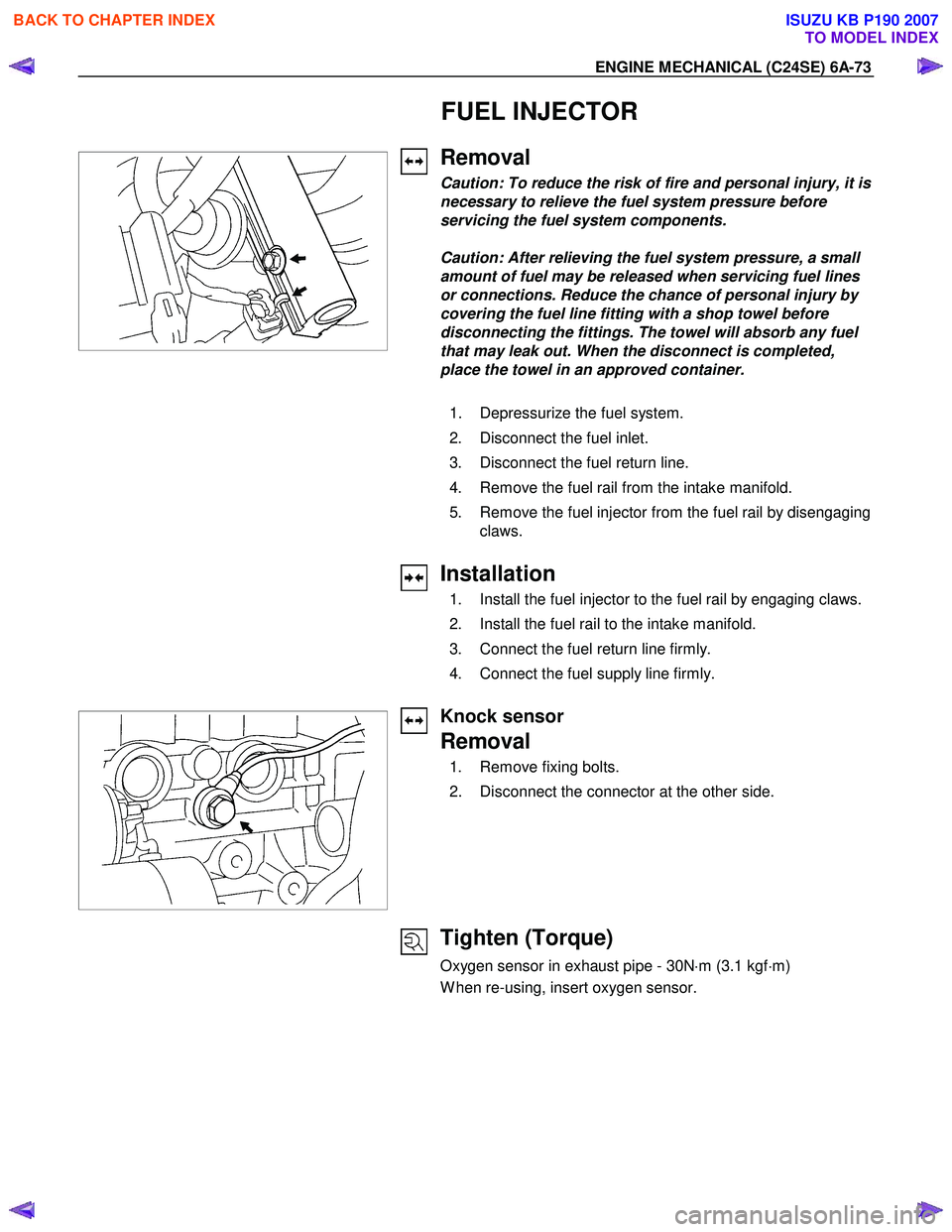
FUEL INJECTOR
Removal
Caution: To reduce the risk of fire and personal injury, it is
necessary to relieve the fuel system pressure before
servicing the fuel system components.
Caution: After relieving the fuel system pressure, a small
amount of fuel may be released when servicing fuel lines
or connections. Reduce the chance of personal injury by
covering the fuel line fitting with a shop towel before
disconnecting the fittings. The towel will absorb any fuel
that may leak out. When the disconnect is completed,
place the towel in an approved container.
1. Depressurize the fuel system.
2. Disconnect the fuel inlet.
3. Disconnect the fuel return line.
4. Remove the fuel rail from the intake manifold.
5. Remove the fuel injector from the fuel rail by disengaging claws.
Installation
1. Install the fuel injector to the fuel rail by engaging claws.
2. Install the fuel rail to the intake manifold.
3. Connect the fuel return line firmly.
4. Connect the fuel supply line firmly.
Knock sensor
Removal
1. Remove fixing bolts.
2. Disconnect the connector at the other side.
Tighten (Torque)
Oxygen sensor in exhaust pipe - 30N ⋅m (3.1 kgf ⋅m)
W hen re-using, insert oxygen sensor.
BACK TO CHAPTER INDEX
TO MODEL INDEX
ISUZU KB P190 2007
Page 2121 of 6020
ENGINE FUEL (C24SE) 6C-3
W hen working on the fuel system, there are several things to
keep in mind:
•
Any time the fuel system is being worked on, disconnect the
negative battery cable except for those tests where batter
y
voltage is required.
•
Always keep a dry chemical (Class B) fire extinguisher near
the work area.
• Replace all pipes with the same pipe and fittings that were
removed.
• Clean and inspect "O" rings. Replace if required.
•
Always relieve the line pressure before servicing any fuel
system components.
• Do not attempt repairs on the fuel system until you have
read the instructions and checked the pictures relating to
that repair.
• Adhere to all Notices and Cautions.
All gasoline engines are designed to use only unleaded
gasoline. Unleaded gasoline must be used for proper emission
control system operation.
Its use will also minimize spark plug fouling and extend engine
oil life. Using leaded gasoline can damage the emission control
system and could result in loss of emission warranty coverage.
All cars are equipped with an Evaporative Emission Control
System. The purpose of the system is to minimize the escape
of fuel vapors to the atmosphere.
Service Precaution
CAUTION:
Always use the correct fastener in the proper location.
When you replace a fastener, use ONLY the exact part
number for that application. ISUZU will call out those
fasteners that require a replacement after removal. ISUZU
will also call out the fasteners that require thread lockers
or thread sealant. UNLESS OTHERWISE SPECIFIED, do
not use supplemental coatings (Paints, greases, or othe
r
corrosion inhibitors) on threaded fasteners or fastene
r
joint interfaces. Generally, such coatings adversely affect
the fastener torque and the joint clamping force, and may
damage the fastener. When you install fasteners, use the
correct tightening sequence and specifications. Following
these instructions can help you avoid damage to parts
and systems.
BACK TO CHAPTER INDEX
TO MODEL INDEX
ISUZU KB P190 2007
Page 2132 of 6020
6C-14 ENGINE FUEL (C24SE)
Removal
CAUTION: When repair to the fuel system has been
completed, start engine and check the fuel system
for loose connection or leakage. For the fuel system
diagnosis, see Section “Driveability and Emission".
1. Disconnect battery ground cable.
2. Loosen slowly the fuel filler cap.
NOTE: To prevent spouting out fuel to change the
pressure in the fuel tank.
NOTE: Cover opening of the filler neck to prevent an
y
dust entering.
3. Jack up the vehicle.
4. Support underneath of the fuel tank with a lifter.
5. Remove the inner liner of the wheel house on rea
r
left side.
6. Remove fasten bolt to the filler neck from the body.
7. Disconnect the quick connector (8) into the fuel
tube from the fuel pipe and the evapo tube from
evapo joint connector.
NOTE: Cover the quick connector to prevent any dust
entering and fuel leaking.
NOTE: Refer to “Fuel Tube/Quick Connector Fittings” in
this section when performing any repairs.
8. Remove fasten bolt (1) to the tank band and the tank band (2).
9. Disconnect the pump and sender connector on the
fuel pump and remove the harness from weld clip
on the fuel tank.
10. Lower the fuel tank (6).
NOTE: W hen the fuel tank is lowered from the vehicle,
don’t scratch each hose and tube by around other pars.
Installation
1. Rise the fuel tank into position.
NOTE: Ensure hoses and tubes do not foul on othe
r
component. 2. Connect the pump and sender connector to the
fuel pump and install harness to into the plastic clip
welded to the top of the fuel tank..
NOTE: The connector must be certainly connected
against stopper.
Ensure tank band anchor mates with guide hole on
frame.
3. Install the tank band to fasten bolt.
Torque: 68 N ⋅
⋅⋅
⋅
m (6.9kg ⋅
⋅⋅
⋅
m/50 lb ft)
NOTE: The anchor of the tank band must be certainl
y
installed to guide hole on frame. 4. Connect the quick connector from the fuel tube to
the fuel pipe and the evapo tube from evapo joint
connector.
NOTE: Pull off the left checker into the fuel pipe.
NOTE: Refer to “Fuel Tube/Quick Connector Fittings” in
this section when performing any repairs.
5. Install the filler neck to the body by bolt.
6. Install the inner liner of the wheel house on rea
r
side.
7. Remove lifter to support underneath of the fuel tank.
8. Put back the vehicle.
9. Tigten the filler cap until at least three clicks are
heard.
10. Connect the battery ground cable.
BACK TO CHAPTER INDEX
TO MODEL INDEX
ISUZU KB P190 2007