2007 ISUZU KB P190 Fuel line
[x] Cancel search: Fuel linePage 2288 of 6020
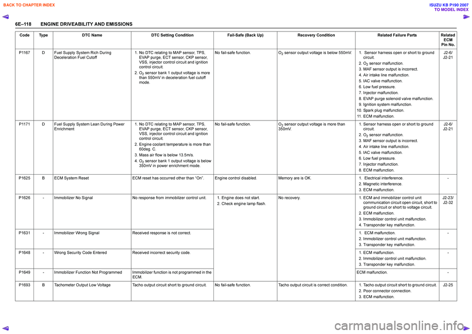
6E–118 ENGINE DRIVEABILITY AND EMISSIONSP1167 D Fuel Supply System Rich During
Deceleration Fuel Cutoff 1. No DTC relating to MAP sensor, TPS,
EVAP purge, ECT sensor, CKP sensor,
VSS, injector control circuit and ignition
control circuit.
2. O
2 sensor bank 1 output voltage is more
than 550mV in deceleration fuel cutoff
mode. No fail-safe function.
O
2 sensor output voltage is below 550mV. 1. Sensor harness open or short to ground
circuit.
2. O
2 sensor malfunction.
3. MAF sensor output is incorrect.
4. Air intake line malfunction.
5. IAC valve malfunction.
6. Low fuel pressure.
7. Injector malfunction.
8. EVAP purge solenoid valve malfunction.
9. Ignition system malfunction.
10. Spark plug malfunction. 11. ECM malfunction. J2-6/
J2-21
P1171 D Fuel Supply System Lean During Power Enrichment 1. No DTC relating to MAP sensor, TPS,
EVAP purge, ECT sensor, CKP sensor,
VSS, injector control circuit and ignition
control circuit.
2. Engine coolant temperature is more than 60deg. C.
3. Mass air flow is below 13.5m/s.
4. O
2 sensor bank 1 output voltage is below
350mV in power enrichment mode. No fail-safe function.
O
2 sensor output voltage is more than
350mV. 1. Sensor harness open or short to ground
circuit.
2. O
2 sensor malfunction.
3. MAF sensor output is incorrect.
4. Air intake line malfunction.
5. IAC valve malfunction.
6. Low fuel pressure.
7. Injector malfunction.
8. ECM malfunction. J2-6/
J2-21
P1625 B ECM System Reset ECM reset has occurred other than “On ”. Engine control disabled. Memory are is OK. 1. Electrical interference.
2. Magnetic interference.
3. ECM malfunction. -
P1626 - Immobilizer No Signal No response from immobilizer control unit. 1. Engine does not start.
2. Check engine lamp flash.No recovery.
1. ECM and immobilizer control unit
communication circuit open circuit, short to
ground circuit or short to voltage circuit.
2. ECM malfunction.
3. Immobilizer control unit malfunction.
4. Transponder key malfunction. J2-23/
J2-32
P1631 - Immobilizer Wrong Signal Received response is not correct. 1. ECM malfunction.
2. Immobilizer control unit malfunction.
3. Transponder key malfunction. -
P1648 - Wrong Security Code Entered Received incorrect security code. 1. ECM malfunction.
2. Immobilizer control unit malfunction.
3. Transponder key malfunction. -
P1649 - Immobilizer Function Not Programmed Immobilizer function is not programmed in the ECM. ECM malfunction.
-
P1693 B Tachometer Output Low Voltage Tacho output circuit short to ground circuit. No fail-safe function. Tacho output circuit is correct condition. 1. Tacho output circuit short to ground circuit.
2. Poor connector connection.
3. ECM malfunction. J2-25
Code Type
DTC Name DTC Setting Condition Fail-Safe (Back Up)Recovery Condition Related Failure PartsRelated
ECM
Pin No.
BACK TO CHAPTER INDEX
TO MODEL INDEX
ISUZU KB P190 2007
Page 2326 of 6020
6E–156 ENGINE DRIVEABILITY AND EMISSIONS
Fuel System Diagnosis.
• Perform “Injector Balance Test” - Refer to Fuel System Diagnosis.
• Check the EVAP canister for fuel saturation - If full of fuel, check canister control and hoses. Refer to
Evaporative (EVAP) Emission Control System.
• Check for a leak in the fuel pressure regulator diaphragm by checking the vacuum line to the
regulator for the presence of fuel. • An intermittent TPS output will cause the system to
go rich due to a false indication of the engine
accelerating.
• Silicon contamination of the HO2S can also cause a high HO2S voltage to be indicated. This condition is
indicated by a powdery white deposit on the portion
of the HO2S exposed to the exhaust stream. If
contamination is noticed, replace the affected HO2S.
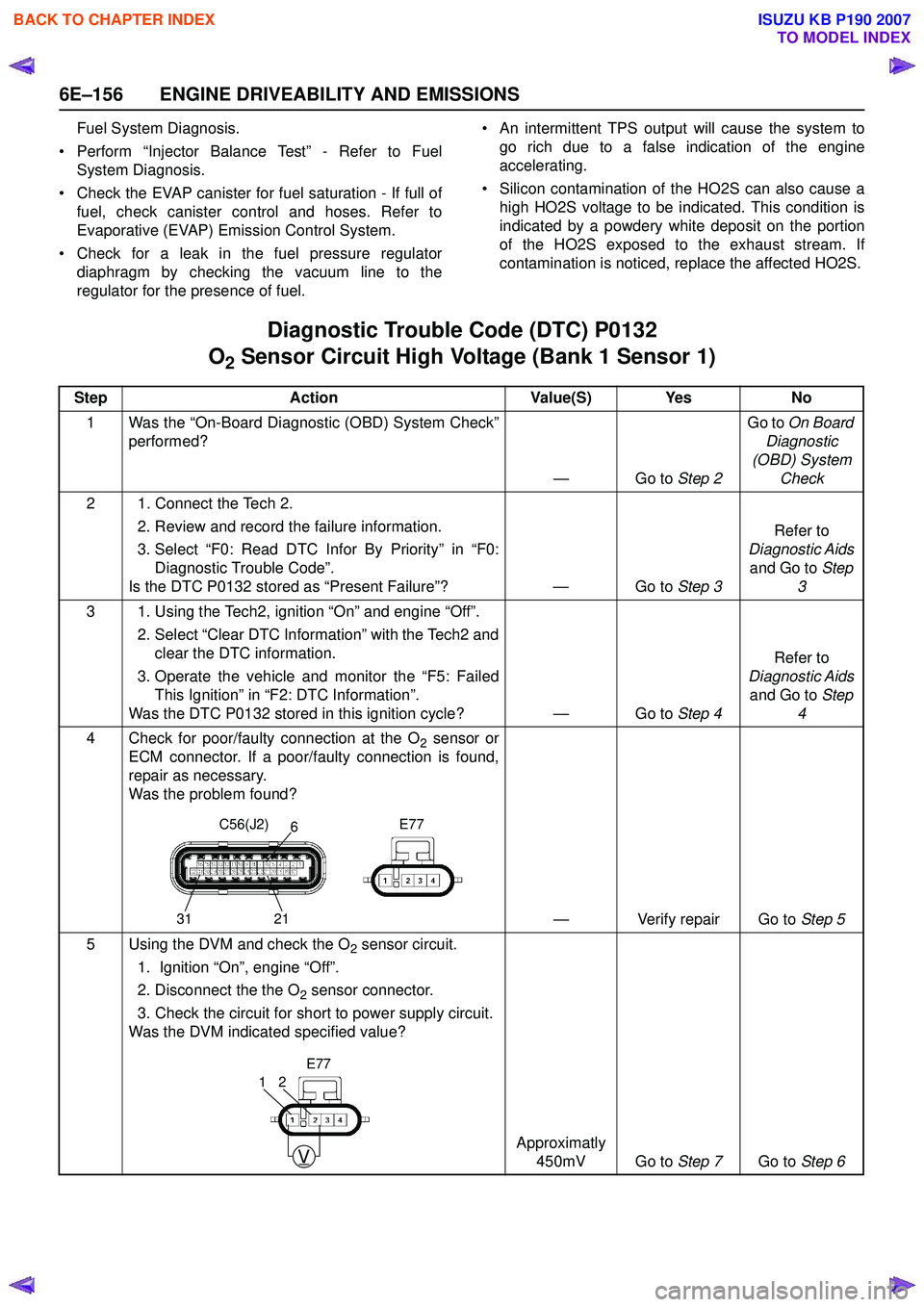
Diagnostic Trouble Code (DTC) P0132
O
2 Sensor Circuit High Voltage (Bank 1 Sensor 1)
Step Action Value(S) Yes No
1 Was the “On-Board Diagnostic (OBD) System Check” performed?
—Go to Step 2Go to
On Board
Diagnostic
(OBD) System Check
2 1. Connect the Tech 2. 2. Review and record the failure information.
3. Select “F0: Read DTC Infor By Priority” in “F0: Diagnostic Trouble Code”.
Is the DTC P0132 stored as “Present Failure”? — Go to Step 3Refer to
Diagnostic Aids and Go to Step
3
3 1. Using the Tech2, ignition “On” and engine “Off”. 2. Select “Clear DTC Information” with the Tech2 andclear the DTC information.
3. Operate the vehicle and monitor the “F5: Failed This Ignition” in “F2: DTC Information”.
Was the DTC P0132 stored in this ignition cycle? — Go to Step 4Refer to
Diagnostic Aids and Go to Step
4
4 Check for poor/faulty connection at the O
2 sensor or
ECM connector. If a poor/faulty connection is found,
repair as necessary.
Was the problem found?
— Verify repair Go to Step 5
5 Using the DVM and check the O
2 sensor circuit.
1. Ignition “On”, engine “Off”.
2. Disconnect the the O
2 sensor connector.
3. Check the circuit for short to power supply circuit.
Was the DVM indicated specified value?
Approximatly 450mV Go to Step 7Go to Step 6
C56(J2) E77
31 216
V
21
E77
BACK TO CHAPTER INDEX
TO MODEL INDEX
ISUZU KB P190 2007
Page 2382 of 6020
6E–212 ENGINE DRIVEABILITY AND EMISSIONS
• Perform “Injector Balance Test” - Refer to Fuel
System Diagnosis .
• Check the EVAP canister for fuel saturation - If full of fuel, check canister control and hoses. Refer to
Evaporative (EVAP) Emission Control System .
• Check for a leak in the fuel pressure regulator diaphragm by checking the vacuum line to toe
regulator for the presence of fuel. • An intermittent TP sensor output will cause the
system to go rich due to a false indication of the
engine accelerating.
• Silicon contamination of the HO2S can also cause a high HO2S voltage to be indicated. This condition is
indicated by a powdery white deposit on the portion
of the HO2S exposed to the exhaust stream. If
contamination is noticed, replace the affected HO2S.
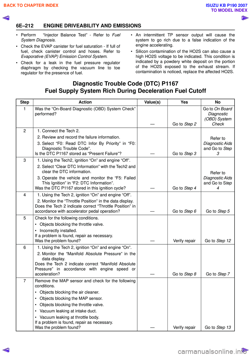
Diagnostic Trouble Code (DTC) P1167
Fuel Supply System Rich During Deceleration Fuel Cutoff
Step Action Value(s) Yes No
1 Was the “On-Board Diagnostic (OBD) System Check” performed?
—Go to Step 2Go to
On Board
Diagnostic
(OBD) System Check
2 1. Connect the Tech 2. 2. Review and record the failure information.
3. Select “F0: Read DTC Infor By Priority” in “F0: Diagnostic Trouble Code”.
Is the DTC P1167 stored as “Present Failure”? — Go to Step 3Refer to
Diagnostic Aids and Go to Step
3
3 1. Using the Tech2, ignition “On” and engine “Off”. 2. Select “Clear DTC Information” with the Tech2 andclear the DTC information.
3. Operate the vehicle and monitor the “F5: Failed This Ignition” in “F2: DTC Information”.
Was the DTC P1167 stored in this ignition cycle? — Go to Step 4Refer to
Diagnostic Aids and Go to S tep
4
4 1. Using the Tech 2, ignition “On” and engine “Off”. 2. Monitor the “Throttle Position” in the data display.
Does the Tech 2 indicate correct “Throttle Position” in
accordance with accelerator pedal operation? — Go to Step 6Go to Step 5
5 Check for the following conditions. • Objects blocking the throttle valve.
• Incorrectly installed.
If a problem is found, repair as necessary.
Was the problem found? — Verify repair Go to Step 12
6 1. Using the Tech 2, ignition “On” and engine “On”. 2. Monitor the “Manifold Absolute Pressure” in thedata display.
Does the Tech 2 indicate correct “Manifold Absolute
Pressure” in accordance with engine speed or
acceleration? — Go to Step 8Go to Step 7
7 Remove the MAP sensor and check for the following conditions.
• Objects blocking the air cleaner.
• Objects blocking the MAP sensor.
• Objects blocking the throttle valve.
• Vacuum leaking at intake duct.
• Vacuum leaking at throttle body.
If a problem is found, repair as necessary.
Was the problem found? — Verify repair Go to Step 13
BACK TO CHAPTER INDEX
TO MODEL INDEX
ISUZU KB P190 2007
Page 2384 of 6020
6E–214 ENGINE DRIVEABILITY AND EMISSIONS
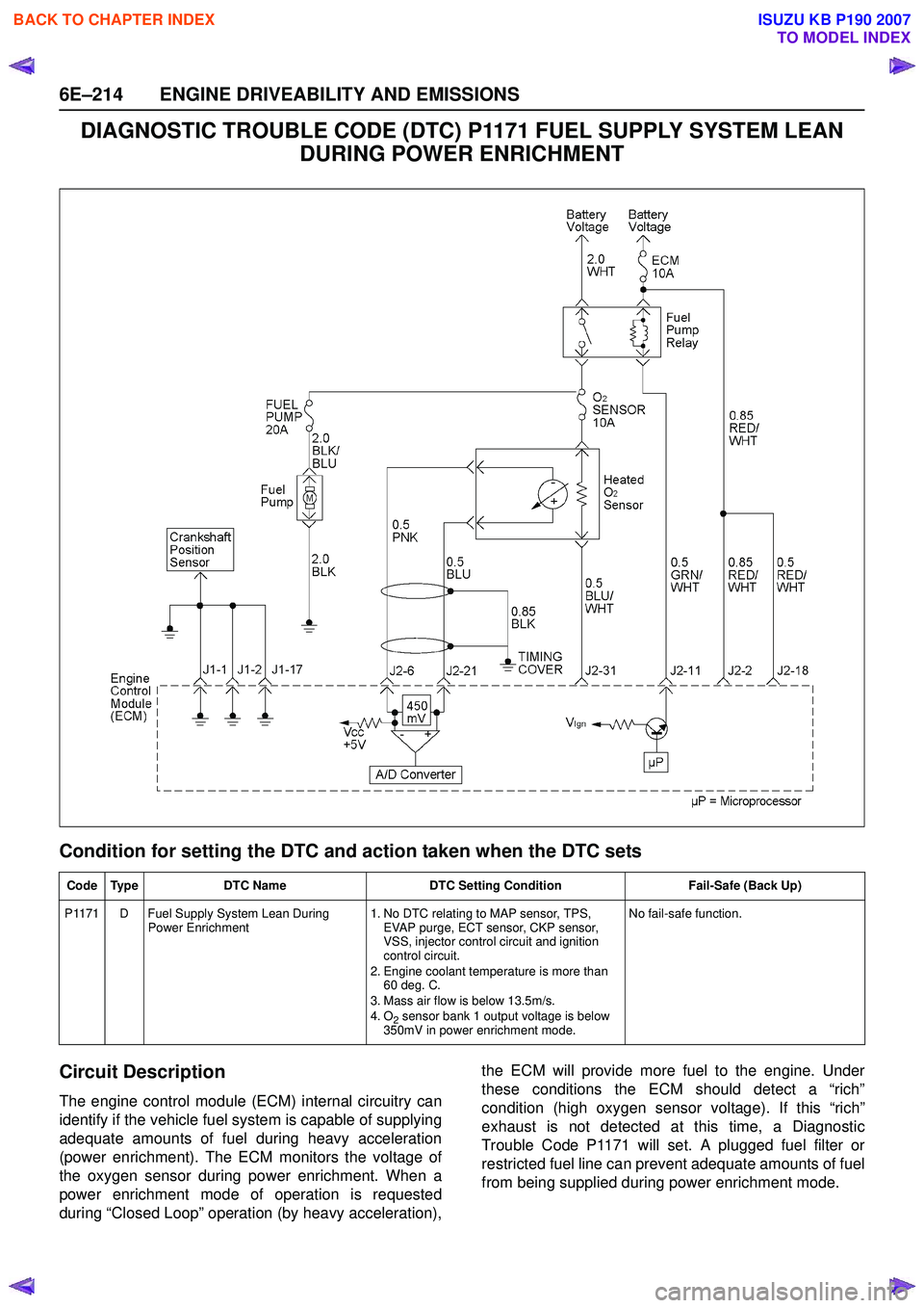
DIAGNOSTIC TROUBLE CODE (DTC) P1171 FUEL SUPPLY SYSTEM LEAN DURING POWER ENRICHMENT
Condition for setting the DTC and action taken when the DTC sets
Circuit Description
The engine control module (ECM) internal circuitry can
identify if the vehicle fuel system is capable of supplying
adequate amounts of fuel during heavy acceleration
(power enrichment). The ECM monitors the voltage of
the oxygen sensor during power enrichment. When a
power enrichment mode of operation is requested
during “Closed Loop” operation (by heavy acceleration), the ECM will provide more fuel to the engine. Under
these conditions the ECM should detect a “rich”
condition (high oxygen sensor voltage). If this “rich”
exhaust is not detected at this time, a Diagnostic
Trouble Code P1171 will set. A plugged fuel filter or
restricted fuel line can prevent adequate amounts of fuel
from being supplied during power enrichment mode.
Code Type DTC Name DTC Setting Condition Fail-Safe (Back Up)
P1171 D Fuel Supply System Lean During Power Enrichment 1. No DTC relating to MAP sensor, TPS,
EVAP purge, ECT sensor, CKP sensor,
VSS, injector control circuit and ignition
control circuit.
2. Engine coolant temperature is more than 60 deg. C.
3. Mass air flow is below 13.5m/s.
4. O
2 sensor bank 1 output voltage is below
350mV in power enrichment mode. No fail-safe function.
BACK TO CHAPTER INDEX
TO MODEL INDEX
ISUZU KB P190 2007
Page 2424 of 6020
6E–254 ENGINE DRIVEABILITY AND EMISSIONS
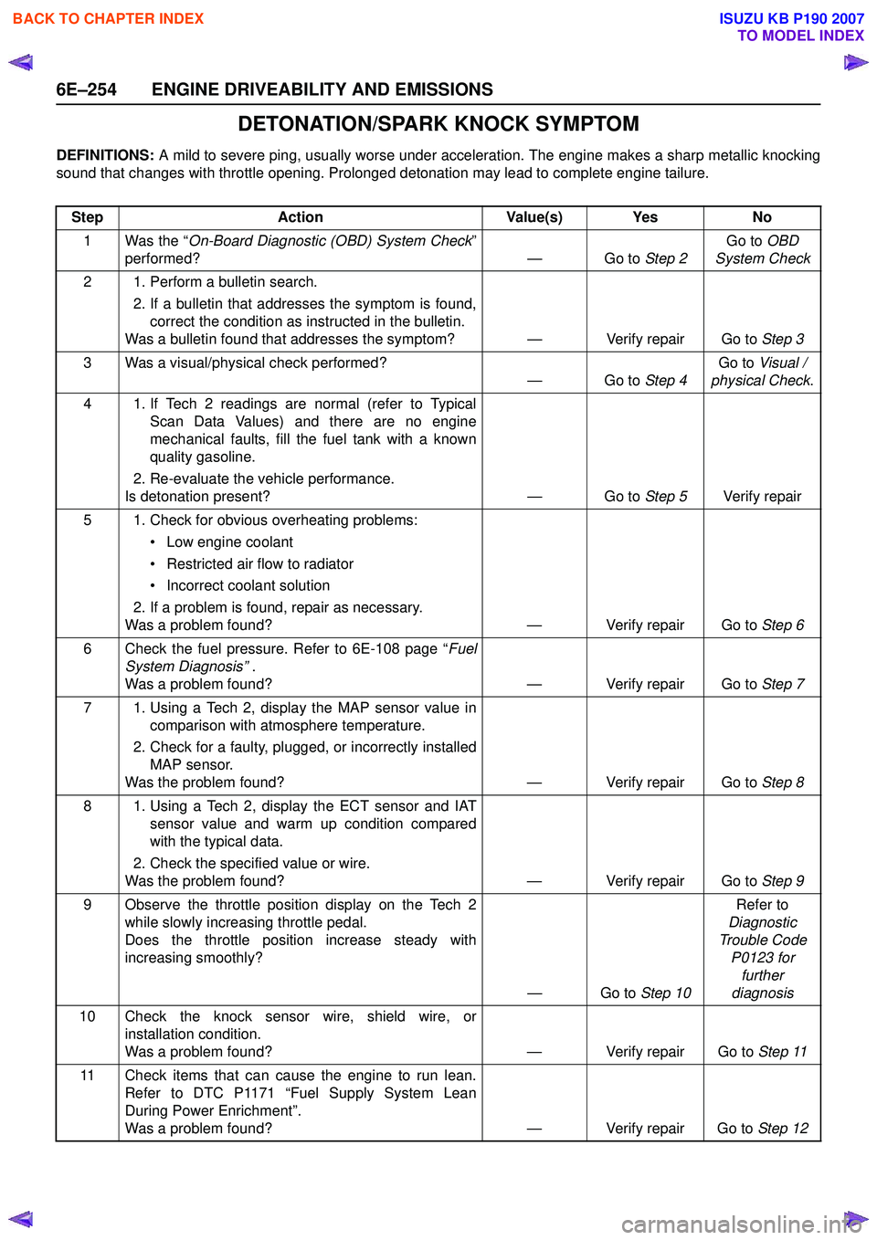
DETONATION/SPARK KNOCK SYMPTOM
DEFINITIONS: A mild to severe ping, usually worse under acceleration. The engine makes a sharp metallic knocking
sound that changes with throttle opening. Prolonged detonation may lead to complete engine tailure.
Step Action Value(s) Yes No
1 Was the “ On-Board Diagnostic (OBD) System Check ”
performed? — Go to Step 2Go to
OBD
System Check
2 1. Perform a bulletin search. 2. If a bulletin that addresses the symptom is found,correct the condition as instructed in the bulletin.
Was a bulletin found that addresses the symptom? — Verify repair Go to Step 3
3 Was a visual/physical check performed? —Go to Step 4Go to
Visual /
physical Check .
4 1. If Tech 2 readings are normal (refer to Typical Scan Data Values) and there are no engine
mechanical faults, fill the fuel tank with a known
quality gasoline.
2. Re-evaluate the vehicle performance.
Is detonation present? — Go to Step 5Verify repair
5 1. Check for obvious overheating problems: • Low engine coolant
• Restricted air flow to radiator
• Incorrect coolant solution
2. If a problem is found, repair as necessary.
Was a problem found? — Verify repair Go to Step 6
6 Check the fuel pressure. Refer to 6E-108 page “ Fuel
System Diagnosis” .
Was a problem found? — Verify repair Go to Step 7
7 1. Using a Tech 2, display the MAP sensor value in comparison with atmosphere temperature.
2. Check for a faulty, plugged, or incorrectly installed MAP sensor.
Was the problem found? — Verify repair Go to Step 8
8 1. Using a Tech 2, display the ECT sensor and IAT sensor value and warm up condition compared
with the typical data.
2. Check the specified value or wire.
Was the problem found? — Verify repair Go to Step 9
9 Observe the throttle position display on the Tech 2 while slowly increasing throttle pedal.
Does the throttle position increase steady with
increasing smoothly?
—Go to Step 10Refer to
Diagnostic
Trouble Code P0123 for further
diagnosis
10 Check the knock sensor wire, shield wire, or installation condition.
Was a problem found? — Verify repair Go to Step 11
11 Check items that can cause the engine to run lean. Refer to DTC P1171 “Fuel Supply System Lean
During Power Enrichment”.
Was a problem found? — Verify repair Go to Step 12
BACK TO CHAPTER INDEX
TO MODEL INDEX
ISUZU KB P190 2007
Page 2428 of 6020
6E–258 ENGINE DRIVEABILITY AND EMISSIONS
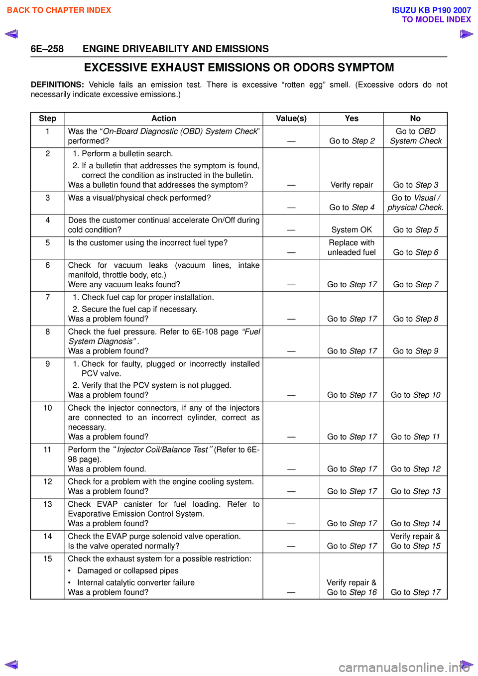
EXCESSIVE EXHAUST EMISSIONS OR ODORS SYMPTOM
DEFINITIONS: Vehicle fails an emission test. There is excessive “rotten egg” smell. (Excessive odors do not
necessarily indicate excessive emissions.)
Step Action Value(s) Yes No
1 Was the “ On-Board Diagnostic (OBD) System Check ”
performed? — Go to Step 2Go to
OBD
System Check
2 1. Perform a bulletin search. 2. If a bulletin that addresses the symptom is found,correct the condition as instructed in the bulletin.
Was a bulletin found that addresses the symptom? — Verify repair Go to Step 3
3 Was a visual/physical check performed? —Go to Step 4Go to
Visual /
physical Check .
4 Does the customer continual accelerate On/Off during cold condition? — System OK Go to Step 5
5 Is the customer using the incorrect fuel type? —Replace with
unleaded fuel Go to Step 6
6 Check for vacuum leaks (vacuum lines, intake manifold, throttle body, etc.)
Were any vacuum leaks found? — Go to Step 17Go to Step 7
7 1. Check fuel cap for proper installation. 2. Secure the fuel cap if necessary.
Was a problem found? — Go to Step 17Go to Step 8
8 Check the fuel pressure. Refer to 6E-108 page “Fuel
System Diagnosis” .
Was a problem found? — Go to Step 17Go to Step 9
9 1. Check for faulty, plugged or incorrectly installed PCV valve.
2. Verify that the PCV system is not plugged.
Was a problem found? — Go to Step 17Go to Step 10
10 Check the injector connectors, if any of the injectors are connected to an incorrect cylinder, correct as
necessary.
Was a problem found? — Go to Step 17Go to Step 11
11 Perform the “Injector Coil/Balance Test
” (Refer to 6E-
98 page).
Was a problem found. — Go to Step 17Go to Step 12
12 Check for a problem with the engine cooling system. Was a problem found? — Go to Step 17Go to Step 13
13 Check EVAP canister for fuel loading. Refer to Evaporative Emission Control System.
Was a problem found? — Go to Step 17Go to Step 14
14 Check the EVAP purge solenoid valve operation. Is the valve operated normally? — Go to Step 17Verify repair &
Go to Step 15
15 Check the exhaust system for a possible restriction: • Damaged or collapsed pipes
• Internal catalytic converter failure
Was a problem found? —Verify repair &
Go to Step 16 Go to Step 17
BACK TO CHAPTER INDEX
TO MODEL INDEX
ISUZU KB P190 2007
Page 2440 of 6020
6E–270 ENGINE DRIVEABILITY AND EMISSIONS
FUEL PRESSURE RELIEF
Caution: To reduce the risk of fire and personal
injury, it is necessary to relieve the fuel system
pressure before servicing the fuel system
components.
Caution: After relieving the fuel system pressure, a
small amount of fuel may be released when
servicing fuel lines or connections. Reduce the
chance of personal injury by covering the fuel line
fitting with a short towel before disconnecting the
fittings. The towel will absorb any fuel that may leak
out. When the disconnect is completed, place the
towel in an approved container.
1. Remove the fuel filler cap.
2. Remove the fuel pump relay from the underhood relay box.
3. Start the engine and allow it to stall.
4. Crank the engine for about 30 seconds.
5. Disconnect the negative battery cable.
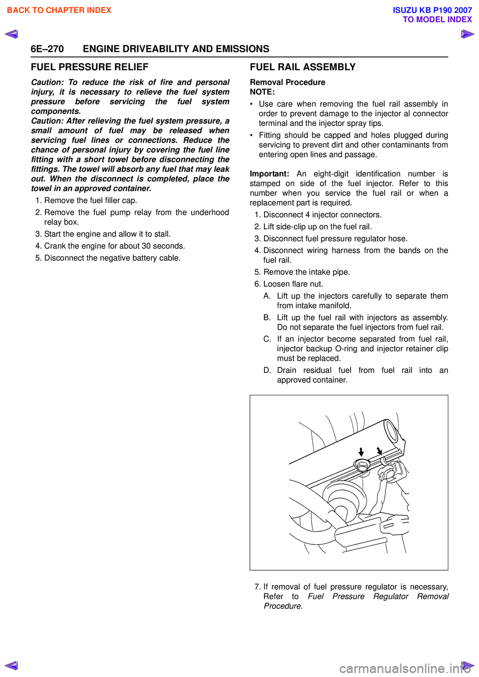
FUEL RAIL ASSEMBLY
Removal Procedure
NOTE:
• Use care when removing the fuel rail assembly in order to prevent damage to the injector al connector
terminal and the injector spray tips.
• Fitting should be capped and holes plugged during servicing to prevent dirt and other contaminants from
entering open lines and passage.
Important: An eight-digit identification number is
stamped on side of the fuel injector. Refer to this
number when you service the fuel rail or when a
replacement part is required.
1. Disconnect 4 injector connectors.
2. Lift side-clip up on the fuel rail.
3. Disconnect fuel pressure regulator hose.
4. Disconnect wiring harness from the bands on the fuel rail.
5. Remove the intake pipe.
6. Loosen flare nut.
A. Lift up the injectors carefully to separate them from intake manifold.
B. Lift up the fuel rail with injectors as assembly. Do not separate the fuel injectors from fuel rail.
C. If an injector become separated from fuel rail, injector backup O-ring and injector retainer clip
must be replaced.
D. Drain residual fuel from fuel rail into an approved container.
7. If removal of fuel pressure regulator is necessary, Refer to Fuel Pressure Regulator Removal
Procedure .
BACK TO CHAPTER INDEX
TO MODEL INDEX
ISUZU KB P190 2007
Page 2441 of 6020
ENGINE DRIVEABILITY AND EMISSIONS 6E–271
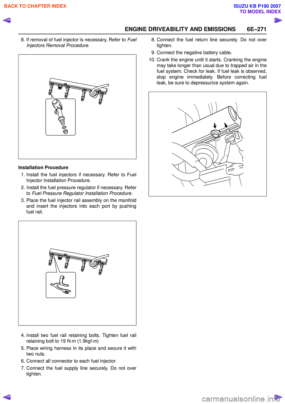
8. If removal of fuel injector is necessary, Refer to Fuel
Injectors Removal Procedure .
Installation Procedure 1. Install the fuel injectors if necessary. Refer to Fuel Injector Installation Procedure.
2. Install the fuel pressure regulator if necessary. Refer to Fuel Pressure Regulator Installation Procedure .
3. Place the fuel injector rail assembly on the manifold and insert the injectors into each port by pushing
fuel rail.
4. Install two fuel rail retaining bolts. Tighten fuel rail retaining bolt to 19 N·m (1.9kgf·m)
5. Place wiring harness in its place and secure it with two nuts.
6. Connect all connector to each fuel injector.
7. Connect the fuel supply line securely. Do not over tighten. 8. Connect the fuel return line securely. Do not over
tighten.
9. Connect the negative battery cable.
10. Crank the engine until it starts. Cranking the engine may take longer than usual due to trapped air in the
fuel system. Check for leak. If fuel leak is observed,
stop engine immediately. Before correcting fuel
leak, be sure to depressurize system again.
BACK TO CHAPTER INDEX
TO MODEL INDEX
ISUZU KB P190 2007