Page 3234 of 6020

Fuel System – V6 Page 6C – 32
4.8 Fuel Filler Cap
The fuel filler cap is a 'screw on' type, with an integrated tightening torque limiting mechanism. W hen installing the fuel
filler cap, tighten it until a ratcheting (clicking) sound is audible, indicating the fuel filler cap is properly tightened. Th e fuel
filler cap is tethered to the fuel filler pocket.
Remove
The fuel filler cap requires a quarter of a turn anticlockwise to be removed.
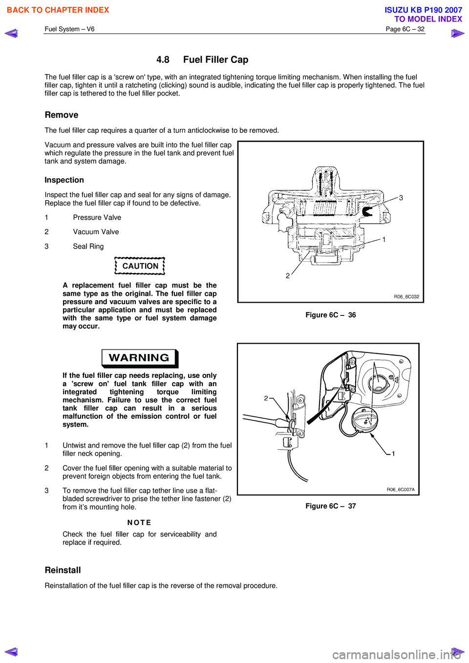
Vacuum and pressure valves are built into the fuel filler cap
which regulate the pressure in the fuel tank and prevent fuel
tank and system damage.
Inspection
Inspect the fuel filler cap and seal for any signs of damage.
Replace the fuel filler cap if found to be defective.
1 Pressure Valve
2 Vacuum Valve
3 Seal Ring
A replacement fuel filler cap must be the
same type as the original. The fuel filler cap
pressure and vacuum valves are specific to a
particular application and must be replaced
with the same type or fuel system damage
may occur.
Figure 6C – 36
If the fuel filler cap needs replacing, use only
a 'screw on' fuel tank filler cap with an
integrated tightening torque limiting
mechanism. Failure to use the correct fuel
tank filler cap can result in a serious
malfunction of the emission control or fuel
system.
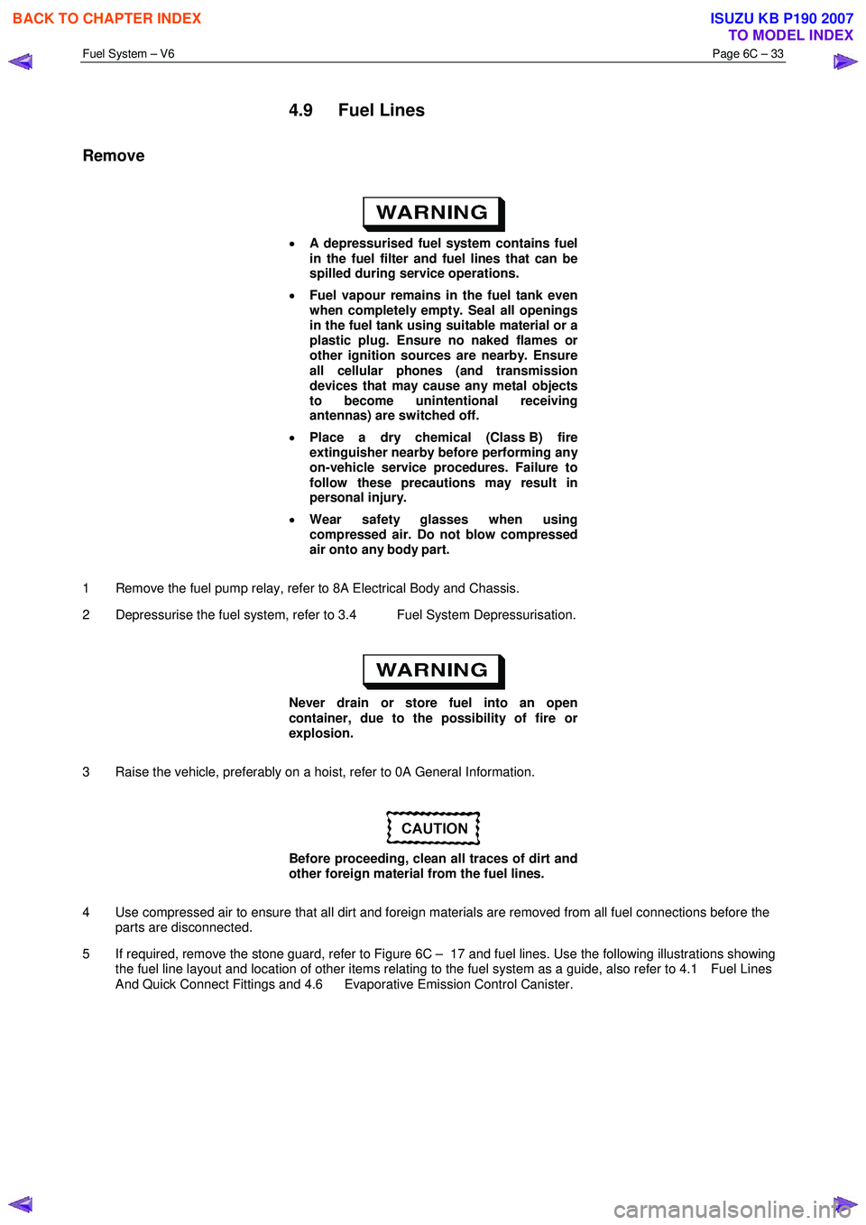
1 Untwist and remove the fuel filler cap (2) from the fuel filler neck opening.
2 Cover the fuel filler opening with a suitable material to prevent foreign objects from entering the fuel tank.
3 To remove the fuel filler cap tether line use a flat- bladed screwdriver to prise the tether line fastener (2)
from it’s mounting hole.
NOTE
Check the fuel filler cap for serviceability and
replace if required.
Figure 6C – 37
Reinstall
Reinstallation of the fuel filler cap is the reverse of the removal procedure.
BACK TO CHAPTER INDEX
TO MODEL INDEX
ISUZU KB P190 2007
Page 3235 of 6020

Fuel System – V6 Page 6C – 33
4.9 Fuel Lines
Remove
• A depressurised fuel system contains fuel
in the fuel filter and fuel lines that can be
spilled during service operations.
• Fuel vapour remains in the fuel tank even
when completely empty. Seal all openings
in the fuel tank using suitable material or a
plastic plug. Ensure no naked flames or
other ignition sources are nearby. Ensure
all cellular phones (and transmission
devices that may cause any metal objects
to become unintentional receiving
antennas) are switched off.
• Place a dry chemical (Class B) fire
extinguisher nearby before performing any
on-vehicle service procedures. Failure to
follow these precautions may result in
personal injury.
• Wear safety glasses when using
compressed air. Do not blow compressed
air onto any body part.
1 Remove the fuel pump relay, refer to 8A Electrical Body and Chassis.
2 Depressurise the fuel system, refer to 3.4 Fuel System Depressurisation.
Never drain or store fuel into an open
container, due to the possibility of fire or
explosion.
3 Raise the vehicle, preferably on a hoist, refer to 0A General Information.
Before proceeding, clean all traces of dirt and
other foreign material from the fuel lines.
4 Use compressed air to ensure that all dirt and foreign materials are removed from all fuel connections before the parts are disconnected.
5 If required, remove the stone guard, refer to Figure 6C – 17 and fuel lines. Use the following illustrations showing the fuel line layout and location of other items relating to the fuel system as a guide, also refer to 4.1 Fuel Lines
And Quick Connect Fittings and 4.6 Evaporative Emission Control Canister.
BACK TO CHAPTER INDEX
TO MODEL INDEX
ISUZU KB P190 2007
Page 3236 of 6020
Fuel System – V6 Page 6C – 34
Fuel Tank Lines
Figure 6C – 38
Legend
1 Fuel Feed Line
2 Fuel Return Line
3 Fuel Vapour emission port
4 Fuel Pump and Sender Assembly
5 Connector; Fuel Pump and Sender 6 Fuel Lines
7 Retainer Ring (Fuel Pump Lock)
8 “O” Ring Seal
9 Fuel Tank Assembly
10 Fuel Vapour Vent Line
Reinstall
Ensure the plastic fuel line clips are in good
condition before proceeding. If not, replace
the defective clips.
Reinstallation of the stone guard and fuel lines is the reverse of the removal procedure, noting the following:
1 Tighten the Fuel line securing nut to the correct torque specification, refer to Figure 6C – 39.
Fuel line securing nut
torque specification .........................................8 – 12 Nm
2 Tighten the stone guard securing bolts to the correct torque specification. Stone guard securing bolt
torque specification .....................................5.0 – 7.0 Nm
BACK TO CHAPTER INDEX
TO MODEL INDEX
ISUZU KB P190 2007
Page 3237 of 6020
Fuel System – V6 Page 6C – 35
Fuel Line Routing
Figure 6C – 39
Legend
1 Evaporative Emission Control Canister Purge Line
2 Fuel Feed Line
3 Fuel Line From Fuel Filter 4 Fuel Feed Line To Fuel Filter
5 Evaporative Line To Rollover Valve
6 Evaporative Line To Canister
7 Fuel Line Securing Nut
8 Stone Guard
9 Side Stone Guard
BACK TO CHAPTER INDEX
TO MODEL INDEX
ISUZU KB P190 2007
Page 3238 of 6020
Fuel System – V6 Page 6C – 36
Bell Housing Fuel Lines
1 Remove the bolt (1) securing the fuel line bracket to
the upper left-hand side of the bell housing, refer to
7B1 Transmission.
NOTE
The left-hand front exhaust pipe may need to be
moved aside to gain access to the fuel line
retaining bracket bolt (1), refer to 6F Exhaust
System – V6.
Fuel line bracket bolt
torque specification ...................................8.0 – 12.0 Nm
Figure 6C – 40
Engine Bay Fuel Lines
1 Remove the nut (5) from the fuel line bracket (4).
2 Unclip the fuel lines from the engine, refer to 4.1 Fuel
Lines And Quick Connect Fittings.
Figure 6C – 41
BACK TO CHAPTER INDEX
TO MODEL INDEX
ISUZU KB P190 2007
Page 3239 of 6020
Fuel System – V6 Page 6C – 37
4.10 Rollover Valve
The fuel tank incorporates two rollover valves. The rollover
valve limits vapour venting to the evaporative emission
control canister using a fixed-sized orifice that is normally
open (View A). If the vehicle rolls over (View B), the fuel
tank vent line to the evaporative emission control canister is
safely shut off by the rollover valve, preventing liquid fuel
from flooding the evaporative emission control canister.
NOTE
The rollover valve is welded to the top of the fuel
tank and is not a serviceable item. If the rollover
valve becomes unserviceable, the fuel tank must
be replaced, refer to 4.4 Fuel Tank.
Figure 6C – 42
BACK TO CHAPTER INDEX
TO MODEL INDEX
ISUZU KB P190 2007
Page 3241 of 6020
Fuel System – V6 Page 6C – 39
6 Torque Wrench Specifications
Fuel Tank Mounting Strap Bolts ........................................................... 68.0 Nm
Evaporative Emission Control Canister Mounting Nut ................... 2.0 – 5.0 Nm
Fuel Line Securing Nut ................................................................ 8.0 – 12.0 Nm
Stone Guard Securing Bolt ............................................................ 5.0 – 7.0 Nm
BACK TO CHAPTER INDEX
TO MODEL INDEX
ISUZU KB P190 2007
Page 3251 of 6020

Engine Management – V6 – General Information Page 6C1-1–9
3 System Operation
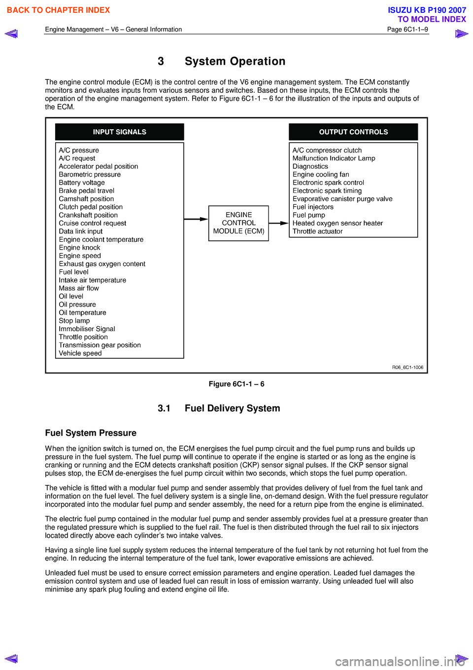
The engine control module (ECM) is the control centre of the V6 engine management system. The ECM constantly
monitors and evaluates inputs from various sensors and switches. Based on these inputs, the ECM controls the
operation of the engine management system. Refer to Figure 6C1-1 – 6 for the illustration of the inputs and outputs of
the ECM.
Figure 6C1-1 – 6
3.1 Fuel Delivery System
Fuel System Pressure
W hen the ignition switch is turned on, the ECM energises the fuel pump circuit and the fuel pump runs and builds up
pressure in the fuel system. The fuel pump will continue to operate if the engine is started or as long as the engine is
cranking or running and the ECM detects crankshaft position (CKP) sensor signal pulses. If the CKP sensor signal
pulses stop, the ECM de-energises the fuel pump circuit within two seconds, which stops the fuel pump operation.
The vehicle is fitted with a modular fuel pump and sender assembly that provides delivery of fuel from the fuel tank and
information on the fuel level. The fuel delivery system is a single line, on-demand design. W ith the fuel pressure regulator
incorporated into the modular fuel pump and sender assembly, the need for a return pipe from the engine is eliminated.
The electric fuel pump contained in the modular fuel pump and sender assembly provides fuel at a pressure greater than
the regulated pressure which is supplied to the fuel rail. The fuel is then distributed through the fuel rail to six injectors
located directly above each cylinder’s two intake valves.
Having a single line fuel supply system reduces the internal temperature of the fuel tank by not returning hot fuel from the
engine. In reducing the internal temperature of the fuel tank, lower evaporative emissions are achieved.
Unleaded fuel must be used to ensure correct emission parameters and engine operation. Leaded fuel damages the
emission control system and use of leaded fuel can result in loss of emission warranty. Using unleaded fuel will also
minimise any spark plug fouling and extend engine oil life.
BACK TO CHAPTER INDEX
TO MODEL INDEX
ISUZU KB P190 2007