2007 ISUZU KB P190 Fuel line
[x] Cancel search: Fuel linePage 3770 of 6020
Automatic Transmission – 4L60E – General Information Page 7C1–10
Transmission Control Module Operation
The TCM processes data every 10 milliseconds from various sensors, such as throttle position, vehicle speed, gear
range, temperature, engine load and other inputs. The TCM compares all its various inputs with the internal programming
and calibration of the TCM using this data, a signal is transmitted to the valve body shift solenoids, which activate the
shift valves for precise shift control. Shift points are therefore precisely controlled and are identical from vehicle to vehic le.
The TCM also control torque converter clutch apply and release.
Shift feel is also electronically controlled by the TCM, by signals sent to the variable force solenoid, which controls fluid
line pressure and it is this pressure that precisely determines how the shifts will feel. In this way, the TCM electronically
synchronises the engine and transmission into a single integrated powertrain system for optimum performance, shift
timing, fuel efficiency and emission control.
3.2 TCM Wiring Diagrams
For details of the transmission control module (TCM) wiring diagrams, refer to 8A Electrical-Body and Chassis.
BACK TO CHAPTER INDEX
TO MODEL INDEX
ISUZU KB P190 2007
Page 3795 of 6020
Automatic Transmission – 4L60E – Electrical Diagnosis Page 7C2–9
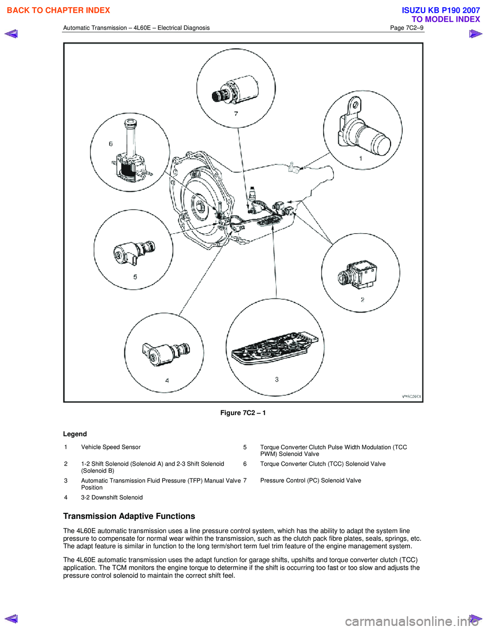
Figure 7C2 – 1
Legend
1 Vehicle Speed Sensor 5 Torque Converter Clutch Pulse Width Modulation (TCC
PWM) Solenoid Valve
2 1-2 Shift Solenoid (Solenoid A) and 2-3 Shift Solenoid (Solenoid B) 6 Torque Converter Clutch (TCC) Solenoid Valve
3
Automatic Transmission Fluid Pressure (TFP) Manual Valve
Position 7 Pressure Control (PC) Solenoid Valve
4 3-2 Downshift Solenoid
Transmission Adaptive Functions
The 4L60E automatic transmission uses a line pressure control system, which has the ability to adapt the system line
pressure to compensate for normal wear within the transmission, such as the clutch pack fibre plates, seals, springs, etc.
The adapt feature is similar in function to the long term/short term fuel trim feature of the engine management system.
The 4L60E automatic transmission uses the adapt function for garage shifts, upshifts and torque converter clutch (TCC)
application. The TCM monitors the engine torque to determine if the shift is occurring too fast or too slow and adjusts the
pressure control solenoid to maintain the correct shift feel.
BACK TO CHAPTER INDEX
TO MODEL INDEX
ISUZU KB P190 2007
Page 3863 of 6020
Automatic Transmission – 4L60E – Electrical Diagnosis Page 7C2–77
Step Action Yes No
When all diagnosis and repairs are completed, check the system for correct operation.
4.25 DTC P0788 – 3-2 Shift Solenoid Control
Circuit High Voltage
DTC Description
This diagnostic procedure supports DTC P0788 3-2 Shift Solenoid (SS) Control Circuit High Voltage.
Circuit Description
The 3-2 shift solenoid (SS) valve is a normally-closed, 3-port, on/off device that controls the 3-2 downshift. The solenoid
attaches to the control valve body within the transmission. The solenoid receives ignition voltage through the ignition 1
circuit. The transmission control module (TCM) controls the solenoid by providing a ground path on the 3-2 shift solenoid
valve control circuit. During a 3-2 downshift, the 2-4 band applies as the 3-4 clutch releases. The TCM varies the timing
between the 3-4 clutch release and the 2-4 band apply depending on the vehicle speed and the throttle position.
When the TCM detects a continuous short to voltage in the 3-2 shift solenoid valve control circuit, then DTC P0788 sets.
DTC P0788 is a type A DTC.
Refer to 2 W iring Diagrams and Connector Chart to aid in diagnosis.
Conditions for Running the DTC
• The system voltage is 10 – 18 V.
• The engine speed is 450 r.p.m. for 5 seconds.
• The engine is not in fuel cut off.
Conditions for Setting the DTC
DTC P0788 sets if the TCM commands the solenoid on and the voltage feedback remains high, battery voltage.
Action Taken When the DTC Sets
• The TCM requests the ECM to illuminate the MIL during the second consecutive trip in which the Conditions for
Setting the DTC are met.
• The TCM commands maximum line pressure.
• The TCM freezes transmission adaptive functions.
• The TCM commands 3rd gear.
• The TCM inhibits TCC engagement.
• At the time of the first failure, the TCM records the operating conditions when the conditions for setting the DTC are
met. The TCM stores this information as a Failure Record.
• At the time of the second failure, the ECM records the operating conditions when the conditions for setting the DTC
are met. The ECM stores this information as a Freeze Frame.
• The TCM stores DTC P0788 in TCM history during the second consecutive trip in which the conditions for setting
the DTC are met.
Conditions for Clearing the DTC
• The ECM turns off the MIL after the fourth consecutive drive trip in which the TCM does not send a MIL illumination
request.
• Tech 2 can clear the DTC.
• The TCM clears the DTC from TCM history if the vehicle completes 40 warm-up cycles without a non-emission
related diagnostic fault occurring.
• The TCM cancels the DTC default actions when the ignition is off long enough to power down the TCM.
BACK TO CHAPTER INDEX
TO MODEL INDEX
ISUZU KB P190 2007
Page 3866 of 6020
Automatic Transmission – 4L60E – Electrical Diagnosis Page 7C2–80
Conditions for Running the DTC
• No DTCs P0122, P0123, P0722, P0723, P0741, P0742, P0751, P0752, P0756, P0757, P0973, P0974, P1810,
P1815, P1816, P2763 or P2764.
• The engine speed is greater than 450 r.p.m. for 5 seconds.
• The engine is not in fuel cut-off.
• The engine torque is 108 Nm – 882 Nm.
• The vehicle speed is 48 – 177 km/h.
• The engine speed is 1,200 – 3,750 r.p.m.
• The speed ratio is 0.70 – 2.25, speed ratio is engine speed divided by the transmission output speed.
• The gear range is D4.
• The commanded gear is not 1st gear.
• The TFT is 20 – 130°C.
• The shift solenoid performance diagnostic counters are zero.
Conditions for Setting the DTC
DTC P0894 sets if the following conditions occur for three TCC cycles.
• The TCC is commanded on for 5 seconds.
• The throttle position is greater than 10 percent.
• The TCC slip speed is 100 – 550 r.p.m. for 10 seconds.
NOTE
The following actions may occur before the DTC
sets, if the:
• TCC is commanded on for 10 seconds, and
• the TCC is at 75 percent duty cycle for
5 seconds, and
• the TP angle is 10 – 99 percent, and
• the transmission slip counter has incremented
to either 1 or 2, out of 3 to increment the fail
counter for the current ignition cycle,
then the following slip conditions and actions may
increment the fail counter for the current ignition
cycle. These conditions must occur sequentially.
Condition 1
If the TCC slip speed is 100 – 550 r.p.m. for 10 seconds, then the TCM will command maximum line pressure and freeze
shift adapts from being updated.
Condition 2
If Condition 1 is met and the TCC slip speed is 100 – 550 r.p.m. for 10 seconds, then the TCM will command the TCC off
for 1.5 seconds.
Condition 3
If Condition 2 is met and the TCC slip speed is 100 – 550 r.p.m. for 10 seconds, then the fail counter on the current
ignition cycle is incremented.
The above slip conditions and actions may be disregarded if the TCC is commanded off at any time, because of a driving
manoeuvre, sudden acceleration or deceleration.
BACK TO CHAPTER INDEX
TO MODEL INDEX
ISUZU KB P190 2007
Page 3933 of 6020
Automatic Transmission – 4L60E – On-vehicle Servicing Page 7C4–20
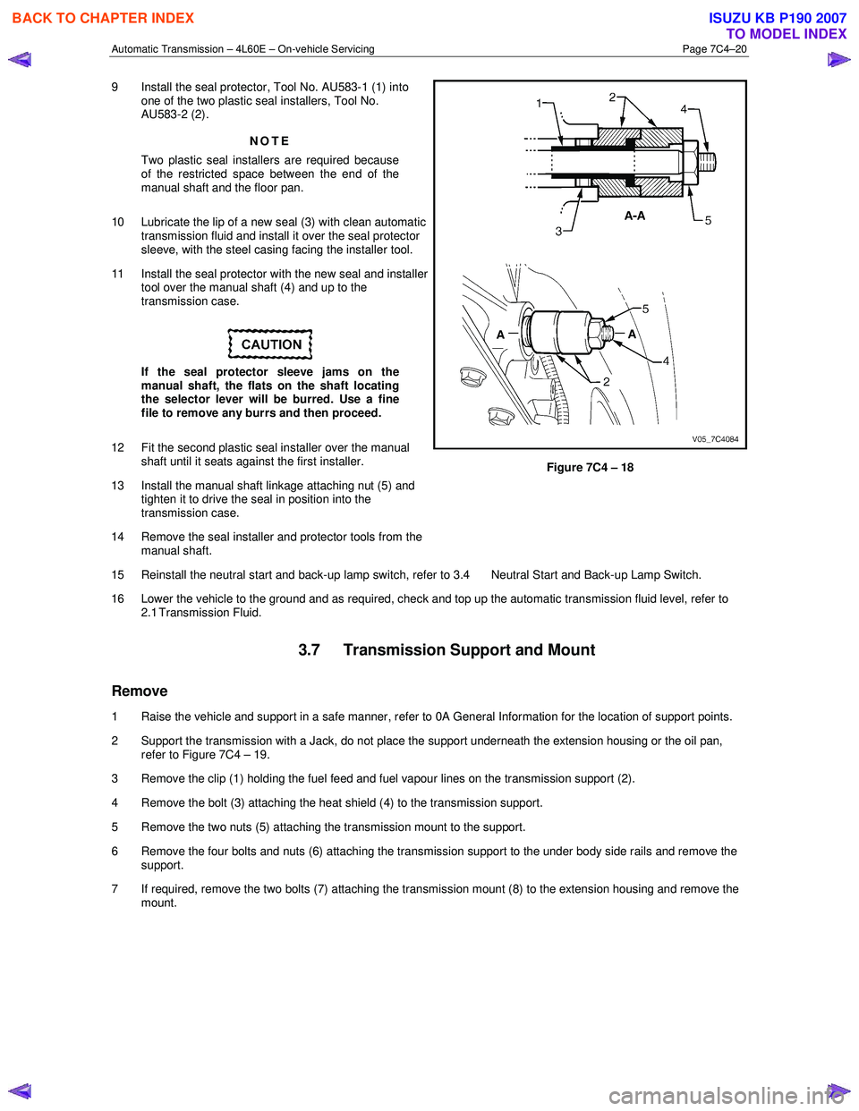
9 Install the seal protector, Tool No. AU583-1 (1) into
one of the two plastic seal installers, Tool No.
AU583-2 (2).
NOTE
Two plastic seal installers are required because
of the restricted space between the end of the
manual shaft and the floor pan.
10 Lubricate the lip of a new seal (3) with clean automatic transmission fluid and install it over the seal protector
sleeve, with the steel casing facing the installer tool.
11 Install the seal protector with the new seal and installer tool over the manual shaft (4) and up to the
transmission case.
If the seal protector sleeve jams on the
manual shaft, the flats on the shaft locating
the selector lever will be burred. Use a fine
file to remove any burrs and then proceed.
12 Fit the second plastic seal installer over the manual shaft until it seats against the first installer.
13 Install the manual shaft linkage attaching nut (5) and tighten it to drive the seal in position into the
transmission case.
14 Remove the seal installer and protector tools from the manual shaft.
Figure 7C4 – 18
15 Reinstall the neutral start and back-up lamp switch, refer to 3.4 Neutral Start and Back-up Lamp Switch.
16 Lower the vehicle to the ground and as required, check and top up the automatic transmission fluid level, refer to 2.1 Transmission Fluid.
3.7 Transmission Support and Mount
Remove
1 Raise the vehicle and support in a safe manner, refer to 0A General Information for the location of support points.
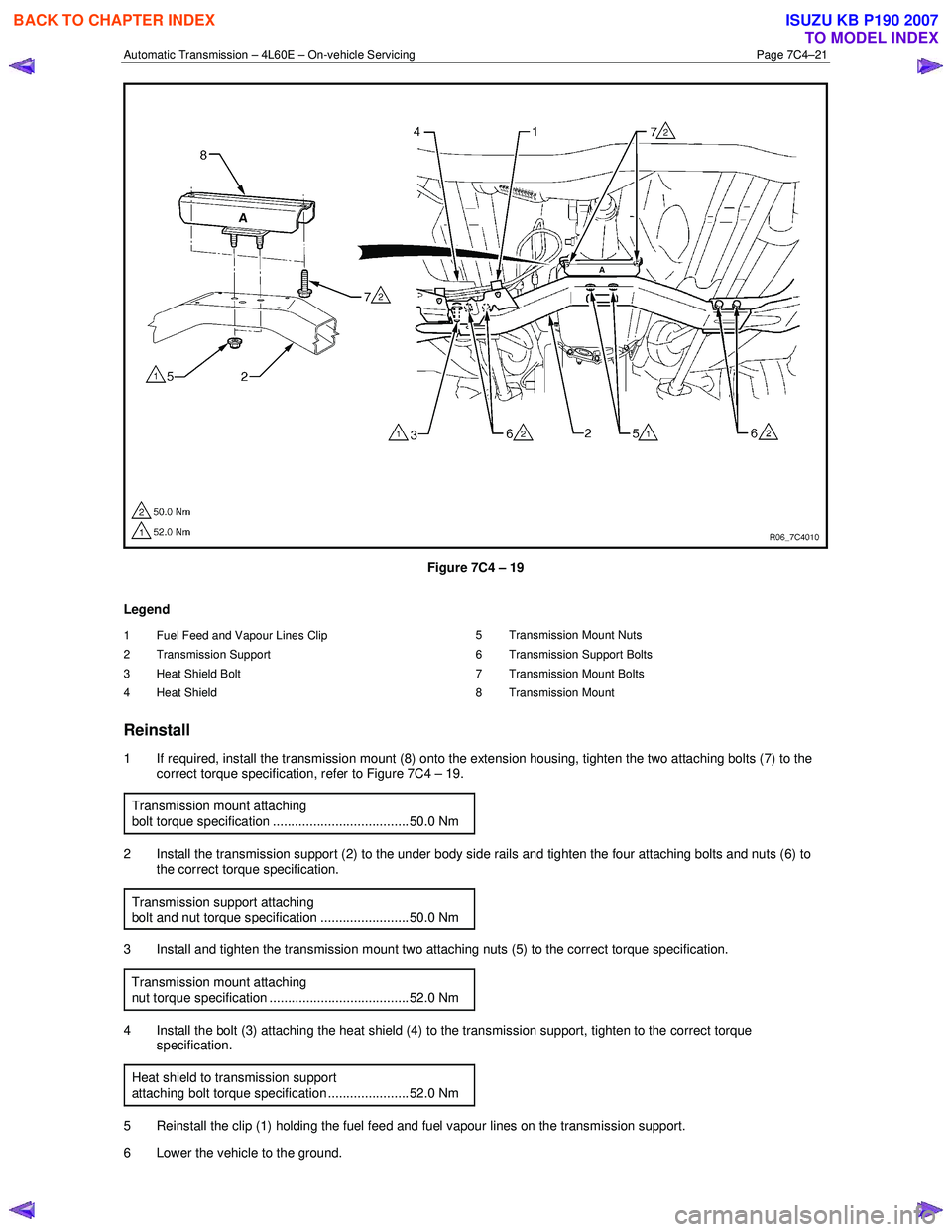
2 Support the transmission with a Jack, do not place the support underneath the extension housing or the oil pan, refer to Figure 7C4 – 19.
3 Remove the clip (1) holding the fuel feed and fuel vapour lines on the transmission support (2).
4 Remove the bolt (3) attaching the heat shield (4) to the transmission support.
5 Remove the two nuts (5) attaching the transmission mount to the support.
6 Remove the four bolts and nuts (6) attaching the transmission support to the under body side rails and remove the support.
7 If required, remove the two bolts (7) attaching the transmission mount (8) to the extension housing and remove the mount.
BACK TO CHAPTER INDEX
TO MODEL INDEX
ISUZU KB P190 2007
Page 3934 of 6020
Automatic Transmission – 4L60E – On-vehicle Servicing Page 7C4–21
Figure 7C4 – 19
Legend
1 Fuel Feed and Vapour Lines Clip
2 Transmission Support
3 Heat Shield Bolt
4 Heat Shield 5 Transmission Mount Nuts
6 Transmission Support Bolts
7 Transmission Mount Bolts
8 Transmission Mount
Reinstall
1 If required, install the transmission mount (8) onto the extension housing, tighten the two attaching bolts (7) to the correct torque specification, refer to Figure 7C4 – 19.
Transmission mount attaching
bolt torque specification ..................................... 50.0 Nm
2 Install the transmission support (2) to the under body side rails and tighten the four attaching bolts and nuts (6) to the correct torque specification.
Transmission support attaching
bolt and nut torque specification ........................ 50.0 Nm
3 Install and tighten the transmission mount two attaching nuts (5) to the correct torque specification.
Transmission mount attaching
nut torque specification ...................................... 52.0 Nm
4 Install the bolt (3) attaching the heat shield (4) to the transmission support, tighten to the correct torque specification.
Heat shield to transmission support
attaching bolt torque specification ...................... 52.0 Nm
5 Reinstall the clip (1) holding the fuel feed and fuel vapour lines on the transmission support.
6 Lower the vehicle to the ground.
BACK TO CHAPTER INDEX
TO MODEL INDEX
ISUZU KB P190 2007
Page 3957 of 6020
Automatic Transmission – 4L60E – On-vehicle Servicing Page 7C4–44
b Starter motor, refer to 6D1-2 Starting System.
b Rear propeller shaft and for 4WD front propeller shaft, refer to 4A Propeller Shaft.
6 On 4WD vehicle, disconnect the harness two clips from the upper side of the transfer case.
7 From within the starter motor access hole, remove the three bolts (2) attaching the torque converter to the flexplate and discard, refer to Figure 7C4 – 62.
8 Remove the transmission support, refer to 3.7 Transmission Support and Mount.
9 Disconnect the fuel and EVAP pipes three brackets and clips, refer to 6C Fuel System – V6.
Before lowering the transmission take care of
the following:
• Do not strain the harness and connector
as the connector pins could be
permanently damaged.
• Ensure the inlet manifold does not hit the
firewall.
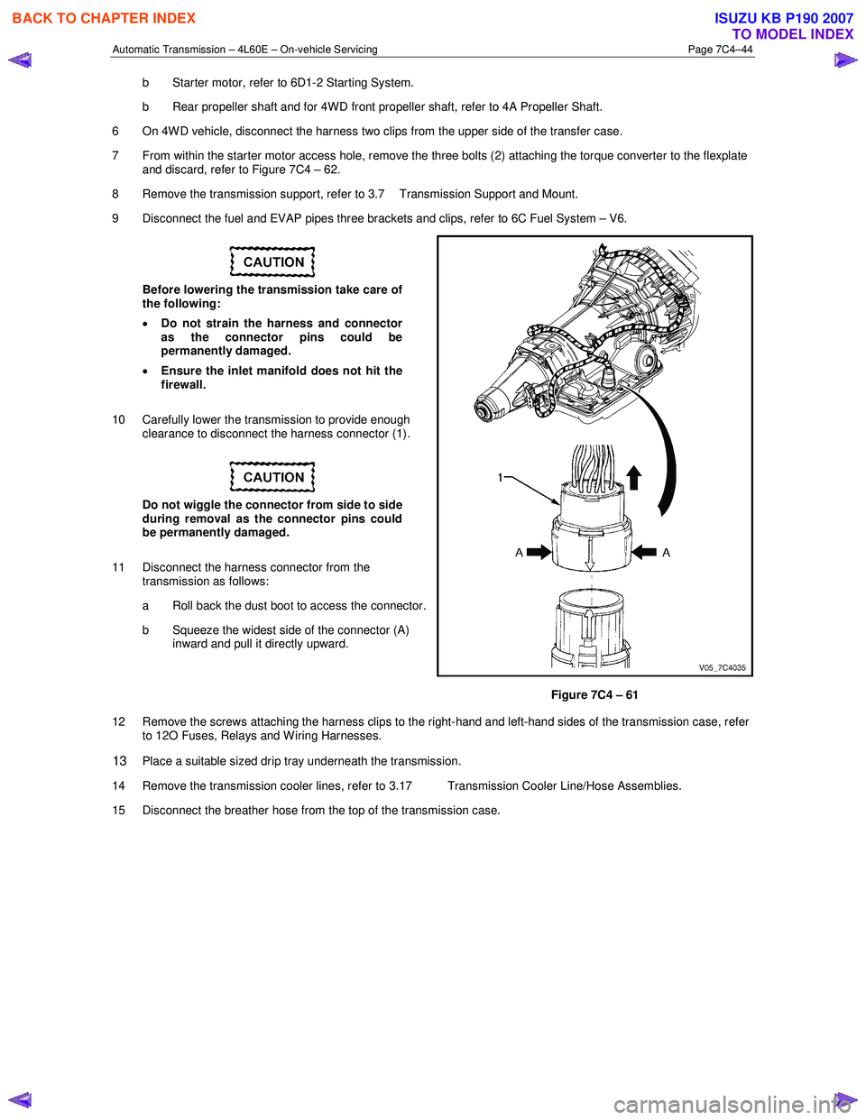
10 Carefully lower the transmission to provide enough clearance to disconnect the harness connector (1).
Do not wiggle the connector from side to side
during removal as the connector pins could
be permanently damaged.
11 Disconnect the harness connector from the transmission as follows:
a Roll back the dust boot to access the connector.
b Squeeze the widest side of the connector (A) inward and pull it directly upward.
Figure 7C4 – 61
12 Remove the screws attaching the harness clips to the right-hand and left-hand sides of the transmission case, refer to 12O Fuses, Relays and W iring Harnesses.
13 Place a suitable sized drip tray underneath the transmission.
14 Remove the transmission cooler lines, refer to 3.17 Transmission Cooler Line/Hose Assemblies.
15 Disconnect the breather hose from the top of the transmission case.
BACK TO CHAPTER INDEX
TO MODEL INDEX
ISUZU KB P190 2007
Page 3960 of 6020
Automatic Transmission – 4L60E – On-vehicle Servicing Page 7C4–47
14 Reconnect the fuel and EVAP pipes three brackets and clips, refer to 6C Fuel System – V6.
15 Reinstall the following components:
a Starter motor, refer to 6D1-2 Starting System.
b Transmission support, refer to 3.7 Transmission Support and Mount.
c Front and centre exhaust assemblies, refer to 6F Exhaust System.
d Rear propeller shaft and for 4WD front propeller shaft, refer to 4A Propeller Shaft.
16 Reconnect the harness connectors to the following: a Vehicle speed sensor, refer to 3.5 Vehicle Speed Sensor.
b Neutral start and back-up switch, refer to 3.4 Neutral Start and Back-up Lamp Switch.
c For the following on 4W D vehicles, refer to 7D Transfer Case and Adaptor Housing:
• neutral switch,
• 2WD – 4WD shift actuator switch,
• speed sensor.
17 Reinstall the selector cable to the transmission external manual shaft linkage, secure the selector cable to the bracket and attach the heat shield to the neutral start and back-up lamp switch, refer to 3.3 Selector Cable
Assembly.
18 Perform a reverse flush of the cooler lines and a flow rate test, refer to 2.2 Reverse Flush and Flow Rate, if either of the following applies:
• the transmission fluid is contaminated,
• the transmission has been replaced,
• the torque converter has been replaced, or
• the transmission oil pump has been replaced.
19 Lower the vehicle to the ground.
20 If required, top up the transmission fluid level (cold).
21 Reconnect the battery ground lead.
22 Start the engine and check for any fluid leaking at the fittings. If a leak is found, stop the engine and rectify the leak.
23 Road test until the transmission has reached operating temperature. Re-check the fluid level and for any fluid leaks, refer to 2.1 Transmission Fluid.
3.19 Transmission Control Module
Remove
1 Ensure the ignition switch is in the OFF position.
2 Disconnect the connector (1) from the transmission control module (TCM) (2) as follows, refer to Figure 7C4 – 63: a remove the securing pin (3),
b press the locking tab and swing the lever (4) to free the connector,
c remove the connector.
3 Remove the four bolts (5) and nuts (6), then the TCM from the mounting bracket (7).
4 If required, remove the two nuts (8) and the mounting bracket from the firewall.
BACK TO CHAPTER INDEX
TO MODEL INDEX
ISUZU KB P190 2007