2007 ISUZU KB P190 Fuel line
[x] Cancel search: Fuel linePage 3253 of 6020
Engine Management – V6 – General Information Page 6C1-1–11
3.2 Air / Fuel Control System
The engine control module (ECM) controls the amount of air and fuel delivered into each of the engine cylinders. Based
on the various ECM inputs, the ECM switches to the following air / fuel control system mode to provide the optimum air /
fuel ratio under all engine operating conditions.
Starting Mode
W hen the ignition switch is moved to the START position and the engine begins to turn, a prime pulse may be injected to
speed starting. As soon as the ECM receives an input signal from the camshaft position (CMP) and crankshaft position
(CKP) sensor and determines which cylinder is in the firing stroke, the ECM applies a pulse width modulated (PW M)
ground to the injector control circuit. The ECM monitors mass air flow, intake air temperature, engine coolant
temperature, and throttle position to determine the required fuel injector on-time required for starting the engine.
Run Mode
The engine switches to run mode when the engine speed reaches 480 rpm after being started. The run mode has two
sub-modes called Open Loop and Closed Loop.
Open Loop Mode
The heated oxygen sensor (HO2S) does not produce a usable signal voltage output until it reaches operating
temperature. Therefore, while the HO2S is below its operating temperature, the ECM switches to open loop mode.
In open loop, the ECM ignores the signals from the HO2S and calculates the required injector pulse width based
primarily on inputs from the mass air flow (MAF), intake air temperature (IAT), and engine coolant temperature sensors.
The system will stay in the open loop mode until the HO2S produce a usable output.
Closed Loop Mode
Once the HO2S reaches operating temperature and starts producing its own signal voltage output, the ECM switches to
the closed loop mode.
In closed loop mode, the ECM initially calculates injector pulse width based on the same sensors used in open loop, and
additionally the ECM uses the oxygen sensor signals to modify and fine tune the fuel pulse width calculations to precisely
maintain the ideal 14.7 to 1 air / fuel ratio.
Acceleration Mode
The ECM monitors and calculates input signals from the accelerator pedal position (APP) and MAF sensor signals to
determine when the vehicle is being accelerated. If the ECM detects the accelerator pedal is depressed and there is a
demand for the vehicle to accelerate, the ECM switches to acceleration mode. In acceleration mode, the ECM increases
the fuel injector on-time to provide more fuel accordingly.
Deceleration Mode
The ECM monitors and calculates input signals from the APP and MAF sensor signals to determine when the vehicle is
being decelerated. If the ECM detects the vehicle is decelerating, the ECM switches to deceleration mode. In
deceleration mode, the ECM decreases the fuel injector on-time, or disables the fuel injectors for short periods, to reduce
exhaust emissions and improve fuel economy.
Fuel Shut-off Mode
To protect the engine from damage or to improve the vehicle's driveability, the ECM switches to the fuel shut-off mode. In
fuel shut-off mode, the ECM performs the following:
• The ECM disables the six fuel injectors under the following conditions:
− Ignition off – to prevent engine dieseling,
− Ignition on but no ignition reference signal – prevents flooding or backfiring,
− At high engine speed – greater than the red line (rev limiter),
− At high vehicle speed – greater than the rated tire speed (vehicle speed limiter), or
− Extended high speed closed throttle coast-down – reduces engine emissions and increases engine braking.
• The ECM selectively disables the appropriate number of fuel injectors when torque management has been enabled.
BACK TO CHAPTER INDEX
TO MODEL INDEX
ISUZU KB P190 2007
Page 3258 of 6020
Engine Management – V6 – General Information Page 6C1-1–16
W hen ECM commands the EVAP valve (1) to open, the fuel
vapours are drawn from the canister line (2) into the intake
manifold where it is consumed in the normal combustion
process.
Figure 6C1-1 – 10
The ECM energises the EVAP valve when the appropriate conditions have been met, such as:
• Engine coolant temperature is less than 20 °C at cold start up and the engine has been running longer than
three minutes and 10 seconds, or
• Engine coolant temperature is greater than 80 °C and the engine has been running longer than five seconds, or
• Engine is not in decel fuel cut-off mode and the throttle opening is less than 96%, or
• The engine is in closed loop fuel mode.
A higher purge rate is used under conditions that are likely to produce large amounts of vapour, when the following
conditions have been met:
• Intake air temperature is greater than 50 °C, or
• Engine coolant temperature is greater than 100 °C, or
• The engine has been running for greater than 15 minutes.
The EVAP purge PW M duty cycle varies according to operating conditions determined by mass air flow, fuel trim and
intake air temperature. The EVAP canister purge valve is re-enabled when throttle position angle decreases below 96%.
For further information on the evaporative emission control system, refer to 6C Fuel System.
Engine Ventilation System
The engine ventilation system contains a Positive crankcase
ventilation (PCV) valve (1) located in the right-hand
camshaft cover. A hose is routed from the PCV valve to
each side of the intake manifold which provides an even
distribution of crankcase fumes, thereby improving spark
plug reliability and a reduction in emissions.
A breather pipe is routed from the intake manifold to the left-
hand camshaft cover and provides fresh filtered air from the
intake duct to the engine.
For further information of the engine ventilation system,
refer to 6A1 Engine Mechanical – V6.
Figure 6C1-1 – 11
BACK TO CHAPTER INDEX
TO MODEL INDEX
ISUZU KB P190 2007
Page 3277 of 6020
Engine Management – V6 – General Information Page 6C1-1–35
5 Abbreviations and Glossary of
Te r m s
Abbreviations and terms used in this Section are listed below in alphabetical order with an explanation of the
abbreviation or term.
Abbreviation Description
A/C Air-conditioning
AC Alternating Current – An electrical current where the polarity is constantly changing between positive and
negative
A/F Air / Fuel (A/F Ratio)
Analogue Signal An electrical signal that constantly varies in voltage within a given parameter
Barometric Pressure Barometric absolute pressure (atmospheric pressure)
CAN Controller Area Network – A type of serial data for communication between electronic devices.
Catalytic Converter
A muffler-shaped device fitted in the exhaust system, usually close to the engine. Through chemical reaction,
a catalytic converter converts harmful gases produced by the combustion process such as HC, CO, and NOx,
into environmentally safe water vapour, carbon dioxide, and nitrogen.
CKT Circuit
Closed Loop A fuel control mode of operation that uses the signal from the exhaust oxygen sensor(s), to control the air / fuel
ratio precisely at a 14.7 to 1 ratio. This allows maximum efficiency of the catalytic converter.
CO Carbon Monoxide. One of the gases produced by the engine combustion process.
DC Direct Current
Digital Signal An electrical signal that is either on or off.
DLC
Data Link Connector. Used at the assembly plant to evaluate the engine management system. For service, it
allows the use of Tech 2 in performing system checks.
DLC Data Stream An output from the ECM initiated by Tech 2 and transmitted via the Data Link Connector(DLC).
DMM (10 M Ω) Digital Multimeter. A multipurpose meter that has capability of measuring voltage, current flow and resistance.
A digital multimeter has an input impedance of 10 M Ω (megohms), which means they draw very little power
from the device under test, they are very accurate and will not damage delicate electronic components
Driver An electronic device, usually a power transistor, that operates as an electrical switch.
DTC
Diagnostic Trouble Code. If a fault occurs in the engine management system, the ECM may set a four digit
diagnostic trouble code (DTC) which represents the fault condition. Tech 2 is used to interface with the ECM
and access the DTC(s). The ECM may also operate the malfunction indicator lamp in the instrument cluster.
Duty Cycle The time, in percentage, that a circuit is on versus off.
ECT Sensor
Engine Coolant Temperature sensor. A device that provides a variable voltage to the ECM based on the
temperature of the engine coolant.
EEPROM Electrically Erasable Programmable Read Only Memory. A type of read only memory (ROM) that can be
electrically programmed, erased and reprogrammed using Tech 2. Also referred to as Flash Memory
EMI or Electrical
Noise An unwanted signal interfering with a required signal. A common example is the effect of high voltage power
lines on an AM radio.
Engine Braking A condition where the engine is used to slow the vehicle on closed throttle or low gear.
EPROM Erasable Programmable Read Only Memory. A type of Read Only Memory (ROM) that can be erased with
ultraviolet light and then reprogrammed.
ESD Electrostatic Discharge. The discharge of static electricity which has built up on an insulated material
EVAP
Evaporative emission control system. Used to prevent fuel vapours from the fuel tank from entering into the
atmosphere. The vapours are stored in a canister that contains an activated charcoal element. The fuel
vapours are purged from the canister into the manifold to be burned in the engine.
GM LAN General Motors Local Area Network - A type of serial data for communication between electronic devices.
Fuse
A thin metal strip which melts when excessive current flows through it, creating an open circuit and protecting
a circuit from damage.
HC Hydrocarbon. Result of unburned fuel produced by incomplete combustion.
Heavy Throttle Approximately 3/4 of accelerator pedal travel (75% throttle position)
IAT Sensor
Intake Air Temperature sensor. A device that provides a variable voltage to the ECM based on the
temperature of air entering the intake system.
Ideal Mixture The air / fuel ratio which provides the best performance, while maintaining maximum conversion of exhaust
emissions, typically 14.7 to 1 on spark ignition engines
IGN Ignition
Inputs Information from sensors (MAF, TP, etc.) and switches (A/C request, etc.) used by the ECM to determine how
to control its outputs.
BACK TO CHAPTER INDEX
TO MODEL INDEX
ISUZU KB P190 2007
Page 3365 of 6020
Engine Management – V6 – Diagnostics Page 6C1-2–87
Step Action Yes No
4 1 Disconnect the appropriate HO2S wiring connector.
2 Switch on the ignition with the engine not running.
3 Using a digital multimeter, measure the voltage between the HO2S reference signal circuit and low reference circuit.
Does the multimeter display 350 – 550 mV? Go to Step 7 Go to Step 5
5 1 Test the reference signal circuit of the HO2S for a high
resistance, open circuit, short to ground or short to voltage fault
condition. Refer to 8A Electrical - Body and Chassis for
information on electrical fault diagnosis.
W as any fault found and rectified? Go to Step 10 Go to Step 6
6 1 Test the low reference circuit of the HO2S for a high resistance,
open circuit, short to ground or short to voltage fault condition.
Refer to 8A Electrical - Body and Chassis for information on
electrical fault diagnosis.
W as any fault found and rectified? Go to Step 10 Go to Step 9
7 1 Test or inspect for the following conditions that may cause the
HO2S to detect an incorrect air / fuel mixture:
− lean or rich fuel injector fuel delivery,
− restricted air intake system,
− contaminated fuel,
− low fuel line pressure,
− exhaust leak near the HO2S, and
− leak in the crankcase or vacuum line.
W as any fault found and rectified? Go to Step 10 Go to Step 8
8 1 Replace the appropriate HO2S. Refer to 6C1-3 Engine
Management – V6 – Service Operations.
W as the repair completed? Go to Step 10 —
9 1 Replace the ECM. Refer to 6C1-3 Engine Management – V6 –
Service Operations.
W as the repair completed? Go to Step 10 —
10 1 Using Tech 2, clear the DTCs.
2 Switch off the ignition for 30 seconds.
3 Start the engine.
4 Operate the vehicle within the conditions for running the DTC.
Does any HO2S reference circuit DTC fail this ignition cycle? Go to Step 2 Go to Step 11
11 1 Using Tech 2, select the DTC display function.
Does Tech 2 display any DTCs? Go to the
appropriate DTC
Table in this Section System OK
When all diagnosis and repairs are completed, check the system for correct operation.
7.11 DTC P0133 or P0153
DTC Descriptors
This diagnostic procedure supports the following DTCs:
• DTC P0133 – HO2S Circuit Slow Response – Bank 1 Sensor 1
BACK TO CHAPTER INDEX
TO MODEL INDEX
ISUZU KB P190 2007
Page 3492 of 6020
Engine Management – V6 – Diagnostics Page 6C1-2–214
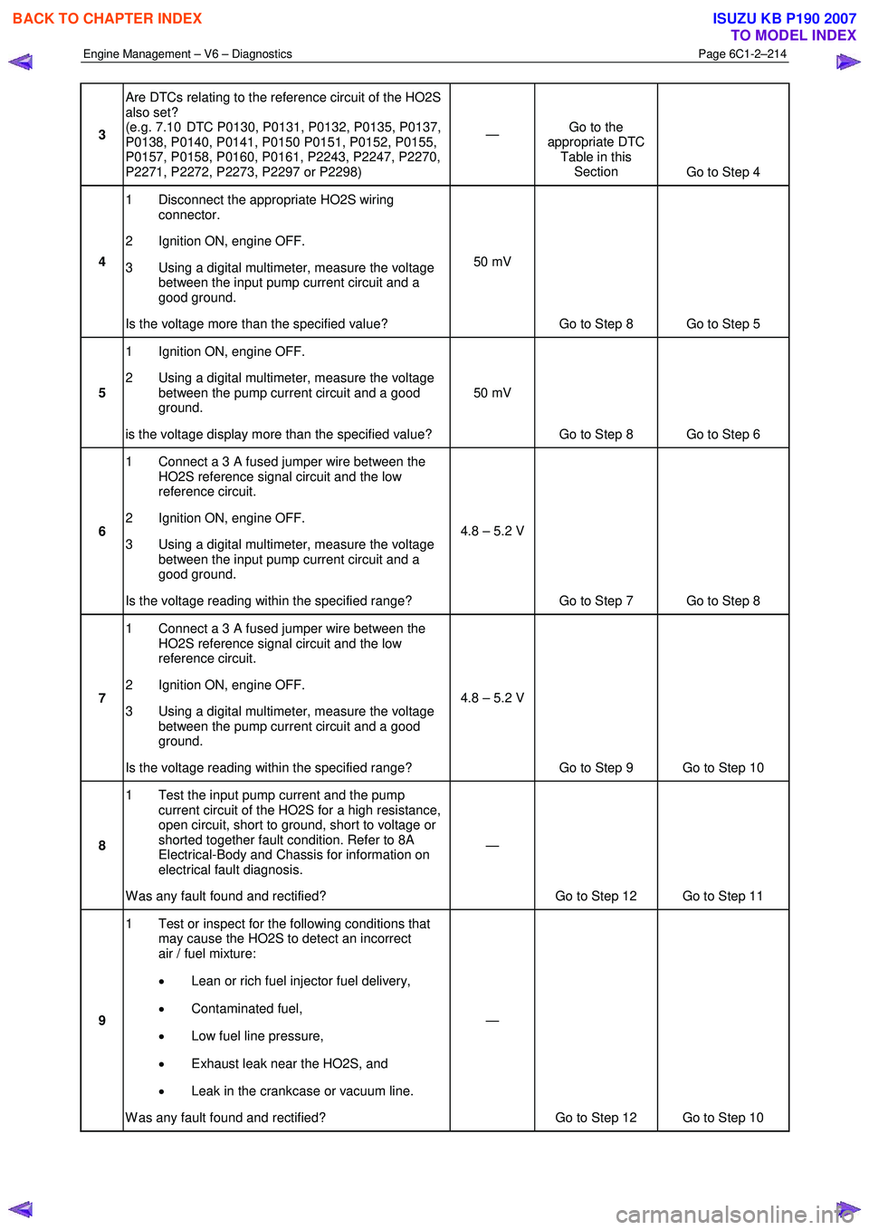
3 Are DTCs relating to the reference circuit of the HO2S
also set?
(e.g. 7.10 DTC P0130, P0131, P0132, P0135, P0137,
P0138, P0140, P0141, P0150 P0151, P0152, P0155,
P0157, P0158, P0160, P0161, P2243, P2247, P2270,
P2271, P2272, P2273, P2297 or P2298) —
Go to the
appropriate DTC Table in this Section Go to Step 4
4 1 Disconnect the appropriate HO2S wiring
connector.
2 Ignition ON, engine OFF.
3 Using a digital multimeter, measure the voltage between the input pump current circuit and a
good ground.
Is the voltage more than the specified value? 50 mV
Go to Step 8 Go to Step 5
5 1 Ignition ON, engine OFF.
2 Using a digital multimeter, measure the voltage between the pump current circuit and a good
ground.
is the voltage display more than the specified value? 50 mV
Go to Step 8 Go to Step 6
6 1 Connect a 3 A fused jumper wire between the
HO2S reference signal circuit and the low
reference circuit.
2 Ignition ON, engine OFF.
3 Using a digital multimeter, measure the voltage between the input pump current circuit and a
good ground.
Is the voltage reading within the specified range? 4.8 – 5.2 V
Go to Step 7 Go to Step 8
7 1 Connect a 3 A fused jumper wire between the
HO2S reference signal circuit and the low
reference circuit.
2 Ignition ON, engine OFF.
3 Using a digital multimeter, measure the voltage between the pump current circuit and a good
ground.
Is the voltage reading within the specified range? 4.8 – 5.2 V
Go to Step 9 Go to Step 10
8 1 Test the input pump current and the pump
current circuit of the HO2S for a high resistance,
open circuit, short to ground, short to voltage or
shorted together fault condition. Refer to 8A
Electrical-Body and Chassis for information on
electrical fault diagnosis.
W as any fault found and rectified? —
Go to Step 12 Go to Step 11
9 1 Test or inspect for the following conditions that
may cause the HO2S to detect an incorrect
air / fuel mixture:
• Lean or rich fuel injector fuel delivery,
• Contaminated fuel,
• Low fuel line pressure,
• Exhaust leak near the HO2S, and
• Leak in the crankcase or vacuum line.
W as any fault found and rectified? —
Go to Step 12 Go to Step 10
BACK TO CHAPTER INDEX
TO MODEL INDEX
ISUZU KB P190 2007
Page 3529 of 6020
Engine Management – V6 – Service Operations Page 6C1-3–5
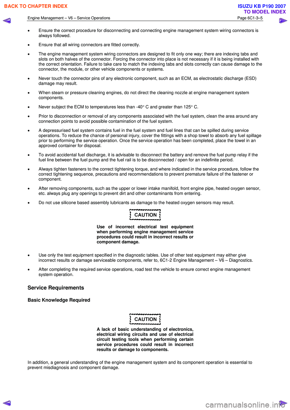
• Ensure the correct procedure for disconnecting and connecting engine management system wiring connectors is
always followed.
• Ensure that all wiring connectors are fitted correctly.
• The engine management system wiring connectors are designed to fit only one way; there are indexing tabs and
slots on both halves of the connector. Forcing the connector into place is not necessary if it is being installed with
the correct orientation. Failure to take care to match the indexing tabs and slots correctly can cause damage to the
connector, the module, or other vehicle components or systems.
• Never touch the connector pins of any electronic component, such as an ECM, as electrostatic discharge (ESD)
damage may result.
• W hen steam or pressure cleaning engines, do not direct the cleaning nozzle at engine management system
components.
• Never subject the ECM to temperatures less than -40 ° C and greater than 125 ° C.
• Prior to disconnection or removal of any components associated with the fuel system, clean the area around any
connection points to avoid possible contamination of the fuel system.
• A depressurised fuel system contains fuel in the fuel system and fuel lines that can be spilled during service
operations. To reduce the chance of personal injury, cover the fittings with a shop towel to absorb any fuel spillage
prior to performing the service operation. Once the service operation has been completed, place the towel in an
approved container for disposal.
• To avoid accidental fuel discharge, it is advisable to disconnect the battery and remove the fuel pump relay if the
fuel line between the fuel pump and the fuel rail is to be disconnected / open for an indefinite period.
• Always tighten fasteners to the correct tightening torque, and where indicated in the service procedure, follow the
correct tightening sequence, precautions and recommendations to prevent premature failure of the fastener or
component.
• After removing components, such as the upper or lower intake manifold, front engine pipe, heated oxygen sensor,
etc. always plug any openings to prevent dirt and other contaminants from entering.
• Do not use silicone based assembly lubricants as damage to the heated oxygen sensors may result.
Use of incorrect electrical test equipment
when performing engine management service
procedures could result in incorrect results or
component damage.
• Use only the test equipment specified in the diagnostic tables. Use of other test equipment may either give
incorrect results or damage serviceable components, refer to, 6C1-2 Engine Management – V6 – Diagnostics.
• After completing the required service operations, road test the vehicle to ensure correct engine management
system operation.
Service Requirements
Basic Knowledge Required
A lack of basic understanding of electronics,
electrical wiring circuits and use of electrical
circuit testing tools when performing certain
service procedures could result in incorrect
results or damage to components.
In addition, a general understanding of the engine management system and its component operation is essential to
prevent misdiagnosis and component damage.
BACK TO CHAPTER INDEX
TO MODEL INDEX
ISUZU KB P190 2007
Page 3530 of 6020
Engine Management – V6 – Service Operations Page 6C1-3–6
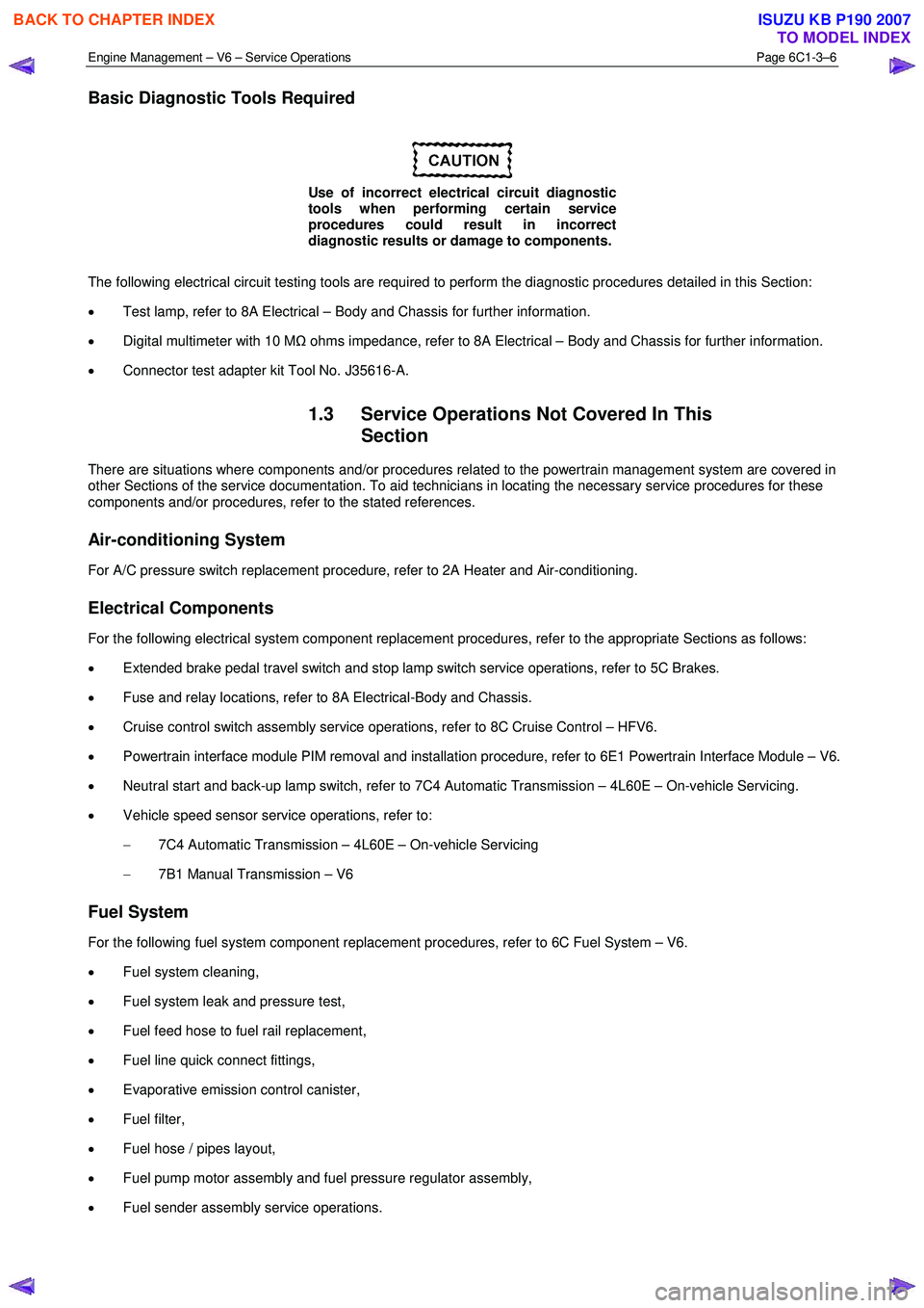
Basic Diagnostic Tools Required
Use of incorrect electrical circuit diagnostic
tools when performing certain service
procedures could result in incorrect
diagnostic results or damage to components.
The following electrical circuit testing tools are required to perform the diagnostic procedures detailed in this Section:
• Test lamp, refer to 8A Electrical – Body and Chassis for further information.
• Digital multimeter with 10 M Ω ohms impedance, refer to 8A Electrical – Body and Chassis for further information.
• Connector test adapter kit Tool No. J35616-A.
1.3 Service Operations Not Covered In This
Section
There are situations where components and/or procedures related to the powertrain management system are covered in
other Sections of the service documentation. To aid technicians in locating the necessary service procedures for these
components and/or procedures, refer to the stated references.
Air-conditioning System
For A/C pressure switch replacement procedure, refer to 2A Heater and Air-conditioning.
Electrical Components
For the following electrical system component replacement procedures, refer to the appropriate Sections as follows:
• Extended brake pedal travel switch and stop lamp switch service operations, refer to 5C Brakes.
• Fuse and relay locations, refer to 8A Electrical-Body and Chassis.
• Cruise control switch assembly service operations, refer to 8C Cruise Control – HFV6.
• Powertrain interface module PIM removal and installation procedure, refer to 6E1 Powertrain Interface Module – V6.
• Neutral start and back-up lamp switch, refer to 7C4 Automatic Transmission – 4L60E – On-vehicle Servicing.
• Vehicle speed sensor service operations, refer to:
− 7C4 Automatic Transmission – 4L60E – On-vehicle Servicing
− 7B1 Manual Transmission – V6
Fuel System
For the following fuel system component replacement procedures, refer to 6C Fuel System – V6.
• Fuel system cleaning,
• Fuel system leak and pressure test,
• Fuel feed hose to fuel rail replacement,
• Fuel line quick connect fittings,
• Evaporative emission control canister,
• Fuel filter,
• Fuel hose / pipes layout,
• Fuel pump motor assembly and fuel pressure regulator assembly,
• Fuel sender assembly service operations.
BACK TO CHAPTER INDEX
TO MODEL INDEX
ISUZU KB P190 2007
Page 3553 of 6020
Engine Management – V6 – Service Operations Page 6C1-3–29
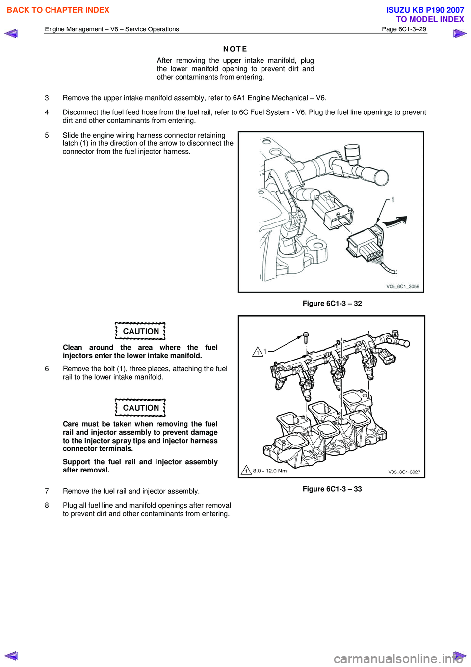
NOTE
After removing the upper intake manifold, plug
the lower manifold opening to prevent dirt and
other contaminants from entering.
3 Remove the upper intake manifold assembly, refer to 6A1 Engine Mechanical – V6.
4 Disconnect the fuel feed hose from the fuel rail, refer to 6C Fuel System - V6. Plug the fuel line openings to prevent dirt and other contaminants from entering.
5 Slide the engine wiring harness connector retaining latch (1) in the direction of the arrow to disconnect the
connector from the fuel injector harness.
Figure 6C1-3 – 32
Clean around the area where the fuel
injectors enter the lower intake manifold.
6 Remove the bolt (1), three places, attaching the fuel rail to the lower intake manifold.
Care must be taken when removing the fuel
rail and injector assembly to prevent damage
to the injector spray tips and injector harness
connector terminals.
Support the fuel rail and injector assembly
after removal.
7 Remove the fuel rail and injector assembly.
8 Plug all fuel line and manifold openings after removal to prevent dirt and other contaminants from entering.
Figure 6C1-3 – 33
BACK TO CHAPTER INDEX
TO MODEL INDEX
ISUZU KB P190 2007