2007 ISUZU KB P190 Fuel line
[x] Cancel search: Fuel linePage 3979 of 6020
TRANSMISSION CONTROL SYSTEM (AW30–40LE) 7A2-13
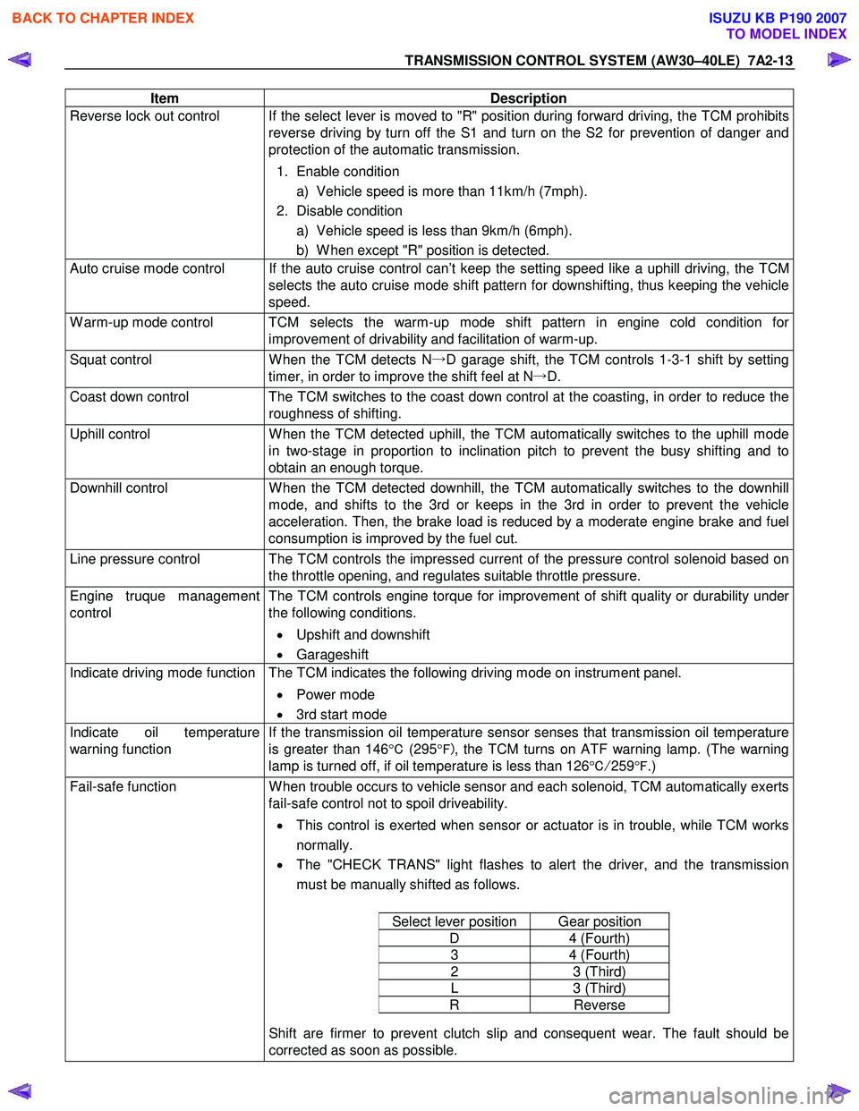
Item Description
Reverse lock out control If the select lever is moved to "R" position during forward driving, the TCM prohibits
reverse driving by turn off the S1 and turn on the S2 for prevention of danger and
protection of the automatic transmission.
1. Enable condition a) Vehicle speed is more than 11km/h (7mph).
2. Disable condition a) Vehicle speed is less than 9km/h (6mph).
b) W hen except "R" position is detected.
Auto cruise mode control If the auto cruise control can’t keep the setting speed like a uphill driving, the TCM selects the auto cruise mode shift pattern for downshifting, thus keeping the vehicle
speed.
W arm-up mode control TCM selects the warm-up mode shift pattern in engine cold condition for improvement of drivability and facilitation of warm-up.
Squat control W hen the TCM detects N→D garage shift, the TCM controls 1-3-1 shift by setting
timer, in order to improve the shift feel at N →D.
Coast down control The TCM switches to the coast down control at the coasting, in order to reduce the
roughness of shifting.
Uphill control W hen the TCM detected uphill, the TCM automatically switches to the uphill mode
in two-stage in proportion to inclination pitch to prevent the busy shifting and to
obtain an enough torque.
Downhill control W hen the TCM detected downhill, the TCM automatically switches to the downhill
mode, and shifts to the 3rd or keeps in the 3rd in order to prevent the vehicle
acceleration. Then, the brake load is reduced by a moderate engine brake and fuel
consumption is improved by the fuel cut.
Line pressure control The TCM controls the impressed current of the pressure control solenoid based on the throttle opening, and regulates suitable throttle pressure.
Engine truque management
control The TCM controls engine torque for improvement of shift quality or durability under
the following conditions.
• Upshift and downshift
• Garageshift
Indicate driving mode function The TCM indicates the following driving mode on instrument panel.
• Power mode
• 3rd start mode
Indicate oil temperature
warning function If the transmission oil temperature sensor senses that transmission oil temperature
is greater than 146 °C (295 °F) , the TCM turns on ATF warning lamp. (The warning
lamp is turned off, if oil temperature is less than 126 °C/ 259 °F .)
Fail-safe function W hen trouble occurs to vehicle sensor and each solenoid, TCM automatically exerts
fail-safe control not to spoil driveability.
• This control is exerted when sensor or actuator is in trouble, while TCM works
normally.
• The "CHECK TRANS" light flashes to alert the driver, and the transmission
must be manually shifted as follows.
Select lever position Gear position
D 4 (Fourth)
3 4 (Fourth)
2 3 (Third)
L 3 (Third)
R Reverse
Shift are firmer to prevent clutch slip and consequent wear. The fault should be
corrected as soon as possible.
BACK TO CHAPTER INDEX
TO MODEL INDEX
ISUZU KB P190 2007
Page 4026 of 6020
7A2-60 TRANSMISSION CONTROL SYSTEM (AW30–40LE)
(2) Select position switches is not detecting failure o
r
not deciding failure.
(3) Input revolution sensor is not detecting failure o
r
not deciding failure.
(4) Output revolution calculated by input revolution is more than 300rpm.
(5) If input revolution signal pulse count is more than 13 ×500, any pulse is not detected from output
revolution sensor.
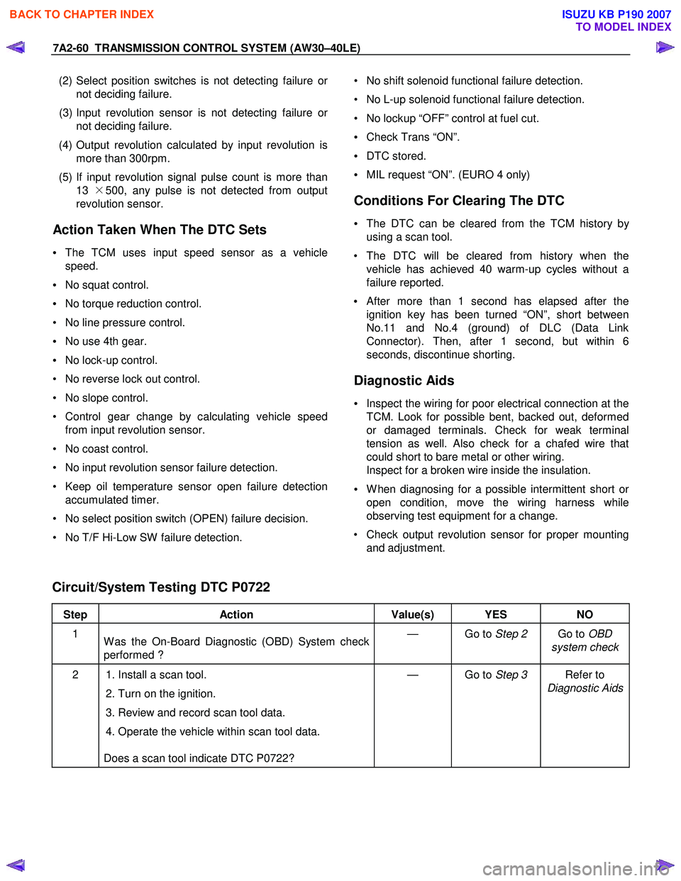
Action Taken When The DTC Sets
• The TCM uses input speed sensor as a vehicle
speed.
• No squat control.
• No torque reduction control.
• No line pressure control.
• No use 4th gear.
• No lock-up control.
• No reverse lock out control.
• No slope control.
• Control gear change by calculating vehicle speed from input revolution sensor.
• No coast control.
• No input revolution sensor failure detection.
• Keep oil temperature sensor open failure detection accumulated timer.
• No select position switch (OPEN) failure decision.
• No T/F Hi-Low SW failure detection.
• No shift solenoid functional failure detection.
• No L-up solenoid functional failure detection.
• No lockup “OFF” control at fuel cut.
• Check Trans “ON”.
• DTC stored.
• MIL request “ON”. (EURO 4 only)
Conditions For Clearing The DTC
• The DTC can be cleared from the TCM history by
using a scan tool.
• The DTC will be cleared from history when the vehicle has achieved 40 warm-up cycles without a
failure reported.
•
After more than 1 second has elapsed after the
ignition key has been turned “ON”, short between
No.11 and No.4 (ground) of DLC (Data Link
Connector). Then, after 1 second, but within 6
seconds, discontinue shorting.
Diagnostic Aids
• Inspect the wiring for poor electrical connection at the
TCM. Look for possible bent, backed out, deformed
or damaged terminals. Check for weak terminal
tension as well. Also check for a chafed wire that
could short to bare metal or other wiring.
Inspect for a broken wire inside the insulation.
• W hen diagnosing for a possible intermittent short o
r
open condition, move the wiring harness while
observing test equipment for a change.
• Check output revolution sensor for proper mounting and adjustment.
Circuit/System Testing DTC P0722
Step Action Value(s) YES NO
1
W as the On-Board Diagnostic (OBD) System check
performed ? — Go to
Step 2 Go to OBD
system check
2 1. Install a scan tool.
2. Turn on the ignition.
3. Review and record scan tool data.
4. Operate the vehicle within scan tool data.
Does a scan tool indicate DTC P0722? — Go to
Step 3 Refer to
Diagnostic Aids
BACK TO CHAPTER INDEX
TO MODEL INDEX
ISUZU KB P190 2007
Page 4337 of 6020
TRANSMISSION CONTROL SYSTEM (JR405E) 7A2-53
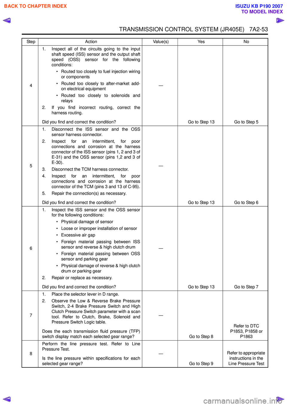
41. Inspect all of the circuits going to the input
shaft speed (ISS) sensor and the output shaft
speed (OSS) sensor for the following
conditions:
• Routed too closely to fuel injection wiring or components
• Routed too closely to after-market add- on electrical equipment
• Routed too closely to solenoids and relays
2. If you find incorrect routing, correct the harness routing.
Did you find and correct the condition? —
Go to Step 13 Go to Step 5
5 1. Disconnect the ISS sensor and the OSS
sensor harness connector.
2. Inspect for an intermittent, for poor connections and corrosion at the harness
connector of the ISS sensor (pins 1, 2 and 3 of
E-31) and the OSS sensor (pins 1,2 and 3 of
E-30).
3. Disconnect the TCM harness connector.
4. Inspect for an intermittent, for poor connections and corrosion at the harness
connector of the TCM (pins 3 and 13 of C-95).
5. Repair the connection(s) as necessary.
Did you find and correct the condition? —
Go to Step 13 Go to Step 6
6 1. Inspect the ISS sensor and the OSS sensor
for the following conditions:
• Physical damage of sensor
• Loose or improper installation of sensor
• Excessive air gap
• Foreign material passing between ISS sensor and reverse & high clutch drum
• Foreign material passing between OSS sensor and parking gear
• Physical damage of reverse & high clutch drum or parking gear
2. Repair or replace as necessary.
Did you find and correct the condition? —
Go to Step 13 Go to Step 7
7 1. Place the selector lever in D range.
2. Observe the Low & Reverse Brake Pressure Switch, 2-4 Brake Pressure Switch and High
Clutch Pressure Switch parameter with a scan
tool. Refer to Clutch, Brake, Solenoid and
Pressure Switch Logic table.
Does the each transmission fluid pressure (TFP)
switch display match each selected gear range? —
Go to Step 8 Refer to DTC
P1853, P1858 or P1863
8 Perform the line pressure test. Refer to Line
Pressure Test.
Is the line pressure within specifications for each
selected gear range? —
Go to Step 9 Refer to appropriate
instructions in the
Line Pressure Test
Step
Action Value(s)Yes No
BACK TO CHAPTER INDEX
TO MODEL INDEX
ISUZU KB P190 2007
Page 4385 of 6020
TRANSMISSION CONTROL SYSTEM (JR405E) 7A2-101
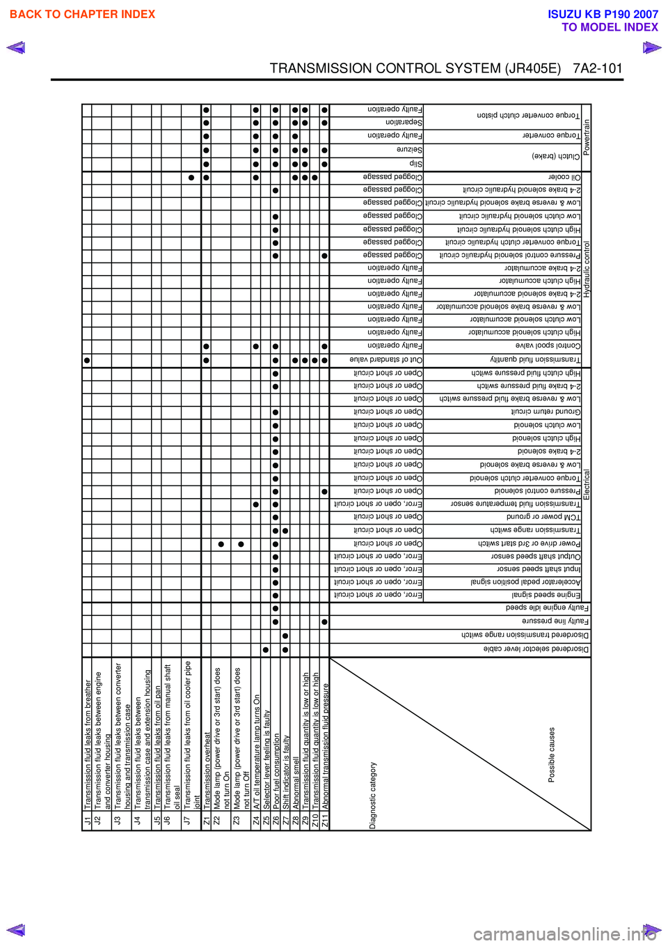
J1Transmission fluid leaks from breatherJ2
Transmission fluid leaks between engine
and converter housing
J3
Transmission fluid leaks between converter
housing and transmission case
J4
Transmission fluid leaks between
transmission case and extension housing
J5 Transmission fluid leaks from oil panJ6
Transmission fluid leaks from manual shaft
oil seal
J7
Transmission fluid leaks from oil cooler pipe
joint
Z1 Transmission overheatZ2
Mode lamp (power drive or 3rd start) does
not turn On
Z3
Mode lamp (power drive or 3rd start) does
not turn Off
Z4 A/T oil temperature lamp turns OnZ5Selector lever feeling is faultyZ6Poor fuel consumptionZ7Shift indicator is faultyZ8Abnormal smellZ9Transmission fluid quantity is low or highZ10 Transmission fluid quantity is low or highZ11Abnormal transmission fluid pressure
Error, open or short circuit
Error, open or short circuit
Error, open or short circuit
Error, open or short circuit
Open or short circuit
Open or short circuit
Open or short circuit
Error, open or short circuit
Open or short circuit
Open or short circuit
Open or short circuit
Open or short circuit
Open or short circuit
Open or short circuit
Open or short circuit
Open or short circuit
Open or short circuit
Open or short circuit
Out of standard value
Faulty operation
Faulty operation
Faulty operation
Faulty operation
Faulty operation
Faulty operation
Faulty operation
Clogged passage
Clogged passage
Clogged passage
Clogged passage
Clogged passage
Clogged passage
Clogged passage
Slip
Seizure
Faulty operation
Separation
Faulty operation
Engine speed signal
Accelerator pedal position signal
Input shaft speed sensor
Output shaft speed sensor
Power drive or 3rd start switch
Transmission range switch
TCM power or ground
Transmission fluid temperature sensor
Pressure control solenoid
Torque converter clutch solenoid
Low & reverse brake solenoid
2-4 brake solenoid
High clutch solenoid
Low clutch solenoid
Ground return circuit
Low & reverse brake fluid pressure switch
2-4 brake fluid pressure switch
High clutch fluid pressure switch
Transmission fluid quantity
Control spool valve
High clutch solenoid accumulator
Low clutch solenoid accumulator
Low & reverse brake solenoid accumulator
2-4 brake solenoid accumulator
High clutch accumulator
2-4 brake accumulator
Pressure control solenoid hydraulic circuit
Torque converter clutch hydraulic circuit
High clutch solenoid hydraulic circuit
Low clutch solenoid hydraulic circuit
Low & reverse brake solenoid hydraulic circuit
2-4 brake solenoid hydraulic circuit
Oil cooler
Torque converter
Clutch (brake)
Torque converter clutch piston
Hydraulic control
Powertrain
Diagnostic category
Possible causes
Electrical
Disordered selector lever cable
Disordered transmission range switch
Faulty line pressure
Faulty engine idle speed
BACK TO CHAPTER INDEX
TO MODEL INDEX
ISUZU KB P190 2007
Page 4731 of 6020
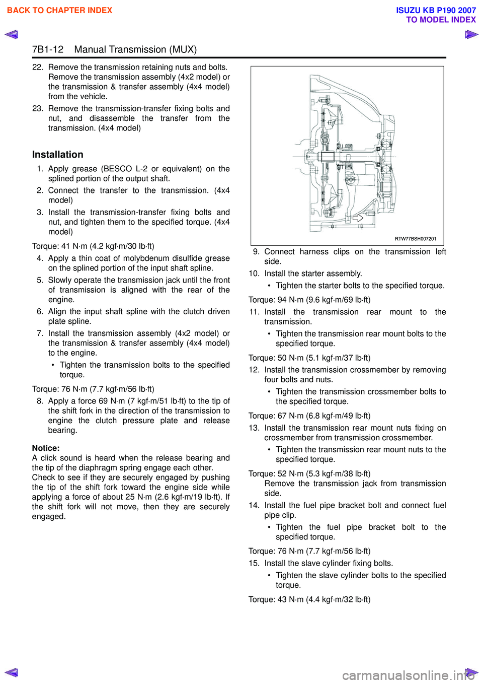
7B1-12 Manual Transmission (MUX)
22. Remove the transmission retaining nuts and bolts.Remove the transmission assembly (4x2 model) or
the transmission & transfer assembly (4x4 model)
from the vehicle.
23. Remove the transmission-transfer fixing bolts and nut, and disassemble the transfer from the
transmission. (4x4 model)
Installation
1. Apply grease (BESCO L-2 or equivalent) on the splined portion of the output shaft.
2. Connect the transfer to the transmission. (4x4 model)
3. Install the transmission-transfer fixing bolts and nut, and tighten them to the specified torque. (4x4
model)
Torque: 41 N ⋅m (4.2 kgf ⋅m/30 lb ⋅ft)
4. Apply a thin coat of molybdenum disulfide grease on the splined portion of the input shaft spline.
5. Slowly operate the transmission jack until the front of transmission is aligned with the rear of the
engine.
6. Align the input shaft spline with the clutch driven plate spline.
7. Install the transmission assembly (4x2 model) or the transmission & transfer assembly (4x4 model)
to the engine.
• Tighten the transmission bolts to the specified torque.
Torque: 76 N ⋅m (7.7 kgf ⋅m/56 lb ⋅ft)
8. Apply a force 69 N ⋅m (7 kgf ⋅m/51 lb ⋅ft) to the tip of
the shift fork in the direction of the transmission to
engine the clutch pressure plate and release
bearing.
Notice:
A click sound is heard when the release bearing and
the tip of the diaphragm spring engage each other.
Check to see if they are securely engaged by pushing
the tip of the shift fork toward the engine side while
applying a force of about 25 N ⋅m (2.6 kgf ⋅m/19 lb ⋅ft). If
the shift fork will not move, then they are securely
engaged. 9. Connect harness clips on the transmission left
side.
10. Install the starter assembly.
• Tighten the starter bolts to the specified torque.
Torque: 94 N ⋅m (9.6 kgf ⋅m/69 lb ⋅ft)
11. Install the transmission rear mount to the transmission.
• Tighten the transmission rear mount bolts to the specified torque.
Torque: 50 N ⋅m (5.1 kgf ⋅m/37 lb ⋅ft)
12. Install the transmission crossmember by removing four bolts and nuts.
• Tighten the transmission crossmember bolts to the specified torque.
Torque: 67 N ⋅m (6.8 kgf ⋅m/49 lb ⋅ft)
13. Install the transmission rear mount nuts fixing on crossmember from transmission crossmember.
• Tighten the transmission rear mount nuts to the specified torque.
Torque: 52 N ⋅m (5.3 kgf ⋅m/38 lb ⋅ft)
Remove the transmission jack from transmission
side.
14. Install the fuel pipe bracket bolt and connect fuel pipe clip.
• Tighten the fuel pipe bracket bolt to the specified torque.
Torque: 76 N ⋅m (7.7 kgf ⋅m/56 lb ⋅ft)
15. Install the slave cylinder fixing bolts. • Tighten the slave cylinder bolts to the specifiedtorque.
Torque: 43 N ⋅m (4.4 kgf ⋅m/32 lb ⋅ft)
RTW77BSH007201
BACK TO CHAPTER INDEX
TO MODEL INDEX
ISUZU KB P190 2007
Page 4950 of 6020
8A-12 ELECTRICAL-BODY AND CHASSIS
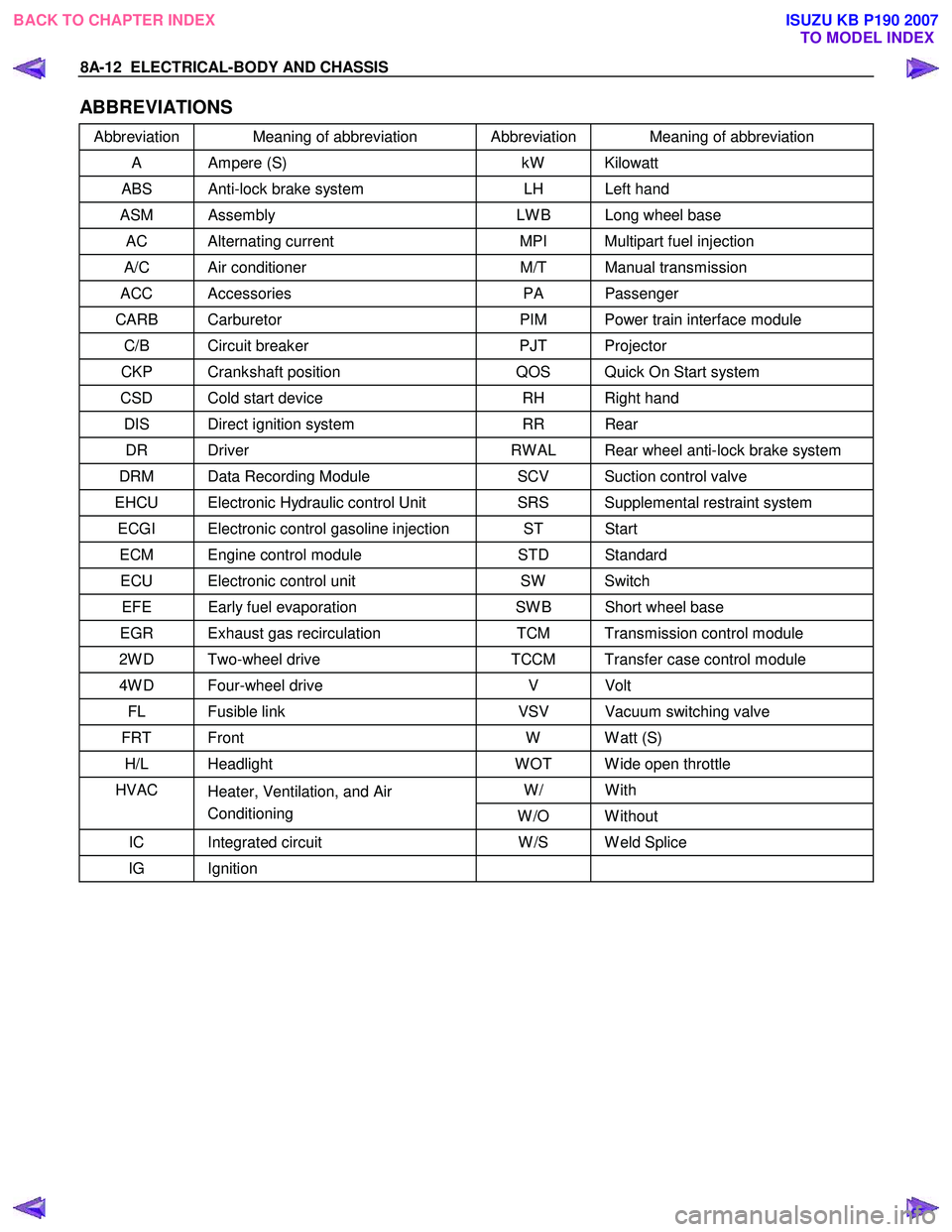
ABBREVIATIONS
Abbreviation Meaning of abbreviation Abbreviation Meaning of abbreviation
A Ampere (S) kW Kilowatt
ABS Anti-lock brake system LH Left hand
ASM Assembly LW B Long wheel base
AC Alternating current MPI Multipart fuel injection
A/C Air conditioner M/T Manual transmission
ACC Accessories PA Passenger
CARB Carburetor PIM Power train interface module
C/B Circuit breaker PJT Projector
CKP Crankshaft position QOS Quick On Start system
CSD Cold start device RH Right hand
DIS Direct ignition system RR Rear
DR Driver RW AL Rear wheel anti-lock brake system
DRM Data Recording Module SCV Suction control valve
EHCU Electronic Hydraulic control Unit SRS Supplemental restraint system
ECGI Electronic control gasoline injection ST Start
ECM Engine control module STD Standard
ECU Electronic control unit SW Switch
EFE Early fuel evaporation SW B Short wheel base
EGR Exhaust gas recirculation TCM Transmission control module
2W D Two-wheel drive TCCM Transfer case control module
4W D Four-wheel drive V Volt
FL Fusible link VSV Vacuum switching valve
FRT Front W W att (S)
H/L Headlight W OT W ide open throttle
W/ With HVAC
Heater, Ventilation, and Air
Conditioning W /O W ithout
IC Integrated circuit W /S W eld Splice
IG Ignition
BACK TO CHAPTER INDEX
TO MODEL INDEXISUZU KB P190 2007
Page 5292 of 6020
8A-354 ELECTRICAL-BODY AND CHASSIS
Installation
To Install, follow the removal steps in the reverse order.
FUEL GAUGE UNIT
Removal
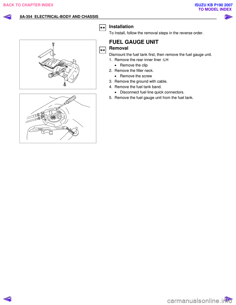
Dismount the fuel tank first, then remove the fuel gauge unit.
1. Remove the rear inner liner -LH
• Remove the clip
2. Remove the filler neck. • Remove the screw
3. Remove the ground with cable.
4. Remove the fuel tank band. • Disconnect fuel line quick connectors.
5. Remove the fuel gauge unit from the fuel tank.
BACK TO CHAPTER INDEX TO MODEL INDEXISUZU KB P190 2007
Page 5896 of 6020
IMMOBILIZER CONTROL SYSTEM (4JK1/4JJ1/HFV6) 11A-45
Description and Operation
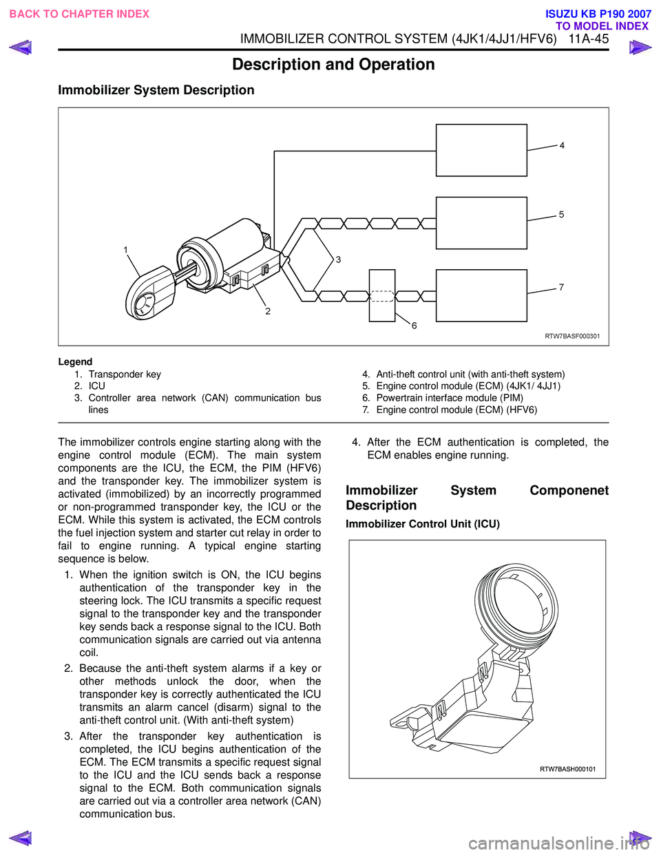
Immobilizer System Description
Legend1. Transponder key
2. ICU
3. Controller area network (CAN) communication bus lines 4. Anti-theft control unit (with anti-theft system)
5. Engine control module (ECM) (4JK1/ 4JJ1)
6. Powertrain interface module (PIM)
7. Engine control module (ECM) (HFV6)
The immobilizer controls engine starting along with the
engine control module (ECM). The main system
components are the ICU, the ECM, the PIM (HFV6)
and the transponder key. The immobilizer system is
activated (immobilized) by an incorrectly programmed
or non-programmed transponder key, the ICU or the
ECM. While this system is activated, the ECM controls
the fuel injection system and starter cut relay in order to
fail to engine running. A typical engine starting
sequence is below.
1. When the ignition switch is ON, the ICU begins authentication of the transponder key in the
steering lock. The ICU transmits a specific request
signal to the transponder key and the transponder
key sends back a response signal to the ICU. Both
communication signals are carried out via antenna
coil.
2. Because the anti-theft system alarms if a key or other methods unlock the door, when the
transponder key is correctly authenticated the ICU
transmits an alarm cancel (disarm) signal to the
anti-theft control unit. (With anti-theft system)
3. After the transponder key authentication is completed, the ICU begins authentication of the
ECM. The ECM transmits a specific request signal
to the ICU and the ICU sends back a response
signal to the ECM. Both communication signals
are carried out via a controller area network (CAN)
communication bus. 4. After the ECM authentication is completed, the
ECM enables engine running.
Immobilizer System Componenet
Description
Immobilizer Control Unit (ICU)
RTW7BASH000101
BACK TO CHAPTER INDEX TO MODEL INDEX
ISUZU KB P190 2007