2007 ISUZU KB P190 tow
[x] Cancel search: towPage 4121 of 6020
7A3-36 ON-VEHICLE SERVICE (AW30–40LE)
Installation
To install, follow the removal steps in reverse order
noting the following point;
1. Reinstall the parts removed with the valve bod
y
assembly to their assigned positions in the
transmission case (check valve assembly, C0
accumulator pistons, etc). Install the valve bod
y
assembly to the transmission case.
Refer to REASSEMBLY OF MAJOR
COMPONENTS (2).
2. Solenoid clamp bolt
Torque : 7 N ⋅
⋅⋅
⋅
m (0.7 kgf ⋅
⋅⋅
⋅
m/61 Ib ⋅
⋅⋅
⋅
in)
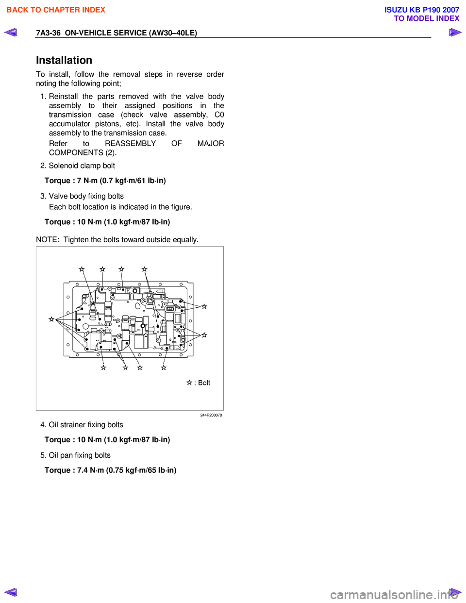
3. Valve body fixing bolts
Each bolt location is indicated in the figure.
Torque : 10 N ⋅
⋅⋅
⋅
m (1.0 kgf ⋅
⋅⋅
⋅
m/87 Ib ⋅
⋅⋅
⋅
in)
NOTE: Tighten the bolts toward outside equally.
244R200078
4. Oil strainer fixing bolts
Torque : 10 N ⋅
⋅⋅
⋅
m (1.0 kgf ⋅
⋅⋅
⋅
m/87 Ib ⋅
⋅⋅
⋅
in)
5. Oil pan fixing bolts
Torque : 7.4 N ⋅
⋅⋅
⋅
m (0.75 kgf ⋅
⋅⋅
⋅
m/65 Ib ⋅
⋅⋅
⋅
in)
BACK TO CHAPTER INDEX
TO MODEL INDEX
ISUZU KB P190 2007
Page 4166 of 6020
UNIT REPAIR (AW30–40LE) 7A4–31
If the values are nonstandard, check for an improper
installation.
248RY00004
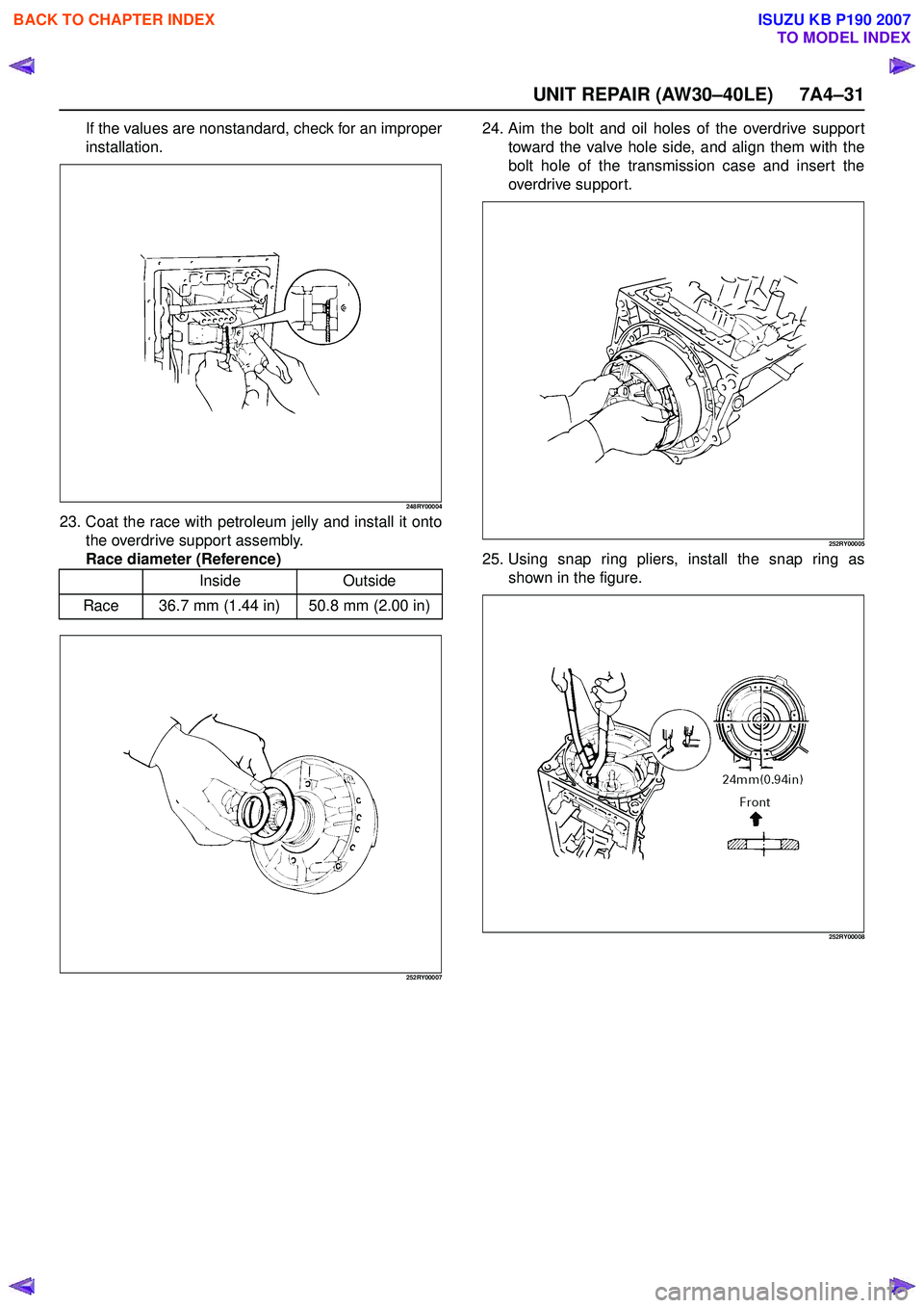
23. Coat the race with petroleum jelly and install it onto the overdrive support assembly.
Race diameter (Reference)
252RY00007
24. Aim the bolt and oil holes of the overdrive suppor t toward the valve hole side, and align them with the
bolt hole of the transmission case and insert the
overdrive support.
252RY00005
25. Using snap ring pliers, install the snap ring as shown in the figure.
252RY00008
Inside Outside
Race 36.7 mm (1.44 in) 50.8 mm (2.00 in)
BACK TO CHAPTER INDEX
TO MODEL INDEX
ISUZU KB P190 2007
Page 4378 of 6020
7A2-94 TRANSMISSION CONTROL SYSTEM (JR405E)
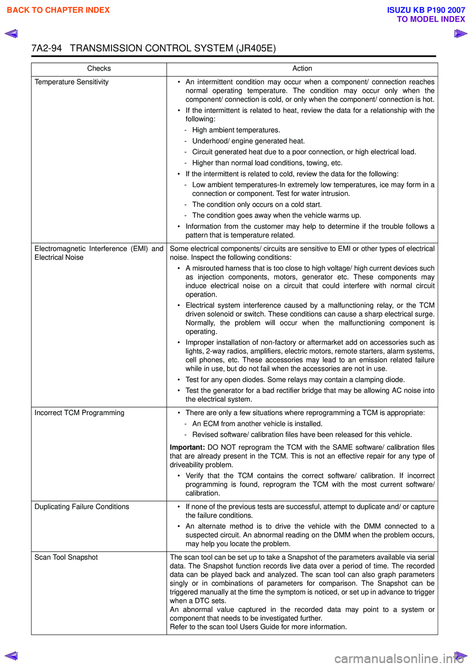
Temperature Sensitivity• An intermittent condition may occur when a component/ connection reaches
normal operating temperature. The condition may occur only when the
component/ connection is cold, or only when the component/ connection is hot.
• If the intermittent is related to heat, review the data for a relationship with the following:
- High ambient temperatures.
- Underhood/ engine generated heat.
- Circuit generated heat due to a poor connection, or high electrical load.
- Higher than normal load conditions, towing, etc.
• If the intermittent is related to cold, review the data for the following: - Low ambient temperatures-In extremely low temperatures, ice may form in a connection or component. Test for water intrusion.
- The condition only occurs on a cold start.
- The condition goes away when the vehicle warms up.
• Information from the customer may help to determine if the trouble follows a pattern that is temperature related.
Electromagnetic Interference (EMI) and
Electrical Noise Some electrical components/ circuits are sensitive to EMI or other types of electrical
noise. Inspect the following conditions:
• A misrouted harness that is too close to high voltage/ high current devices such as injection components, motors, generator etc. These components may
induce electrical noise on a circuit that could interfere with normal circuit
operation.
• Electrical system interference caused by a malfunctioning relay, or the TCM driven solenoid or switch. These conditions can cause a sharp electrical surge.
Normally, the problem will occur when the malfunctioning component is
operating.
• Improper installation of non-factory or aftermarket add on accessories such as lights, 2-way radios, amplifiers, electric motors, remote starters, alarm systems,
cell phones, etc. These accessories may lead to an emission related failure
while in use, but do not fail when the accessories are not in use.
• Test for any open diodes. Some relays may contain a clamping diode.
• Test the generator for a bad rectifier bridge that may be allowing AC noise into the electrical system.
Incorrect TCM Programming • There are only a few situations where reprogramming a TCM is appropriate:
- An ECM from another vehicle is installed.
- Revised software/ calibration files have been released for this vehicle.
Important: DO NOT reprogram the TCM with the SAME software/ calibration files
that are already present in the TCM. This is not an effective repair for any type of
driveability problem.
• Verify that the TCM contains the correct software/ calibration. If incorrect programming is found, reprogram the TCM with the most current software/
calibration.
Duplicating Failure Conditions • If none of the previous tests are successful, attempt to duplicate and/ or capture
the failure conditions.
• An alternate method is to drive the vehicle with the DMM connected to a suspected circuit. An abnormal reading on the DMM when the problem occurs,
may help you locate the problem.
Scan Tool Snapshot The scan tool can be set up to take a Snapshot of the parameters available via serial
data. The Snapshot function records live data over a period of time. The recorded
data can be played back and analyzed. The scan tool can also graph parameters
singly or in combinations of parameters for comparison. The Snapshot can be
triggered manually at the time the symptom is noticed, or set up in advance to trigger
when a DTC sets.
An abnormal value captured in the recorded data may point to a system or
component that needs to be investigated further.
Refer to the scan tool Users Guide for more information.
Checks
Action
BACK TO CHAPTER INDEX
TO MODEL INDEX
ISUZU KB P190 2007
Page 4456 of 6020
7A3-2 ON-VEHICLE SERVICE (JR405E)
DESCRIPTION
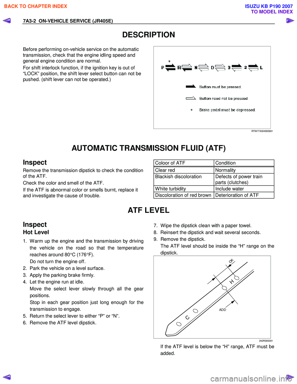
Before performing on-vehicle service on the automatic
transmission, check that the engine idling speed and
general engine condition are normal.
For shift interlock function, if the ignition key is out of
“LOCK” position, the shift lever select button can not be
pushed. (shift lever can not be operated.)
RTW 77ASH000901
AUTOMATIC TRANSMISSION FLUID (ATF)
Inspect
Remove the transmission dipstick to check the condition
of the ATF.
Check the color and smell of the ATF.
If the ATF is abnormal color or smells burnt, replace it
and investigate the cause of trouble.
Coloor of ATF Condition Clear red Normality
Blackish discoloration Defects of power train
parts (clutches)
W hite turbidity Include water
Discoloration of red brown Deterioration of ATF
ATF LEVEL
Inspect
Hot Level
1. W arm up the engine and the transmission by driving
the vehicle on the road so that the temperature
reaches around 80 °C (176 °F).
Do not turn the engine off.
2. Park the vehicle on a level surface.
3. Apply the parking brake firmly.
4. Let the engine run at idle.
Move the select lever slowly through all the gea
r
positions.
Stop in each gear position just long enough for the transmission to engage.
5. Return the select lever to either “P” or “N”.
6. Remove the ATF level dipstick.
7. W ipe the dipstick clean with a paper towel.
8. Reinsert the dipstick and wait several seconds.
9. Remove the dipstick.
The ATF level should be inside the “H” range on the dipstick.
242R300001
If the ATF level is below the “H” range, ATF must be added.
BACK TO CHAPTER INDEX
TO MODEL INDEX
ISUZU KB P190 2007
Page 4457 of 6020
ON-VEHICLE SERVICE (JR405E) 7A3-3
Cold Level
The vehicle must not have been driven so that the
temperature reaches around 20 °C (68 °F) before the
cold level check is made.
1. Park the vehicle on a level surface.
2. Apply the parking brake firmly.
3. Start the engine and allow it to warm up.
The engine coolant temperature gauge needle should be midway between the “C” mark and “H”
mark.
4. Let the engine run at idle.
Move the select lever slowly through all the gea
r
ranges.
Stop in each range just long enough for the transmission to engage.
5. Return the select lever either “P” or “N”.
6. Remove the ATF level dipstick.
7. W ipe the dipstick clean with a paper towel.
8. Reinsert the dipstick and wait several seconds.
9. Remove the dipstick.
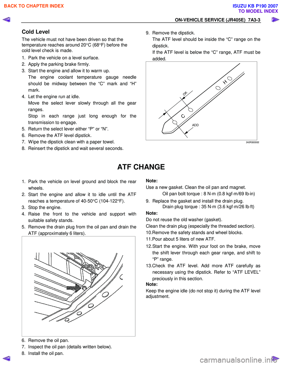
The ATF level should be inside the “C” range on the dipstick.
If the ATF level is below the “C” range, ATF must be added.
242R300002
ATF CHANGE
1. Park the vehicle on level ground and block the rear
wheels.
2. Start the engine and allow it to idle until the ATF reaches a temperature of 40-50 °C (104-122 °F).
3. Stop the engine.
4. Raise the front to the vehicle and support with suitable safety stands.
5. Remove the drain plug from the oil pan and drain the ATF (approximately 6 liters).
6. Remove the oil pan.
7. Inspect the oil pan (details written below).
8. Install the oil pan.
Note:
Use a new gasket. Clean the oil pan and magnet.
Oil pan bolt torque : 8 N ⋅m (0.8 kgf ⋅m/69 lb ⋅in)
9. Replace the gasket and install the drain plug.
Drain plug torque : 35 N ⋅m (3.6 kgf ⋅m/26 lb ⋅ft)
Note:
Do not reuse the old washer (gasket).
Clean the drain plug (especially the threaded section).
10.Remove the safety stands and wheel blocks.
11.Pour about 5 liters of new ATF.
12. Start the engine. W ith your foot on the brake, move the shift lever through each gear range, and shift to
“P” range.
13.Check the ATF level. Add more ATF carefully as necessary using the dipstick. Refer to “ATF LEVEL”
preciously in this section.
Note:
Keep the engine idle (do not stop it) during the ATF level
adjustment.
BACK TO CHAPTER INDEX
TO MODEL INDEX
ISUZU KB P190 2007
Page 4468 of 6020
7A3-14 ON-VEHICLE SERVICE (JR405E)
Install or Connect
1. Install the shift cable toward the inside of the cabin
from the bottom of the vehicle.
2. Push the shift cable into the select lever base.
3. Connect the shift cable to the select lever.
4. Fix the shift cable to the bracket.
Install the clip on the marking on the shift cable.
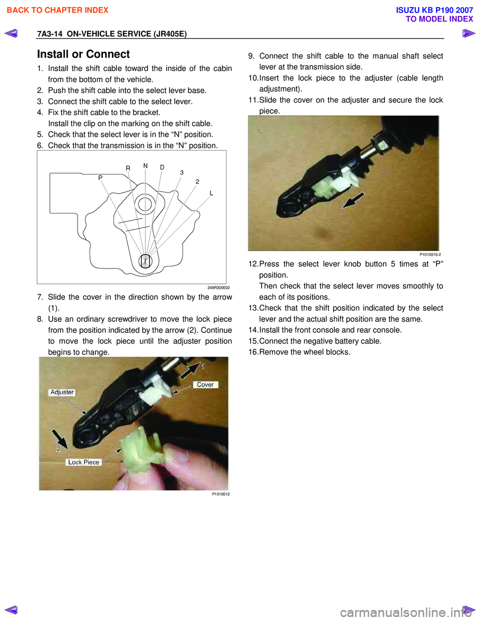
5. Check that the select lever is in the “N” position.
6. Check that the transmission is in the “N” position.
249R300002
7. Slide the cover in the direction shown by the arrow
(1).
8. Use an ordinary screwdriver to move the lock piece from the position indicated by the arrow (2). Continue
to move the lock piece until the adjuster position
begins to change.
P1010012
9. Connect the shift cable to the manual shaft select
lever at the transmission side.
10. Insert the lock piece to the adjuster (cable length adjustment).
11. Slide the cover on the adjuster and secure the lock piece.
P1010016-2
12. Press the select lever knob button 5 times at “P”position.
Then check that the select lever moves smoothly to each of its positions.
13. Check that the shift position indicated by the select lever and the actual shift position are the same.
14. Install the front console and rear console.
15. Connect the negative battery cable.
16. Remove the wheel blocks.
BACK TO CHAPTER INDEX
TO MODEL INDEX
ISUZU KB P190 2007
Page 4572 of 6020
7B-8 MSG MODEL
Exhaust Pipe
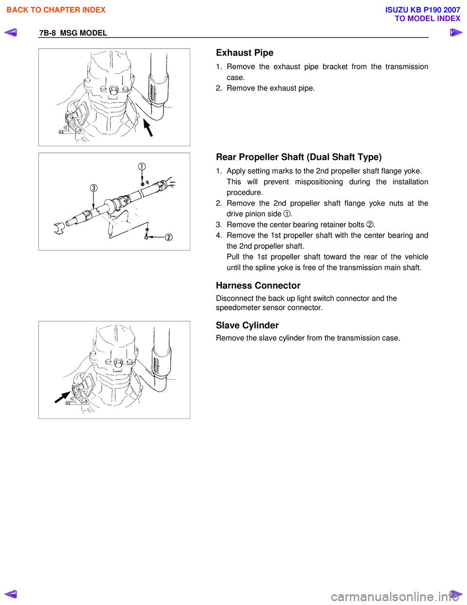
1. Remove the exhaust pipe bracket from the transmission
case.
2. Remove the exhaust pipe.
Rear Propeller Shaft (Dual Shaft Type)
1. Apply setting marks to the 2nd propeller shaft flange yoke.
This will prevent mispositioning during the installation procedure.
2. Remove the 2nd propeller shaft flange yoke nuts at the drive pinion side
1.
3. Remove the center bearing retainer bolts
2 .
4. Remove the 1st propeller shaft with the center bearing and the 2nd propeller shaft.
Pull the 1st propeller shaft toward the rear of the vehicle until the spline yoke is free of the transmission main shaft.
Harness Connector
Disconnect the back up light switch connector and the
speedometer sensor connector.
Slave Cylinder
Remove the slave cylinder from the transmission case.
BACK TO CHAPTER INDEX
TO MODEL INDEX
ISUZU KB P190 2007
Page 4574 of 6020
7B-10 MSG MODEL
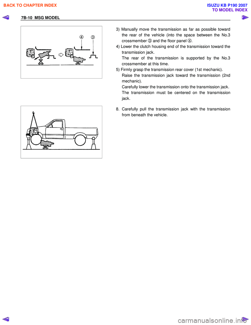
3) Manually move the transmission as far as possible toward
the rear of the vehicle (into the space between the No.3
crossmember
3 and the floor panel 4 .
4) Lower the clutch housing end of the transmission toward the transmission jack.
The rear of the transmission is supported by the No.3 crossmember at this time.
5) Firmly grasp the transmission rear cover (1st mechanic).
Raise the transmission jack toward the transmission (2nd mechanic).
Carefully lower the transmission onto the transmission jack.
The transmission must be centered on the transmission jack.
8. Carefully pull the transmission jack with the transmission
from beneath the vehicle.
BACK TO CHAPTER INDEX
TO MODEL INDEX
ISUZU KB P190 2007