2007 ISUZU KB P190 tow
[x] Cancel search: towPage 5174 of 6020
8A-236 ELECTRICAL-BODY AND CHASSIS
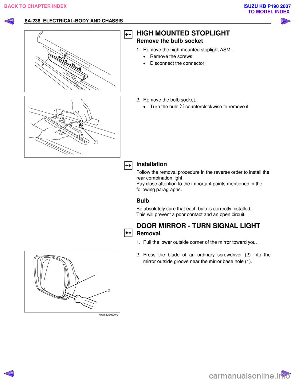
HIGH MOUNTED STOPLIGHT
Remove the bulb socket
1. Remove the high mounted stoplight ASM. • Remove the screws.
• Disconnect the connector.
2. Remove the bulb socket.
• Turn the bulb
1 counterclockwise to remove it.
Installation
Follow the removal procedure in the reverse order to install the
rear combination light.
Pay close attention to the important points mentioned in the
following paragraphs.
Bulb
Be absolutely sure that each bulb is correctly installed.
This will prevent a poor contact and an open circuit.
DOOR MIRROR - TURN SIGNAL LIGHT
Removal
1. Pull the lower outside corner of the mirror toward you.
RUW 580SH000701
2. Press the blade of an ordinary screwdriver (2) into the
mirror outside groove near the mirror base hole (1).
BACK TO CHAPTER INDEX TO MODEL INDEXISUZU KB P190 2007
Page 5175 of 6020
ELECTRICAL-BODY AND CHASSIS 8A-237
RUW 580SH000801
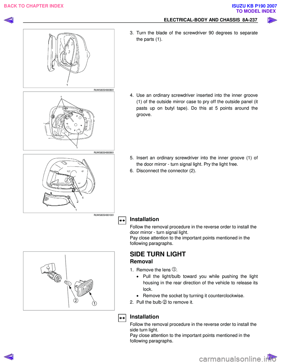
3. Turn the blade of the screwdriver 90 degrees to separate
the parts (1).
RUW 580SH000901
4. Use an ordinary screwdriver inserted into the inner groove
(1) of the outside mirror case to pry off the outside panel (it
pasts up on butyl tape). Do this at 5 points around the
groove.
RUW 580SH001001
5. Insert an ordinary screwdriver into the inner groove (1) of
the door mirror - turn signal light. Pry the light free.
6. Disconnect the connector (2).
Installation
Follow the removal procedure in the reverse order to install the
door mirror - turn signal light.
Pay close attention to the important points mentioned in the
following paragraphs.
SIDE TURN LIGHT
Removal
1. Remove the lens 1.
• Pull the light/bulb toward you while pushing the light
housing in the rear direction of the vehicle to release its
lock.
• Remove the socket by turning it counterclockwise.
2. Pull the bulb
2 to remove it.
Installation
Follow the removal procedure in the reverse order to install the
side turn light.
Pay close attention to the important points mentioned in the
following paragraphs.
BACK TO CHAPTER INDEX TO MODEL INDEXISUZU KB P190 2007
Page 5427 of 6020
ELECTRICAL-BODY AND CHASSIS 8A-489
INSPECTION AND REPAIR
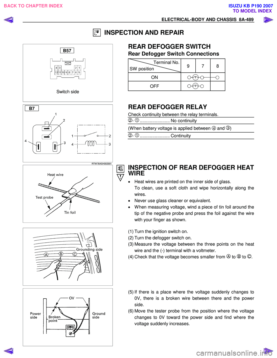
Switch side
B57
REAR DEFOGGER SWITCH
Rear Defogger Switch Connections
Terminal No.
SW position 9 7 8
ON
OFF
B7
RTW 78ASH002901
REAR DEFOGGER RELAY
Check continuity between the relay terminals.
2- 1........................ No continuity
(W hen battery voltage is applied between 4 and 3)
2- 1........................ Continuity
INSPECTION OF REAR DEFOGGER HEAT
WIRE
• Heat wires are printed on the inner side of glass.
To clean, use a soft cloth and wipe horizontally along the wires.
• Never use glass cleaner or equivalent.
• W hen measuring voltage, wind a piece of tin foil around the
tip of the negative probe and press the foil against the wire
with your finger as shown.
(1) Turn the ignition switch on.
(2) Turn the defogger switch on.
(3) Measure the voltage between the three points on the heat wire and the (-) terminal with a voltmeter.
(4) Check that the voltage becomes smaller from
A to B to C.
(5) If there is a place where the voltage suddenly changes to
0V, there is a broken wire between there and the powe
r
side.
(6) Move the tester probe from the position where the voltage changes to 0V toward the power side and find where the
voltage suddenly increases.
BACK TO CHAPTER INDEX TO MODEL INDEXISUZU KB P190 2007
Page 5649 of 6020
9A-14 SUPPLEMENTAL RESTRAINT SYSTEM
Component Description
SRS Control Unit
WARNING: DURING SERVICE PROCEDURES, BE
VERY CAREFUL WHEN HANDLING A SRS
CONTROL UNIT. NEVER STRIKE OR JAR THE SRS
CONTORL UNIT. NEVER POWER UP THE SRS
WHEN THE SRS CONTROL UNIT IS NOT RIGIDLY
ATTACHED TO THE VEHICLE. ALL SRS CONTROL
UNIT AND MOUNTING BRACKET FASTENERS
MUST BE CAREFULLY TORQUED AND THE
ARROW MUST BE POINTED TOWARD THE FRONT
OF THE VEHICLE TO ENSURE PROPER
OPERATION OF THE SRS. THE SRS CONTROL
UNIT COULD BE ACTIVATED WHEN POWERED
WHILE NOT RIGIDLY ATTACHED TO THE
VEHICLE WHICH COULD CAUSE DEPLOYMENT
AND RESULT IN PERSONAL INJURY.
The SRS control unit is designed to perform the
following functions in the SRS:
1. Energy Reserve — The SRS control unit maintains 30–Volt Loop Reserve (30VLR) energy supply to
provide deployment energy when ignition voltage is
lost in a frontal crash.
2. Frontal Crash Detection — The SRS control unit monitors vehicle velocity changes to detect frontal
crashes which are severe enough to warrant
deployment.
3. Air Bag Deployment — W hen a frontal crash o
f
sufficient force is detected, the SRS control unit
will cause enough current to flow through the ai
r
bag assembly to deploy the air bag.
4. Malfunction Detection — The SRS control unit performs diagnostic monitoring of SRS electrical
components and sets a diagnostic trouble code
when a malfunction is detected.
5. Frontal Crash Recording — The SRS control unit records information regarding SRS status during
frontal crash.
6. Malfunction Diagnosis — The SRS control unit displays SRS diagnostic trouble codes and system
status information through the use of a scan tool.
7. Driver Notification — The SRS control unit warns the vehicle driver of SRS malfunctions b
y
controlling the “SRS” warning lamp.
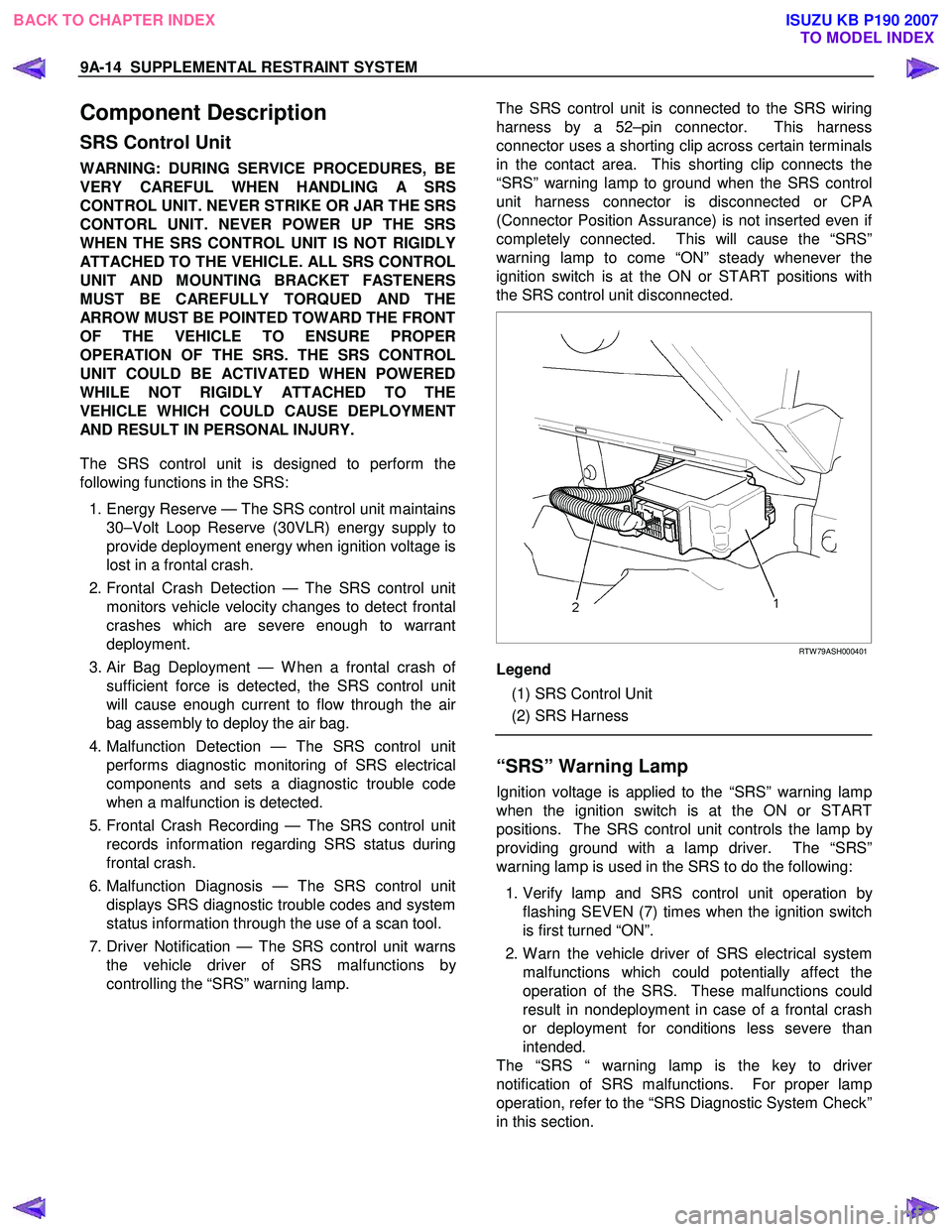
The SRS control unit is connected to the SRS wiring
harness by a 52–pin connector. This harness
connector uses a shorting clip across certain terminals
in the contact area. This shorting clip connects the
“SRS” warning lamp to ground when the SRS control
unit harness connector is disconnected or CP
A
(Connector Position Assurance) is not inserted even i
f
completely connected. This will cause the “SRS”
warning lamp to come “ON” steady whenever the
ignition switch is at the ON or START positions with
the SRS control unit disconnected.
RTW 79ASH000401
Legend
(1) SRS Control Unit
(2) SRS Harness
“SRS” Warning Lamp
Ignition voltage is applied to the “SRS” warning lamp
when the ignition switch is at the ON or START
positions. The SRS control unit controls the lamp b
y
providing ground with a lamp driver. The “SRS”
warning lamp is used in the SRS to do the following:
1. Verify lamp and SRS control unit operation b
y
flashing SEVEN (7) times when the ignition switch
is first turned “ON”.
2. W arn the vehicle driver of SRS electrical system malfunctions which could potentially affect the
operation of the SRS. These malfunctions could
result in nondeployment in case of a frontal crash
or deployment for conditions less severe than
intended.
The “SRS “ warning lamp is the key to drive
r
notification of SRS malfunctions. For proper lamp
operation, refer to the “SRS Diagnostic System Check”
in this section.
BACK TO CHAPTER INDEX TO MODEL INDEXISUZU KB P190 2007
Page 5656 of 6020
SUPPLEMENTAL RESTRAINT SYSTEM 9A-21
On–Vehicle Service
Service Precaution
WARNING: WHEN PERFORMING SERVICE ON OR
AROUND SRS COMPONENTS OR SRS WIRING,
FOLLOW THE PROCEDURES LISTED BELOW TO
TEMPORARILY DISABLE THE SRS. FAILURE TO
FOLLOW PROCEDURES COULD RESULT IN
POSSIBLE AIR BAG DEPLOYMENT, PERSONAL
INJURY OR OTHERWISE UNNECESSARY SRS
REPAIRS.
The SRS control unit in Driver–Passenger SRS can
maintain sufficient voltage to cause a deployment fo
r
up to 15 seconds after the ignition switch is turned
“OFF,” the battery is disconnected, or the fuse
powering the SRS control unit is removed.
Many of the service procedures require removal of the
“SRS” fuse, and disconnection of the air bag assembl
y
from the deployment loop to avoid an accidental
deployment. If the air bag assembly is disconnected
from the deployment loop as noted in the “Disabling
the SRS” procedure that follows, service can begin
immediately without waiting for the 15 second time
period to expire.
Disabling The SRS
Removal
Turn the ignition switch to “LOCK” and remove the
key.
1. Remove the SRS fuse “SRS”, from the side of the driver’s side of the instrument panel fuse block o
r
disconnect the battery.
2. Disconnect the yellow connector at the base of the steering column.
3. Remove the glove box assembly, refer to “Passenger Air Bag Assembly Replacement” in
this manual.
4. Disconnect the yellow connector behind the glove box assembly.
CAUTION: With the “SRS” fuse removed and
ignition switched “ON”, the “SRS” warning lamp
will be “ON”. This is normal operation and does
not indicate an SRS malfunction.
Enabling The SRS
Installation
CAUTION: Never use the air bag assembly from
another vehicle or different model year air bag
assembly.
Use only a new air bag assembly matched to the
TFR/S which is being repaired.
Turn the ignition switch to “LOCK” and remove the
key.
1. Connect the yellow connector passenger air bag assembly.
2. Install the glove box assembly. Refer to “Passenger air bag assembly replacement” in this
manual.
3. Connect the yellow connector at the base of the steering column.
4. Install the “AIR BAG” fuse “SRS” to the side of the driver’s side of the instrument panel fuse block o
r
connect the battery.
Turn the ignition switch to “ON” and verify that the
“SRS” warning lamp flashes seven times and then
turns to “LOCK”. If it does not operate as described,
perform the “SRS Diagnostic System Check” in this
manual.
Handling / Installation / Diagnosis
1. The air bag assembly should not be subjected to temperatures above 65
°C (150°F).
2. The air bag assembly, and SRS control unit, should not be used if they have been dropped from
a height of 100 centimeters (3.28 feet) or more.
3. W hen the SRS control unit is replaced, it must be oriented with the arrow on the sensor pointing
toward the front of the vehicle. It is very important
for the SRS control unit to be located flat on the
mounting surface, parallel to the vehicle datum
line. It is important that the SRS control unit
mounting surface is free of any dirt or other foreign
material.
4. Do not apply power to the SRS unless all components are connected or a diagnostic chart
requests it, as this will set a diagnostic trouble
code.
5. The “SRS Diagnostic System Check” must be the starting point of any SRS diagnostics. The “SRS
Diagnostic System Check” will verify proper “SRS”
warning lamp operation and will lead you to the
correct chart to diagnose any SRS malfunctions.
Bypassing these procedures may result in
extended diagnostic time, incorrect diagnosis, and
incorrect parts replacement.
BACK TO CHAPTER INDEX TO MODEL INDEXISUZU KB P190 2007
Page 5667 of 6020
9A-32 SUPPLEMENTAL RESTRAINT SYSTEM
Service Precautions for SRS
Component Service
CAUTION: When fasteners are removed, always
reinstall them at the same location from which
they were removed. If a fastener needs to be
replaced, use the correct part number fastener fo
r
that application. If the correct part number
fastener is not available, a fastener of equal size
and strength (or stronger) may be used. Fasteners
that are not reused, and those requiring a thread
locking compound will be called out. The correct
torque value must be used when installing
fasteners that require it. If the above conditions
are not followed, parts or system damage could
result.
WARNING: WHEN PERFORMING SERVICE ON OR
AROUND SRS COMPONENTS OR SRS WIRING,
FOLLOW THE PROCEDURES LISTED BELOW TO
TEMPORARILY DISABLE THE SRS. FAILURE TO
FOLLOW PROCEDURES COULD RESULT IN
POSSIBLE AIR BAG DEPLOYMENT, PERSONAL
INJURY OR OTHERWISE UNNEEDED SRS
REPAIRS.
The SRS control unit in the Driver–Passenger SRS
can maintain sufficient voltage to cause a deployment
for up to 15 seconds after the ignition switch is turned
“OFF,” the battery is disconnected, or the fuse
powering the SRS control unit is removed.
Many of the service procedures require removal of the
“SRS” fuse, and disconnection of the air bag assembl
y
from the deployment loop to avoid an accidental
deployment. If the air bag assembly is disconnected
from the deployment loop as noted in the “Disabling
the SRS” procedure that follows, service can begin
immediately without waiting for the 15 second time
period to expire.
Disabling The SRS
Removal
Turn the ignition switch to “OFF” and turn the steering
wheel so that the vehicle's wheels are pointing straight
ahead.
1. Remove the SRS fuse “SRS” from the left dash side lower fuse block or disconnect the battery.
2. Disconnect the yellow connector at the base o
f
steering column.
3. Remove the glove box assembly; Refer to “Passenger air bag assembly replacement” in this
section.
4. Disconnect the passenger air bag assembly yello
w
connector behind the glove box assembly.
CAUTION: With the “SRS” fuse removed and the
ignition switch to “ON,” the “SRS” warning lamp
will be “ON.” This is normal operation and does
not indicate an SRS malfunction.
Enabling The SRS
Installation
Turn the ignition switch to “LOCK” and remove the
key.
1. Connect the yellow connector passenger air bag assembly.
2. Install the glove box assembly. Refer to “Passenger Air Bag Assembly Replacement” in
this section.
3. Connect the yellow connector at the base of the steering column.
4. Install the “AIR BAG” fuse “SRS” to the left dash side lower fuse block or connect the battery.
Turn the ignition switch to “ON” and verify that the
“SRS” warning lamp flashes seven times and then
turns to “LOCK”. If it does not operate as described,
perform the “SRS Diagnostic System Check” in this
section.
Handling / Installation / Diagnosis
1. Air bag assembly should not be subjected to
temperatures above 65 °C (150 °F).
2.
Air bag assembly, and SRS control unit should not
be used if they have been dropped from a height
of 100 centimeters (3.28 feet) or more.
3. W hen a SRS control unit is replaced, it must be oriented with the arrow on the SRS control unit
pointing toward the front of the vehicle. It is ver
y
important for the SRS control unit to be located flat
on the mounting surface, parallel to the vehicle
datum line. It is important that the SRS control unit
mounting surface is free of any dirt or other foreign
material.
4. Do not apply power to the SRS unless all components are connected or a diagnostic chart
requests it, as this will set a diagnostic trouble
code.
5. The “SRS Diagnostic System Check” must be the starting point of any SRS diagnostics. The “SRS
Diagnostic System Check” will verify proper “SRS”
warning lamp operation and will lead you to the
correct chart to diagnose any SRS malfunctions.
Bypassing these procedures may result in
extended diagnostic time, incorrect diagnosis, and
incorrect parts replacements.
BACK TO CHAPTER INDEX TO MODEL INDEXISUZU KB P190 2007
Page 5670 of 6020
SUPPLEMENTAL RESTRAINT SYSTEM 9A-35
SRS Control Unit
Service Precautions
WARNING: DURING SERVICE PROCEDURES, BE
VERY CAREFUL WHEN HANDLING THE SRS
CONTROL UNIT. NEVER STRIKE OR JAR THE SRS
CONTROL UNIT. UNDER SOME
CIRCUMSTANCES, IT COULD CAUSE
DEPLOYMENT AND RESULT IN PERSONAL
INJURY OR IMPROPER OPERATION OF THE
SUPPLEMENTAL RESTRAINT SYSTEM (SRS).
THE SRS CONTROL UNIT MOUNTING BRACKET
BOLTS MUST BE CAREFULLY TORQUED TO
ASSURE PROPER OPERATION. NEVER POWER
UP THE SRS WHEN THE SRS CONTROL UNIT IS
NOT RIGIDLY ATTACHED TO THE VEHICLE. THE
SRS CONTROL UNIT COULD BE ACTIVATED
WHEN POWERED WHILE NOT RIGIDLY
ATTACHED TO THE VEHICLE WHICH COULD
CAUSE DEPLOYMENT AND RESULT IN
PERSONAL INJURY.
WARNING: PROPER OPERATION OF THE SRS
CONTROL UNIT REQUIRES THE SRS CONTROL
UNIT TO BE RIGIDLY ATTACHED TO THE
VEHICLE STRUCTURE AND THAT THE ARROW
ON THE SENSOR BE POINTING TOWARD THE
FRONT OF THE VEHICLE.
The SRS control unit is specifically calibrated and is
keyed to the SRS control unit location SRS wiring
harness. Caution should be used to ensure prope
r
location of the SRS control unit. The keying of the
SRS control unit to its location and wiring harness
connectors should never be modified in the field.
Removal
1. Disable the SRS (Refer to “Disabling the SRS” in this section).
2. Remove the transmission knob (for M/T) and transfer lever knob.
3. Remove the front console assembly and disconnect the wiring harness connector.
4. Disconnect the SRS control unit harness connector.
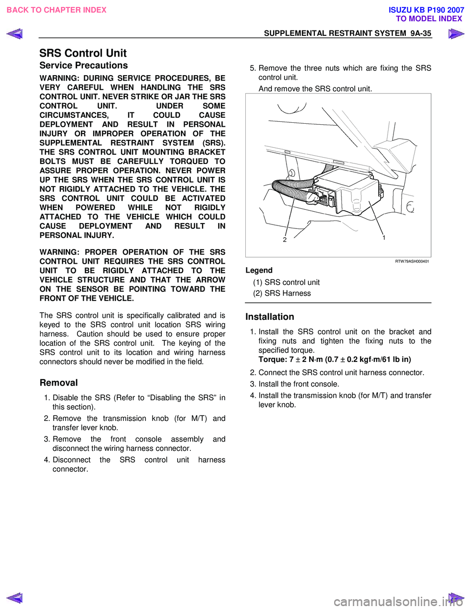
5. Remove the three nuts which are fixing the SRS
control unit.
And remove the SRS control unit.
RTW 79ASH000401
Legend
(1) SRS control unit
(2) SRS Harness
Installation
1. Install the SRS control unit on the bracket and
fixing nuts and tighten the fixing nuts to the
specified torque.
Torque: 7 ±
±±
±
2 N ⋅
⋅⋅
⋅
m (0.7 ±
±±
±
0.2 kgf ⋅
⋅⋅
⋅
m/61 lb in)
2. Connect the SRS control unit harness connector.
3. Install the front console.
4. Install the transmission knob (for M/T) and transfe
r
lever knob.
BACK TO CHAPTER INDEX TO MODEL INDEXISUZU KB P190 2007
Page 5693 of 6020
RESTRAINT CONTROL SYSTEM 9A1-11
3. W hen all circuitry outside the SRS control unit has been found to operate properly, as indicated by the
appropriate diagnostic chart, then and only then
should the SRS control unit be replaced.
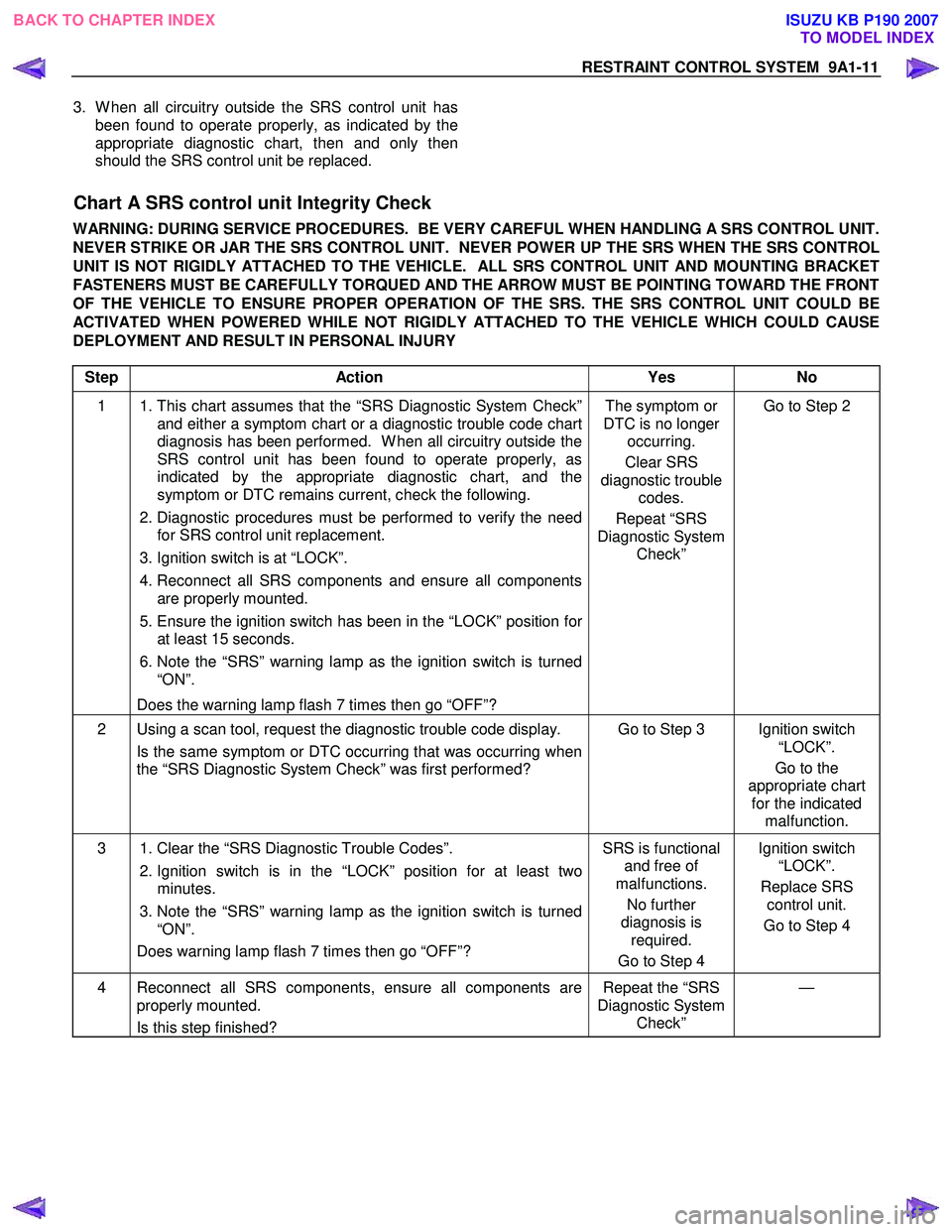
Chart A SRS control unit Integrity Check
WARNING: DURING SERVICE PROCEDURES. BE VERY CAREFUL WHEN HANDLING A SRS CONTROL UNIT.
NEVER STRIKE OR JAR THE SRS CONTROL UNIT. NEVER POWER UP THE SRS WHEN THE SRS CONTROL
UNIT IS NOT RIGIDLY ATTACHED TO THE VEHICLE. ALL SRS CONTROL UNIT AND MOUNTING BRACKET
FASTENERS MUST BE CAREFULLY TORQUED AND THE ARROW MUST BE POINTING TOWARD THE FRONT
OF THE VEHICLE TO ENSURE PROPER OPERATION OF THE SRS. THE SRS CONTROL UNIT COULD BE
ACTIVATED WHEN POWERED WHILE NOT RIGIDLY ATTACHED TO THE VEHICLE WHICH COULD CAUSE
DEPLOYMENT AND RESULT IN PERSONAL INJURY
Step Action Yes No
1 1. This chart assumes that the “SRS Diagnostic System Check”
and either a symptom chart or a diagnostic trouble code chart
diagnosis has been performed. W hen all circuitry outside the
SRS control unit has been found to operate properly, as
indicated by the appropriate diagnostic chart, and the
symptom or DTC remains current, check the following.
2. Diagnostic procedures must be performed to verify the need
for SRS control unit replacement.
3. Ignition switch is at “LOCK”.
4. Reconnect all SRS components and ensure all components are properly mounted.
5. Ensure the ignition switch has been in the “LOCK” position for
at least 15 seconds.
6. Note the “SRS” warning lamp as the ignition switch is turned
“ON”.
Does the warning lamp flash 7 times then go “OFF”? The symptom or
DTC is no longer occurring.
Clear SRS
diagnostic trouble codes.
Repeat “SRS
Diagnostic System Check” Go to Step 2
2 Using a scan tool, request the diagnostic trouble code display.
Is the same symptom or DTC occurring that was occurring when
the “SRS Diagnostic System Check” was first performed? Go to Step 3 Ignition switch
“LOCK”.
Go to the
appropriate chart for the indicated malfunction.
3 1. Clear the “SRS Diagnostic Trouble Codes”.
2. Ignition switch is in the “LOCK” position for at least two
minutes.
3. Note the “SRS” warning lamp as the ignition switch is turned
“ON”.
Does warning lamp flash 7 times then go “OFF”? SRS is functional
and free of
malfunctions.
No further
diagnosis is required.
Go to Step 4 Ignition switch
“LOCK”.
Replace SRS control unit.
Go to Step 4
4 Reconnect all SRS components, ensure all components are properly mounted.
Is this step finished? Repeat the “SRS
Diagnostic System Check” —
BACK TO CHAPTER INDEX
TO MODEL INDEX
ISUZU KB P190 2007