Page 4586 of 6020
7B-22 MSG MODEL
27. Bearing Snap Ring
28. Intermediate Plate
1) Insert the snap ring pliers into the mainshaft bearing snap ring hole.
The snap ring hole is in the intermediate plate
2.
2) Use the snap ring pliers
1to force open the mainshaft
bearing snap ring
3.
Hold the snap ring open with the pliers.
3) Push the intermediate plate toward the rear of the transmission to remove it.
The ball bearing snap ring will come free.
BACK TO CHAPTER INDEX
TO MODEL INDEX
ISUZU KB P190 2007
Page 4634 of 6020
7B1-28 MANUAL TRANSMISSION
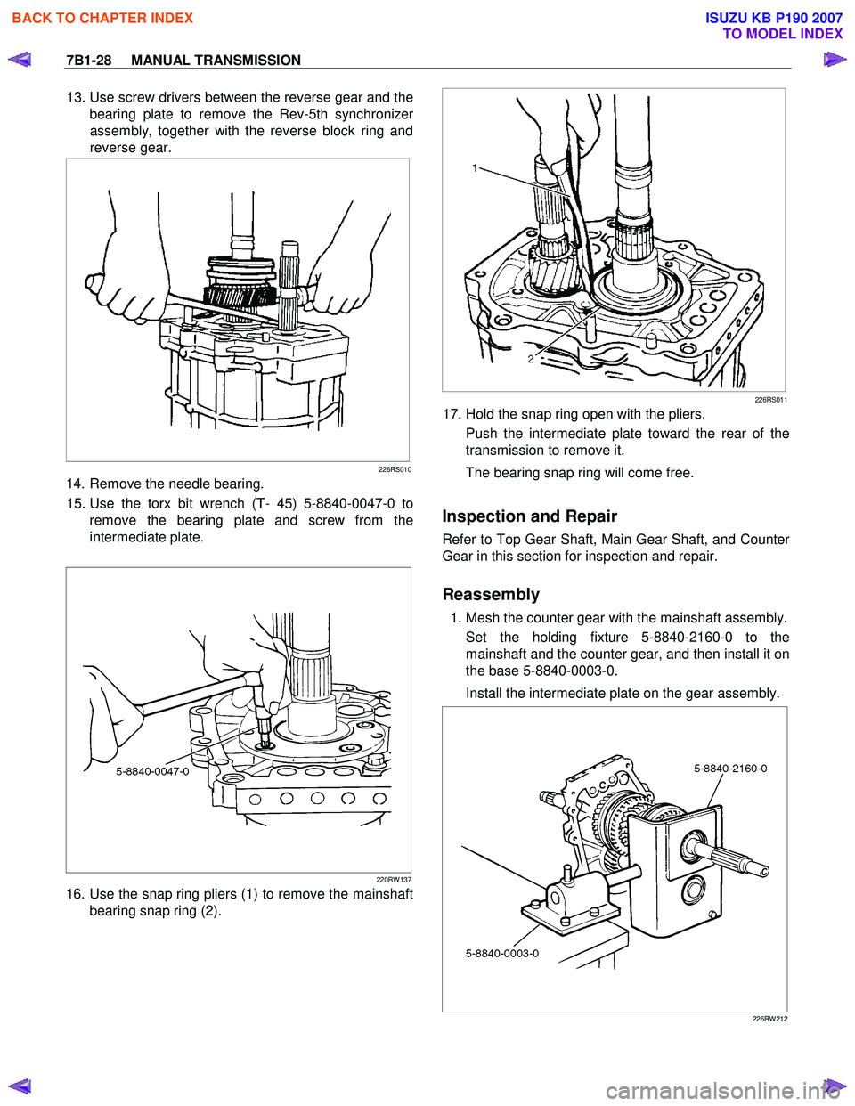
13. Use screw drivers between the reverse gear and the
bearing plate to remove the Rev-5th synchronize
r
assembly, together with the reverse block ring and
reverse gear.
226RS010
14. Remove the needle bearing.
15. Use the torx bit wrench (T- 45) 5-8840-0047-0 to remove the bearing plate and screw from the
intermediate plate.
220RW 137
16. Use the snap ring pliers (1) to remove the mainshaft bearing snap ring (2).
226RS011
17. Hold the snap ring open with the pliers.
Push the intermediate plate toward the rear of the
transmission to remove it.
The bearing snap ring will come free.
Inspection and Repair
Refer to Top Gear Shaft, Main Gear Shaft, and Counter
Gear in this section for inspection and repair.
Reassembly
1. Mesh the counter gear with the mainshaft assembly. Set the holding fixture 5-8840-2160-0 to the
mainshaft and the counter gear, and then install it on
the base 5-8840-0003-0.
Install the intermediate plate on the gear assembly.
226RW 212
BACK TO CHAPTER INDEX
TO MODEL INDEX
ISUZU KB P190 2007
Page 4635 of 6020
MANUAL TRANSMISSION 7B1-29
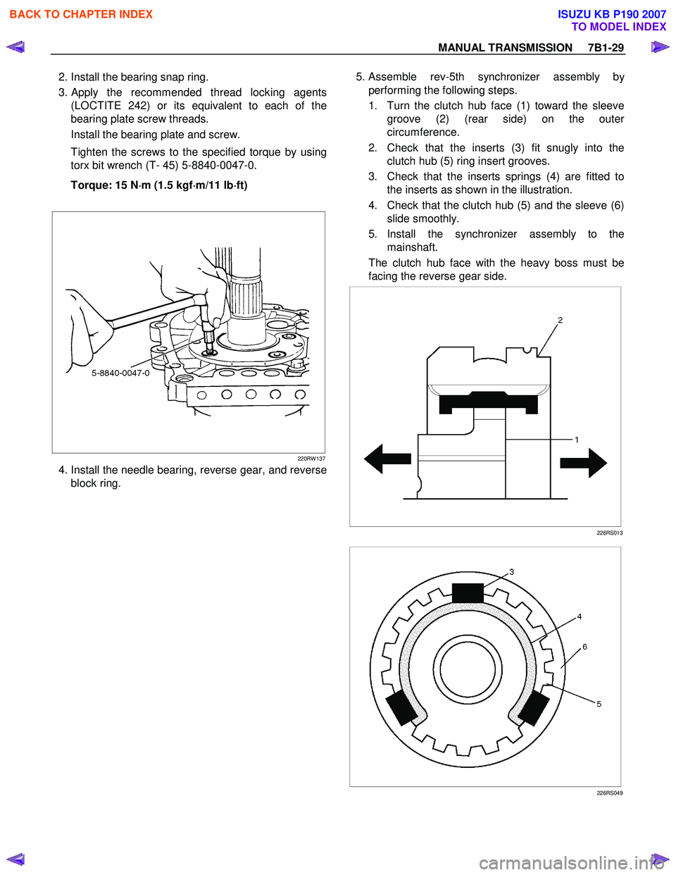
2. Install the bearing snap ring.
3.
Apply the recommended thread locking agents
(LOCTITE 242) or its equivalent to each of the
bearing plate screw threads.
Install the bearing plate and screw.
Tighten the screws to the specified torque by using
torx bit wrench (T- 45) 5-8840-0047-0.
Torque: 15 N ⋅
⋅⋅
⋅
m (1.5 kgf ⋅
⋅⋅
⋅
m/11 lb ⋅
⋅⋅
⋅
ft)
220RW 137
4. Install the needle bearing, reverse gear, and reverse block ring. 5. Assemble rev-5th synchronizer assembly b
y
performing the following steps.
1. Turn the clutch hub face (1) toward the sleeve groove (2) (rear side) on the oute
r
circumference.
2. Check that the inserts (3) fit snugly into the clutch hub (5) ring insert grooves.
3. Check that the inserts springs (4) are fitted to the inserts as shown in the illustration.
4. Check that the clutch hub (5) and the sleeve (6) slide smoothly.
5. Install the synchronizer assembly to the mainshaft.
The clutch hub face with the heavy boss must be
facing the reverse gear side.
226RS013
226RS049
BACK TO CHAPTER INDEX
TO MODEL INDEX
ISUZU KB P190 2007
Page 4688 of 6020
7B1-82 MANUAL TRANSMISSION
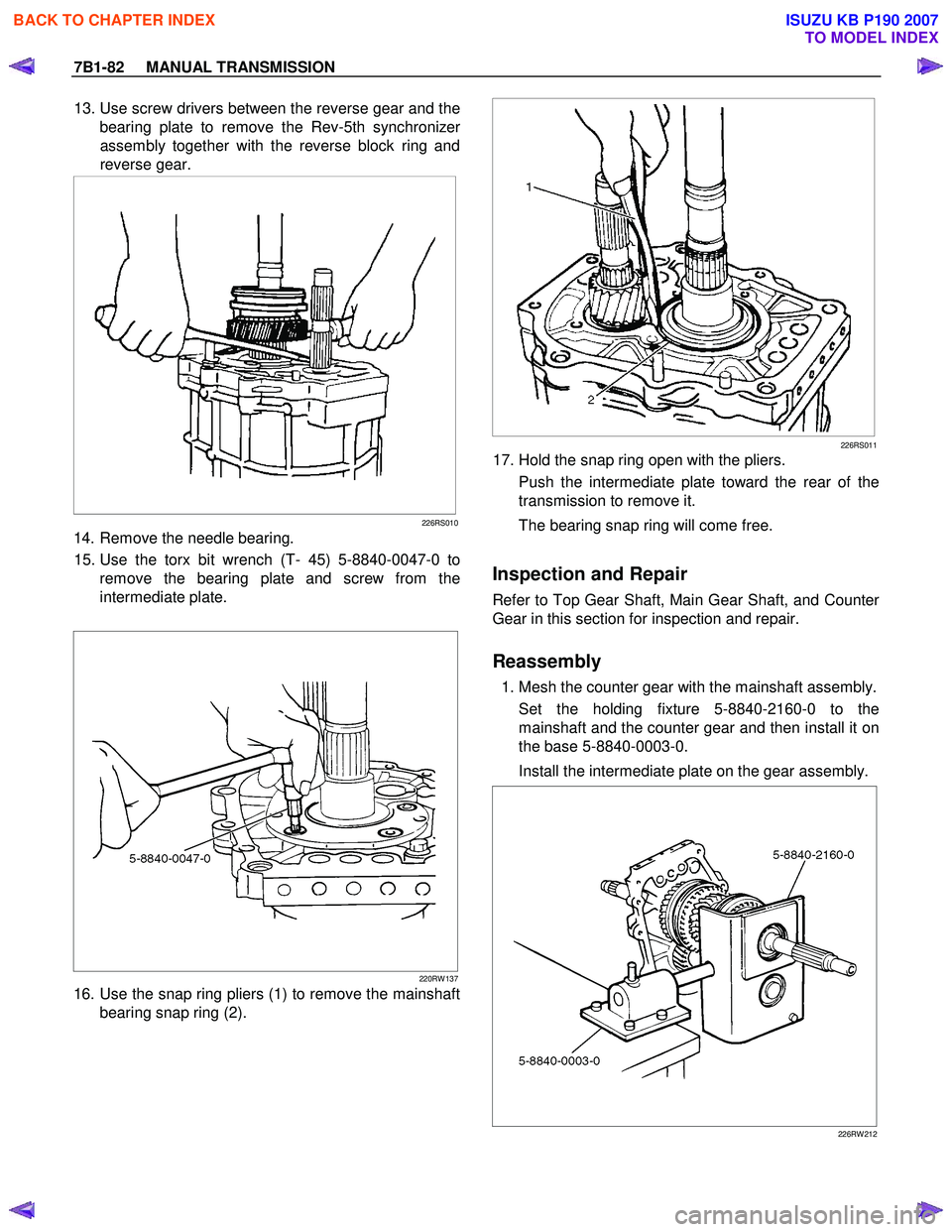
13. Use screw drivers between the reverse gear and the
bearing plate to remove the Rev-5th synchronize
r
assembly together with the reverse block ring and
reverse gear.
226RS010
14. Remove the needle bearing.
15. Use the torx bit wrench (T- 45) 5-8840-0047-0 to remove the bearing plate and screw from the
intermediate plate.
220RW 137
16. Use the snap ring pliers (1) to remove the mainshaft bearing snap ring (2).
226RS011
17. Hold the snap ring open with the pliers.
Push the intermediate plate toward the rear of the
transmission to remove it.
The bearing snap ring will come free.
Inspection and Repair
Refer to Top Gear Shaft, Main Gear Shaft, and Counter
Gear in this section for inspection and repair.
Reassembly
1. Mesh the counter gear with the mainshaft assembly. Set the holding fixture 5-8840-2160-0 to the
mainshaft and the counter gear and then install it on
the base 5-8840-0003-0.
Install the intermediate plate on the gear assembly.
226RW 212
BACK TO CHAPTER INDEX
TO MODEL INDEX
ISUZU KB P190 2007
Page 4689 of 6020
MANUAL TRANSMISSION 7B1-83
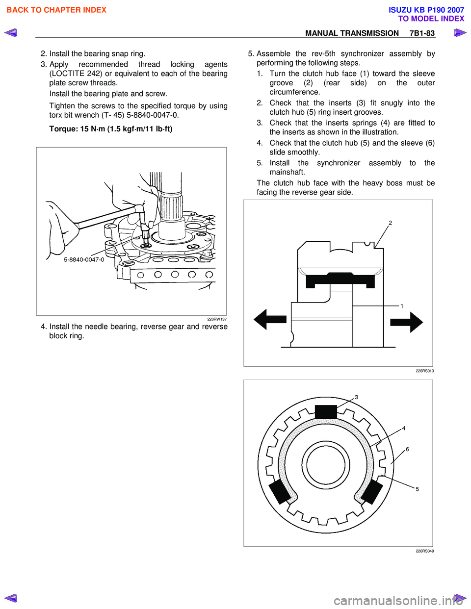
2. Install the bearing snap ring.
3.
Apply recommended thread locking agents
(LOCTITE 242) or equivalent to each of the bearing
plate screw threads.
Install the bearing plate and screw.
Tighten the screws to the specified torque by using
torx bit wrench (T- 45) 5-8840-0047-0.
Torque: 15 N ⋅
⋅⋅
⋅
m (1.5 kgf ⋅
⋅⋅
⋅
m/11 lb ⋅
⋅⋅
⋅
ft)
220RW 137
4. Install the needle bearing, reverse gear and reverse block ring. 5. Assemble the rev-5th synchronizer assembly b
y
performing the following steps.
1. Turn the clutch hub face (1) toward the sleeve groove (2) (rear side) on the oute
r
circumference.
2. Check that the inserts (3) fit snugly into the clutch hub (5) ring insert grooves.
3. Check that the inserts springs (4) are fitted to the inserts as shown in the illustration.
4. Check that the clutch hub (5) and the sleeve (6) slide smoothly.
5. Install the synchronizer assembly to the mainshaft.
The clutch hub face with the heavy boss must be
facing the reverse gear side.
226RS013
226RS049
BACK TO CHAPTER INDEX
TO MODEL INDEX
ISUZU KB P190 2007
Page 4729 of 6020
7B1-10 Manual Transmission (MUX)
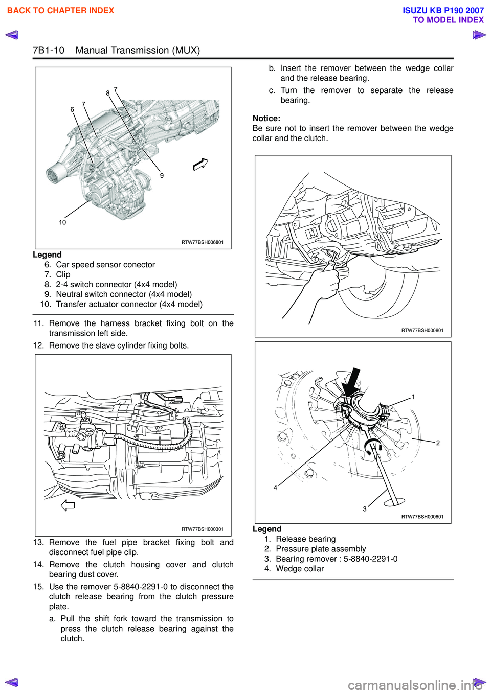
Legend6. Car speed sensor conector
7. Clip
8. 2-4 switch connector (4x4 model)
9. Neutral switch connector (4x4 model)
10. Transfer actuator connector (4x4 model)
11. Remove the harness bracket fixing bolt on the transmission left side.
12. Remove the slave cylinder fixing bolts.
13. Remove the fuel pipe bracket fixing bolt and disconnect fuel pipe clip.
14. Remove the clutch housing cover and clutch bearing dust cover.
15. Use the remover 5-8840-2291-0 to disconnect the clutch release bearing from the clutch pressure
plate.
a. Pull the shift fork toward the transmission to press the clutch release bearing against the
clutch. b. Insert the remover between the wedge collar
and the release bearing.
c. Turn the remover to separate the release bearing.
Notice:
Be sure not to insert the remover between the wedge
collar and the clutch.
Legend 1. Release bearing
2. Pressure plate assembly
3. Bearing remover : 5-8840-2291-0
4. Wedge collar
RTW77BSH006801
10 9
6
7 8
7
RTW77BSH000301
RTW77BSH000801
RTW77BSH000601
1
3
4
2
BACK TO CHAPTER INDEX
TO MODEL INDEX
ISUZU KB P190 2007
Page 4731 of 6020
7B1-12 Manual Transmission (MUX)
22. Remove the transmission retaining nuts and bolts.Remove the transmission assembly (4x2 model) or
the transmission & transfer assembly (4x4 model)
from the vehicle.
23. Remove the transmission-transfer fixing bolts and nut, and disassemble the transfer from the
transmission. (4x4 model)
Installation
1. Apply grease (BESCO L-2 or equivalent) on the splined portion of the output shaft.
2. Connect the transfer to the transmission. (4x4 model)
3. Install the transmission-transfer fixing bolts and nut, and tighten them to the specified torque. (4x4
model)
Torque: 41 N ⋅m (4.2 kgf ⋅m/30 lb ⋅ft)
4. Apply a thin coat of molybdenum disulfide grease on the splined portion of the input shaft spline.
5. Slowly operate the transmission jack until the front of transmission is aligned with the rear of the
engine.
6. Align the input shaft spline with the clutch driven plate spline.
7. Install the transmission assembly (4x2 model) or the transmission & transfer assembly (4x4 model)
to the engine.
• Tighten the transmission bolts to the specified torque.
Torque: 76 N ⋅m (7.7 kgf ⋅m/56 lb ⋅ft)
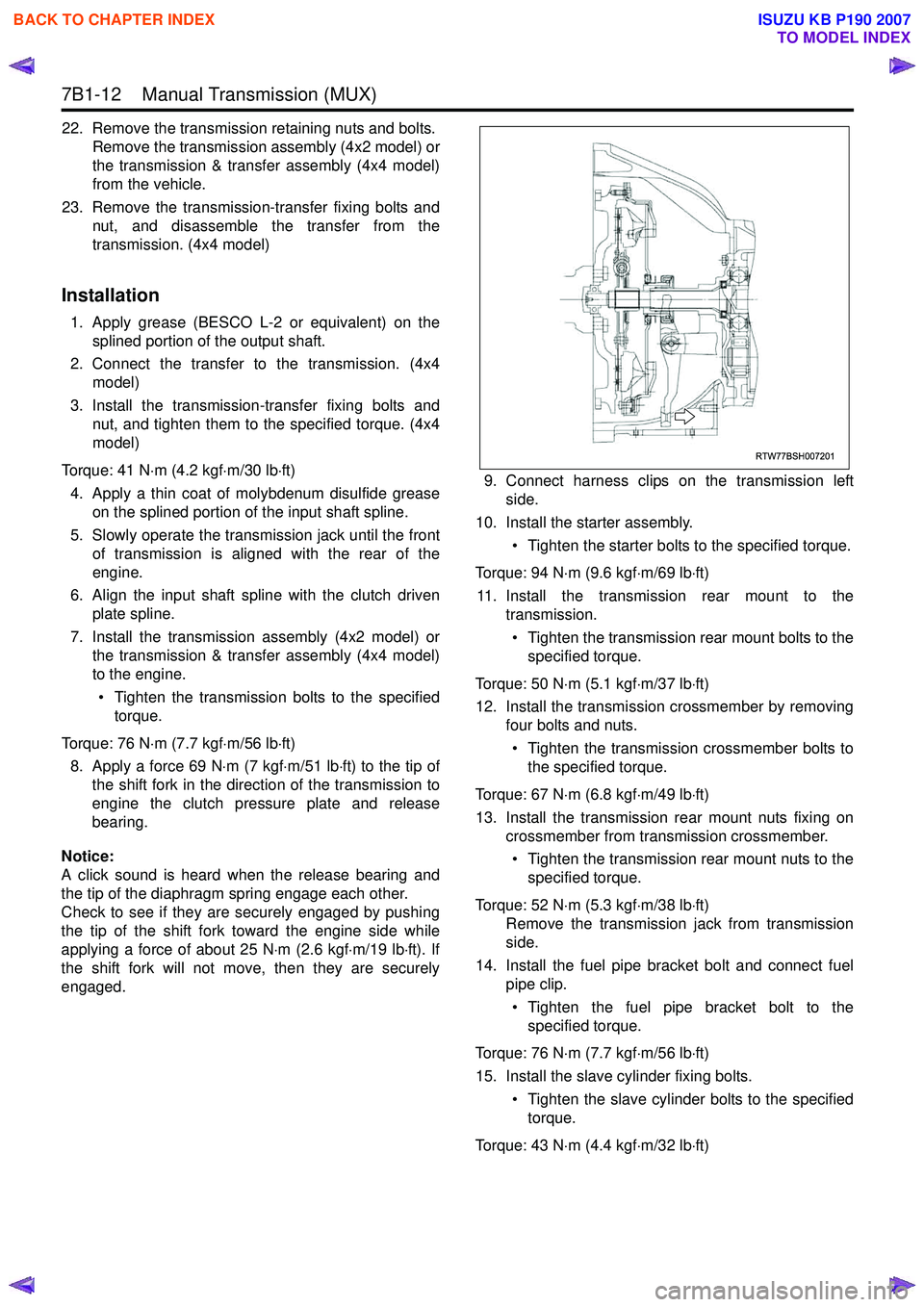
8. Apply a force 69 N ⋅m (7 kgf ⋅m/51 lb ⋅ft) to the tip of
the shift fork in the direction of the transmission to
engine the clutch pressure plate and release
bearing.
Notice:
A click sound is heard when the release bearing and
the tip of the diaphragm spring engage each other.
Check to see if they are securely engaged by pushing
the tip of the shift fork toward the engine side while
applying a force of about 25 N ⋅m (2.6 kgf ⋅m/19 lb ⋅ft). If
the shift fork will not move, then they are securely
engaged. 9. Connect harness clips on the transmission left
side.
10. Install the starter assembly.
• Tighten the starter bolts to the specified torque.
Torque: 94 N ⋅m (9.6 kgf ⋅m/69 lb ⋅ft)
11. Install the transmission rear mount to the transmission.
• Tighten the transmission rear mount bolts to the specified torque.
Torque: 50 N ⋅m (5.1 kgf ⋅m/37 lb ⋅ft)
12. Install the transmission crossmember by removing four bolts and nuts.
• Tighten the transmission crossmember bolts to the specified torque.
Torque: 67 N ⋅m (6.8 kgf ⋅m/49 lb ⋅ft)
13. Install the transmission rear mount nuts fixing on crossmember from transmission crossmember.
• Tighten the transmission rear mount nuts to the specified torque.
Torque: 52 N ⋅m (5.3 kgf ⋅m/38 lb ⋅ft)
Remove the transmission jack from transmission
side.
14. Install the fuel pipe bracket bolt and connect fuel pipe clip.
• Tighten the fuel pipe bracket bolt to the specified torque.
Torque: 76 N ⋅m (7.7 kgf ⋅m/56 lb ⋅ft)
15. Install the slave cylinder fixing bolts. • Tighten the slave cylinder bolts to the specifiedtorque.
Torque: 43 N ⋅m (4.4 kgf ⋅m/32 lb ⋅ft)
RTW77BSH007201
BACK TO CHAPTER INDEX
TO MODEL INDEX
ISUZU KB P190 2007
Page 4741 of 6020
7B1-22 Manual Transmission (MUX)
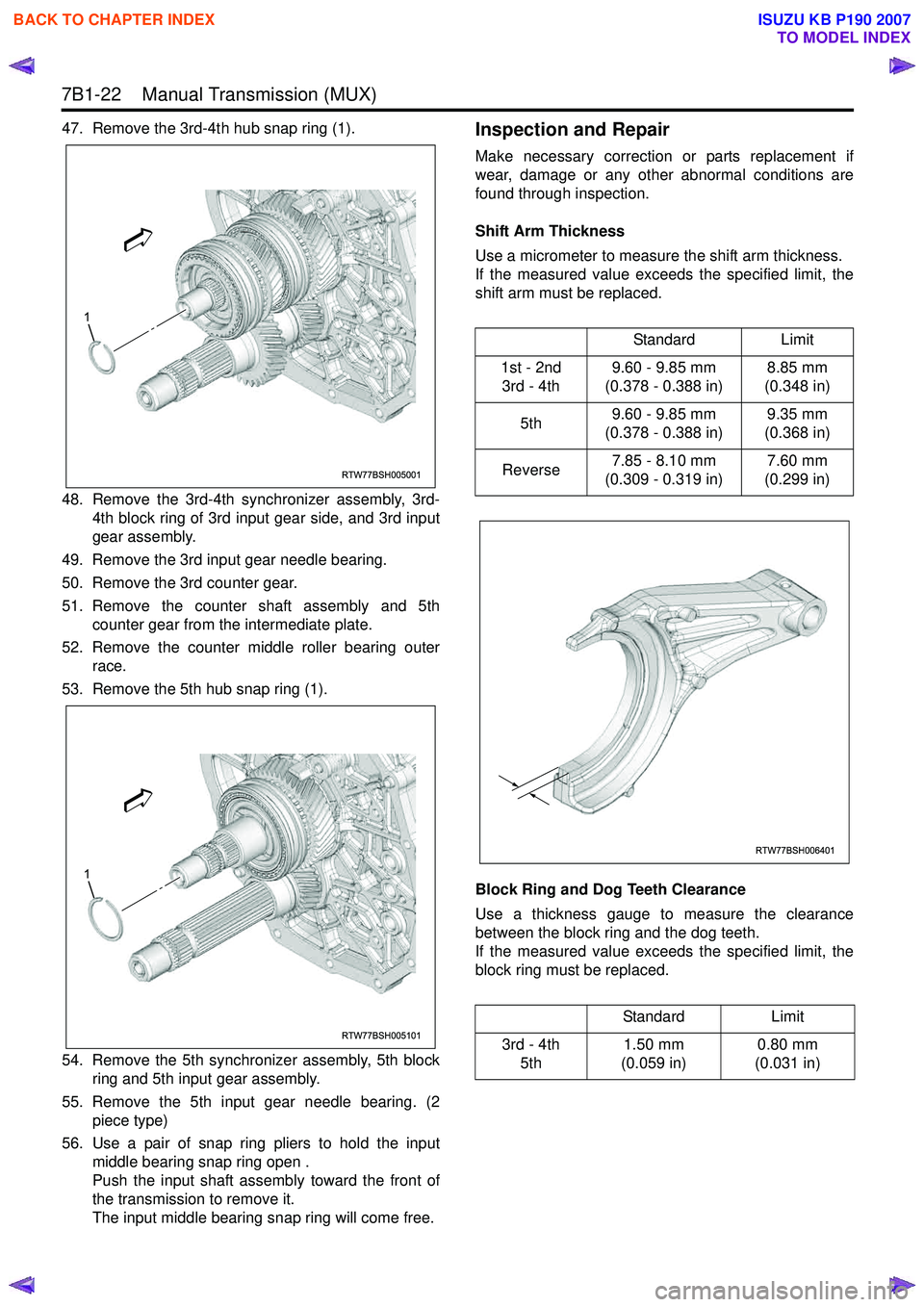
47. Remove the 3rd-4th hub snap ring (1).
48. Remove the 3rd-4th synchronizer assembly, 3rd-4th block ring of 3rd input gear side, and 3rd input
gear assembly.
49. Remove the 3rd input gear needle bearing.
50. Remove the 3rd counter gear.
51. Remove the counter shaft assembly and 5th counter gear from the intermediate plate.
52. Remove the counter middle roller bearing outer race.
53. Remove the 5th hub snap ring (1).
54. Remove the 5th synchronizer assembly, 5th block ring and 5th input gear assembly.
55. Remove the 5th input gear needle bearing. (2 piece type)
56. Use a pair of snap ring pliers to hold the input middle bearing snap ring open .
Push the input shaft assembly toward the front of
the transmission to remove it.
The input middle bearing snap ring will come free.Inspection and Repair
Make necessary correction or parts replacement if
wear, damage or any other abnormal conditions are
found through inspection.
Shift Arm Thickness
Use a micrometer to measure the shift arm thickness.
If the measured value exceeds the specified limit, the
shift arm must be replaced.
Block Ring and Dog Teeth Clearance
Use a thickness gauge to measure the clearance
between the block ring and the dog teeth.
If the measured value exceeds the specified limit, the
block ring must be replaced.
RTW77BSH005001
1
RTW77BSH005101
1
Standard Limit
1st - 2nd 3rd - 4th 9.60 - 9.85 mm
(0.378 - 0.388 in) 8.85 mm
(0.348 in)
5th 9.60 - 9.85 mm
(0.378 - 0.388 in) 9.35 mm
(0.368 in)
Reverse 7.85 - 8.10 mm
(0.309 - 0.319 in) 7.60 mm
(0.299 in)
Standard Limit
3rd - 4th 5th 1.50 mm
(0.059 in) 0.80 mm
(0.031 in)
RTW77BSH006401
BACK TO CHAPTER INDEX
TO MODEL INDEX
ISUZU KB P190 2007