2007 ISUZU KB P190 tow
[x] Cancel search: towPage 3275 of 6020
Engine Management – V6 – General Information Page 6C1-1–33
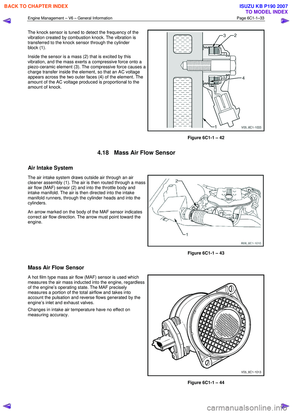
The knock sensor is tuned to detect the frequency of the
vibration created by combustion knock. The vibration is
transferred to the knock sensor through the cylinder
block (1).
Inside the sensor is a mass (2) that is excited by this
vibration, and the mass exerts a compressive force onto a
piezo-ceramic element (3). The compressive force causes a
charge transfer inside the element, so that an AC voltage
appears across the two outer faces (4) of the element. The
amount of the AC voltage produced is proportional to the
amount of knock.
Figure 6C1-1 – 42
4.18 Mass Air Flow Sensor
Air Intake System
The air intake system draws outside air through an air
cleaner assembly (1). The air is then routed through a mass
air flow (MAF) sensor (2) and into the throttle body and
intake manifold. The air is then directed into the intake
manifold runners, through the cylinder heads and into the
cylinders.
An arrow marked on the body of the MAF sensor indicates
correct air flow direction. The arrow must point toward the
engine.
Figure 6C1-1 – 43
Mass Air Flow Sensor
A hot film type mass air flow (MAF) sensor is used which
measures the air mass inducted into the engine, regardless
of the engine’s operating state. The MAF precisely
measures a portion of the total airflow and takes into
account the pulsation and reverse flows generated by the
engine’s inlet and exhaust valves.
Changes in intake air temperature have no effect on
measuring accuracy.
Figure 6C1-1 – 44
BACK TO CHAPTER INDEX
TO MODEL INDEX
ISUZU KB P190 2007
Page 3302 of 6020
Engine Management – V6 – Diagnostics Page 6C1-2–24
Checks Actions
Temperature Related Temperature related intermittent fault condition occurs only when the engine or ambient
temperature is hot, or only when it is cold.
• If the intermittent fault is heat related, review Tech 2 data in relationship to the
following:
• high ambient temperature,
• engine generated heat,
• circuit generated heat due to a poor electrical connection or high electrical
load, and
• higher than normal load conditions (towing, etc.).
• If the intermittent fault is related to cold ambient or engine temperature, review
Tech 2 data in relationship to the following:
• low ambient temperature, and
• the fault condition that occurs only on a cold start situation.
Additional Tests
• Incorrect installation of aftermarket electrical equipment such as the following:
• mobile phones,
• theft deterrent alarms,
• lights, or
• radio equipment.
• Electromagnetic interference (EMI) caused by a faulty relay, ECM controlled
solenoid or switch. The fault is triggered when the relay or solenoid is activated.
• Test the A/C compressor clutch and some relays that contain a clamping diode or
resistor for an open circuit.
• Test the generator for a faulty rectifier bridge that may allow the A/C noise into the
ECM electrical circuit.
When all diagnosis and repairs are completed, check the system for correct operation.
5.3 Backfire
Description
The air / fuel mixture in the intake manifold or in the exhaust system ignites which produces a loud popping noise.
Checks Actions
Preliminary Perform the Preliminary Checks. Refer to 4.3 Preliminary Checks in this
Section.
Sensor / System • Check the air intake system and crankcase for air leaks.
• Check the PCV System for correct operation. Refer to 6A1 Engine Mechanical –
V6.
• Use Tech 2 to monitor the knock sensor system for excessive spark retard
activity. Check for items that cause spark retard activity.
BACK TO CHAPTER INDEX
TO MODEL INDEX
ISUZU KB P190 2007
Page 3310 of 6020
Engine Management – V6 – Diagnostics Page 6C1-2–32
Checks Actions
Ignition System
• Inspect for moisture or corrosion around the spark plug / ignition coil area.
• Test the ignition coil voltage output. Refer to 6C1-3 Engine Management – V6 –
Service Operations.
• Remove and inspect the spark plugs. Refer to 6C1-3 Engine Management – V6 –
Service Operations.
NOTE
If the spark plugs are fouled, determine the cause of the fouling before
replacing the spark plugs, refer to 6C1-3 Engine Management – V6 –
Service Operations.
• Check for loose ignition coil ground circuit.
Engine Mechanical
• Check for the following engine mechanical fault condition. Refer to 6A1 Engine
Mechanical – V6.
• low engine compression, and
• worn valve train components.
Additional Checks
• Check the exhaust system for possible restrictions. Refer to 6F Exhaust System –
V6.
• Test for other TCM related faults that may cause the transmission to operate in
the default mode.
• Check for transmission mechanical faults that may produce similar symptoms
such as slipping clutch.
When all diagnosis and repairs are completed, check the system for correct operation.
5.11 Poor Fuel Economy
Description
As confirmed by an actual road test, the fuel economy as compared to the previous fuel consumption of the same
vehicle is noticeably lower.
Checks Actions
Preliminary • Perform the preliminary checks. Refer to 4.3 Preliminary Checks in this
Section.
• Check the air filter element and intake air ducts for blockages.
• Check for correct tyre pressure. Refer to the Owners Manual.
• Check the recent driving conditions are the same compared to the previous when
the fuel consumption is normal. The following are list of driving conditions that
may affect fuel consumption:
− vehicle load,
− acceleration rate,
− A/C or other electrical equipment use, and
− vehicle used for towing.
BACK TO CHAPTER INDEX
TO MODEL INDEX
ISUZU KB P190 2007
Page 3529 of 6020
Engine Management – V6 – Service Operations Page 6C1-3–5
• Ensure the correct procedure for disconnecting and connecting engine management system wiring connectors is
always followed.
• Ensure that all wiring connectors are fitted correctly.
• The engine management system wiring connectors are designed to fit only one way; there are indexing tabs and
slots on both halves of the connector. Forcing the connector into place is not necessary if it is being installed with
the correct orientation. Failure to take care to match the indexing tabs and slots correctly can cause damage to the
connector, the module, or other vehicle components or systems.
• Never touch the connector pins of any electronic component, such as an ECM, as electrostatic discharge (ESD)
damage may result.
• W hen steam or pressure cleaning engines, do not direct the cleaning nozzle at engine management system
components.
• Never subject the ECM to temperatures less than -40 ° C and greater than 125 ° C.
• Prior to disconnection or removal of any components associated with the fuel system, clean the area around any
connection points to avoid possible contamination of the fuel system.
• A depressurised fuel system contains fuel in the fuel system and fuel lines that can be spilled during service
operations. To reduce the chance of personal injury, cover the fittings with a shop towel to absorb any fuel spillage
prior to performing the service operation. Once the service operation has been completed, place the towel in an
approved container for disposal.
• To avoid accidental fuel discharge, it is advisable to disconnect the battery and remove the fuel pump relay if the
fuel line between the fuel pump and the fuel rail is to be disconnected / open for an indefinite period.
• Always tighten fasteners to the correct tightening torque, and where indicated in the service procedure, follow the
correct tightening sequence, precautions and recommendations to prevent premature failure of the fastener or
component.
• After removing components, such as the upper or lower intake manifold, front engine pipe, heated oxygen sensor,
etc. always plug any openings to prevent dirt and other contaminants from entering.
• Do not use silicone based assembly lubricants as damage to the heated oxygen sensors may result.
Use of incorrect electrical test equipment
when performing engine management service
procedures could result in incorrect results or
component damage.
• Use only the test equipment specified in the diagnostic tables. Use of other test equipment may either give
incorrect results or damage serviceable components, refer to, 6C1-2 Engine Management – V6 – Diagnostics.
• After completing the required service operations, road test the vehicle to ensure correct engine management
system operation.
Service Requirements
Basic Knowledge Required
A lack of basic understanding of electronics,
electrical wiring circuits and use of electrical
circuit testing tools when performing certain
service procedures could result in incorrect
results or damage to components.
In addition, a general understanding of the engine management system and its component operation is essential to
prevent misdiagnosis and component damage.
BACK TO CHAPTER INDEX
TO MODEL INDEX
ISUZU KB P190 2007
Page 3548 of 6020
Engine Management – V6 – Service Operations Page 6C1-3–24
Clean the area around the engine oil pressure
sensor before removal to avoid debris from
entering the engine.
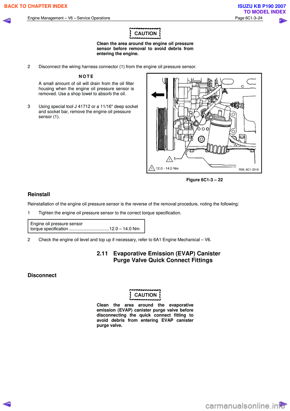
2 Disconnect the wiring harness connector (1) from the engine oil pressure sensor. NOTE
A small amount of oil will drain from the oil filter
housing when the engine oil pressure sensor is
removed. Use a shop towel to absorb the oil.
3 Using special tool J 41712 or a 11/16" deep socket and socket bar, remove the engine oil pressure
sensor (1).
Figure 6C1-3 – 22
Reinstall
Reinstallation of the engine oil pressure sensor is the reverse of the removal procedure, noting the following:
1 Tighten the engine oil pressure sensor to the correct torque specification.
Engine oil pressure sensor
torque specification .................................12.0 – 14.0 Nm
2 Check the engine oil level and top up if necessary, refer to 6A1 Engine Mechanical – V6.
2.11 Evaporative Emission (EVAP) Canister Purge Valve Quick Connect Fittings
Disconnect
Clean the area around the evaporative
emission (EVAP) canister purge valve before
disconnecting the quick connect fitting to
avoid debris from entering EVAP canister
purge valve.
BACK TO CHAPTER INDEX
TO MODEL INDEX
ISUZU KB P190 2007
Page 3571 of 6020
Engine Management – V6 – Service Operations Page 6C1-3–47
2.21 Schrader Valve – Fuel Pressure Gauge
Connection Point
If the Schrader valve is to be removed but not
replaced immediately, it is advisable to
disconnect the battery to avoid possible fuel
discharge if an accidental attempt is made to
start the engine.
Disconnection of the battery affects vehicle
electronic systems. Refer to 6D1-3 Battery –
V6 before disconnecting the battery.
Remove
1 Depressurise the fuel system, refer to 6C Fuel System - V6.
2 Turn the ignition off.
A small amount of fuel may be released when
servicing the fuel pressure test point. To
reduce the chance of personal injury, cover
the fuel pressure test point with a shop towel
to absorb any fuel spillage when the Schrader
valve sealing cap and Schrader valve are
removed. After the procedure, place the towel
in an approved container for disposal.
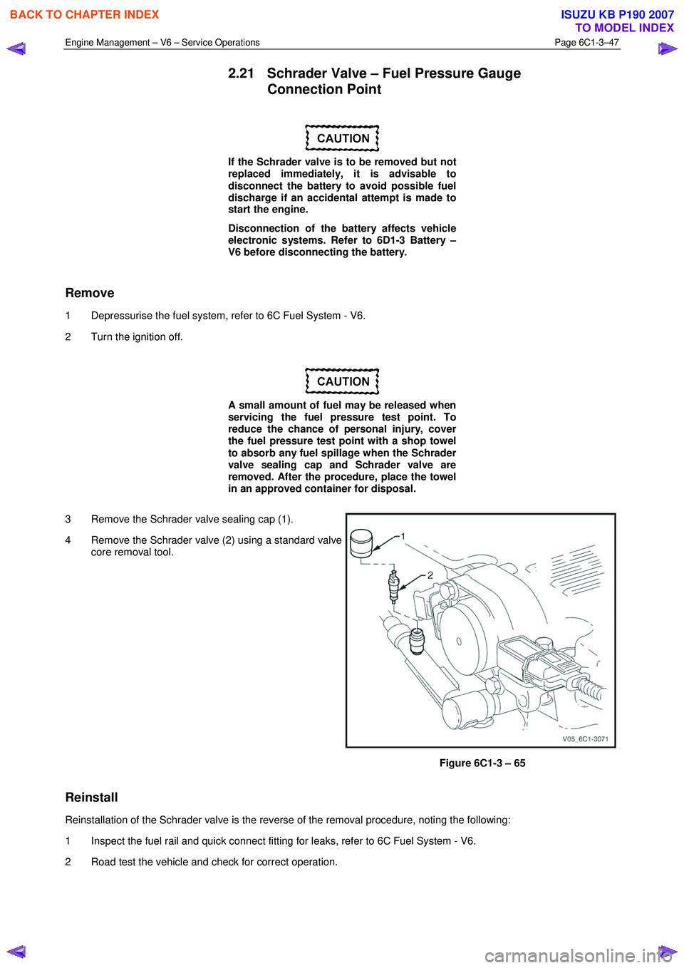
3 Remove the Schrader valve sealing cap (1).
4 Remove the Schrader valve (2) using a standard valve core removal tool.
Figure 6C1-3 – 65
Reinstall
Reinstallation of the Schrader valve is the reverse of the removal procedure, noting the following:
1 Inspect the fuel rail and quick connect fitting for leaks, refer to 6C Fuel System - V6.
2 Road test the vehicle and check for correct operation.
BACK TO CHAPTER INDEX
TO MODEL INDEX
ISUZU KB P190 2007
Page 3579 of 6020
Engine Management – V6 – Service Operations Page 6C1-3–55
Inspect
The following throttle body inspection procedure may be carried out with the throttle body installed on the vehicle. Prior to
performing a throttle body on-vehicle inspection:
• Turn the ignition switch off.
• Disconnect the throttle body wiring harness connector. Refer to Remove in this Section.
• Remove the air intake duct, refer to 2.16 Intake Air Duct Assembly.
To avoid serious personal injury, never
attempt to rotate the throttle plate manually
whilst the throttle body harness connector is
connected to the throttle body.
1 Fully open the throttle plate by hand and inspect the throttle body bore and throttle plate for any deposits.
When cleaning / inspecting the throttle body:
• Do not subject the throttle body assembly
to an immersion cleaner or a strong
solvent. Damage to the throttle position
sensor and / or sealed throttle shaft
bearings will result.
• Never use a wire brush or scraper to clean
the throttle body. A wire brush or sharp
tool may damage the throttle body
components.
2 Use a clean shop towel and a spray type hydro-carbon cleaner to clean the throttle body bore and throttle plate. If necessary, use a parts cleaning brush to remove heavy deposits.
3 Inspect the throttle body for a binding throttle plate by fully opening and closing the throttle plate by hand. It should open and close smoothly.
4 Inspect the throttle body for a bent or damaged throttle plate, cracks, corrosion, or distortion in the throttle body housing.
NOTE
The throttle body contains no serviceable parts
and should not be disassembled. If the throttle
body is damaged it must be replaced as an
assembly.
5 If the throttle body is affected by any of the above conditions, it must be replaced.
6 If an on-vehicle throttle body inspection was performed, perform the following:
• Reinstall the air intake duct, refer to 2.16 Intake Air Duct Assembly.
• Reconnect the throttle body wiring harness connector, refer to Reinstall in this Section.
• Road test the vehicle and check for correct operation, taking particular note that no air leaks are evident.
Reinstall
Reinstallation of the throttle body assembly is the reverse of the removal procedure, noting the following:
1 Ensure the throttle body and upper intake manifold mating surfaces are clean and free of foreign material.
2 Install a new throttle body to upper intake manifold gasket.
BACK TO CHAPTER INDEX
TO MODEL INDEX
ISUZU KB P190 2007
Page 3656 of 6020
Battery Page 6D1-3–16
NOTE
Charging a battery at higher current rates can
significantly reduce the life of the battery.
Charge Rate Initial Current Maximum Time Required
Slow charge 4 A 24 hours
Fast charge 35 A 2 hours
6 After a few minutes, check the colour and specific gravity of the electrolyte. Refer to 3.3 Hydrometer Test.
7 Monitor the electrolyte temperature while the battery is charging. If the electrolyte temperature reaches 55 °C:
a switch the charging current off,
b allow the battery to cool,
c reduce the charging current, and
d restart charging the battery.
NOTE
For the best results, charge the battery with the
electrolyte and plates at room temperature. An
extremely cold battery may not appear to accept
current for several hours after starting the battery
charger. If the battery does not appear to accept
charge after several hours replace the battery.
8 For slow charging check the voltage and specific gravity each hour or more regularly for fast charging. Stop the charging when there is no change in voltage or electrolyte specific gravity over three checks.
9 If the battery was fast charged connect the battery to a slow-charger for a few hours to bring the battery to the fully charged condition. Ensure the last few hours of charge do not exceed 1 A.
10 Tighten the filler caps. Ensure they are secure.
11 Install the battery in the vehicle. Refer to 4.1 Battery.
4.3 Emergency Jump Starting Procedure
Safety Precautions
• Read and obey the general safety precautions for working with batteries, refer to 2 Safety Precautions.
• Do not allow the vehicles to touch each other during the jump starting procedure.
• Ensure the assisting vehicle battery has the same voltage rating and connects negative to ground. If this is not the
case, serious injury and damage to electrical equipment can result.
• Do not push or tow the vehicle to start it. Damage can result when unburnt fuel reaches the catalytic converter and
ignites.
• Do not start the vehicle using a fast charger.
• W hen using jumper leads, treat both the booster battery and the discharged battery with care.
• Do not allow sparks, flame or smoking near the battery.
• Ensure that metal tools or jumper cables do not simultaneously contact the battery positive terminal and any other
metal part of the vehicle.
Jump Starting Procedure
1 Position the assisting vehicle so the batteries of both vehicles are close together, refer to Figure 6D1-3 – 10.
2 Apply the park brake on both vehicles.
3 Ensure that P (park) is selected for automatic transmission and N (neutral) is selected for manual transmissions.
BACK TO CHAPTER INDEX
TO MODEL INDEX
ISUZU KB P190 2007