Page 2440 of 6020
6E–270 ENGINE DRIVEABILITY AND EMISSIONS
FUEL PRESSURE RELIEF
Caution: To reduce the risk of fire and personal
injury, it is necessary to relieve the fuel system
pressure before servicing the fuel system
components.
Caution: After relieving the fuel system pressure, a
small amount of fuel may be released when
servicing fuel lines or connections. Reduce the
chance of personal injury by covering the fuel line
fitting with a short towel before disconnecting the
fittings. The towel will absorb any fuel that may leak
out. When the disconnect is completed, place the
towel in an approved container.
1. Remove the fuel filler cap.
2. Remove the fuel pump relay from the underhood relay box.
3. Start the engine and allow it to stall.
4. Crank the engine for about 30 seconds.
5. Disconnect the negative battery cable.
FUEL RAIL ASSEMBLY
Removal Procedure
NOTE:
• Use care when removing the fuel rail assembly in order to prevent damage to the injector al connector
terminal and the injector spray tips.
• Fitting should be capped and holes plugged during servicing to prevent dirt and other contaminants from
entering open lines and passage.
Important: An eight-digit identification number is
stamped on side of the fuel injector. Refer to this
number when you service the fuel rail or when a
replacement part is required.
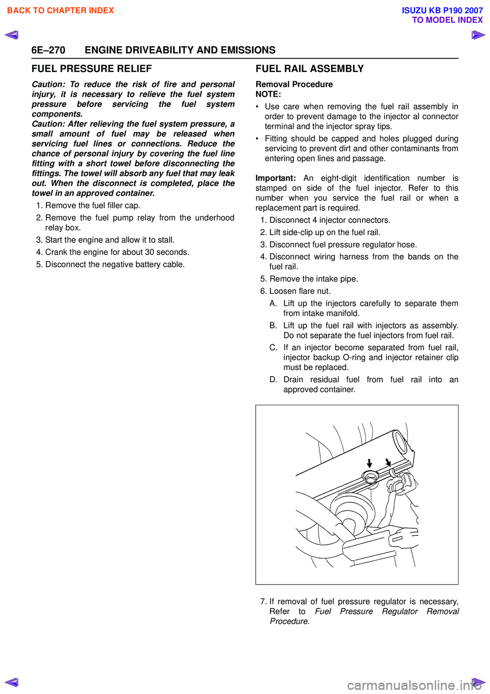
1. Disconnect 4 injector connectors.
2. Lift side-clip up on the fuel rail.
3. Disconnect fuel pressure regulator hose.
4. Disconnect wiring harness from the bands on the fuel rail.
5. Remove the intake pipe.
6. Loosen flare nut.
A. Lift up the injectors carefully to separate them from intake manifold.
B. Lift up the fuel rail with injectors as assembly. Do not separate the fuel injectors from fuel rail.
C. If an injector become separated from fuel rail, injector backup O-ring and injector retainer clip
must be replaced.
D. Drain residual fuel from fuel rail into an approved container.
7. If removal of fuel pressure regulator is necessary, Refer to Fuel Pressure Regulator Removal
Procedure .
BACK TO CHAPTER INDEX
TO MODEL INDEX
ISUZU KB P190 2007
Page 2443 of 6020
ENGINE DRIVEABILITY AND EMISSIONS 6E–273
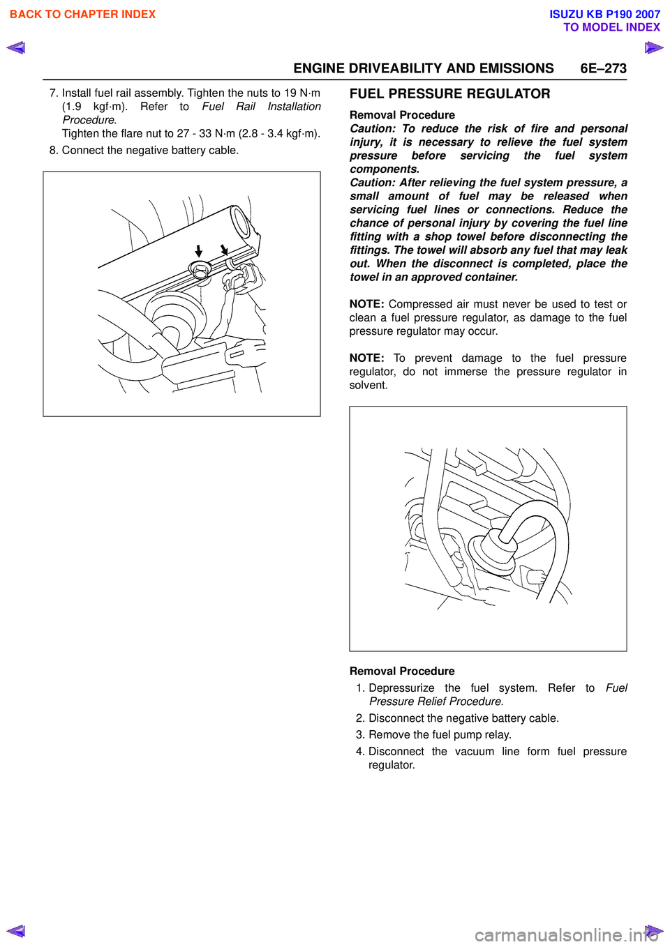
7. Install fuel rail assembly. Tighten the nuts to 19 N·m(1.9 kgf·m). Refer to Fuel Rail Installation
Procedure .
Tighten the flare nut to 27 - 33 N·m (2.8 - 3.4 kgf·m).
8. Connect the negative battery cable.FUEL PRESSURE REGULATOR
Removal Procedure
Caution: To reduce the risk of fire and personal
injury, it is necessary to relieve the fuel system
pressure before servicing the fuel system
components.
Caution: After relieving the fuel system pressure, a
small amount of fuel may be released when
servicing fuel lines or connections. Reduce the
chance of personal injury by covering the fuel line
fitting with a shop towel before disconnecting the
fittings. The towel will absorb any fuel that may leak
out. When the disconnect is completed, place the
towel in an approved container.
NOTE: Compressed air must never be used to test or
clean a fuel pressure regulator, as damage to the fuel
pressure regulator may occur.
NOTE: To prevent damage to the fuel pressure
regulator, do not immerse the pressure regulator in
solvent.
Removal Procedure
1. Depressurize the fuel system. Refer to Fuel
Pressure Relief Procedure.
2. Disconnect the negative battery cable.
3. Remove the fuel pump relay.
4. Disconnect the vacuum line form fuel pressure regulator.
BACK TO CHAPTER INDEX
TO MODEL INDEX
ISUZU KB P190 2007
Page 2627 of 6020
Engine Mechanical – V6 Page 6A1–148
3 Observe the markings (1) on the bearing caps. Each
bearing cap is marked to identify its location. The
markings have the following meanings:
• The raised feature must always be oriented
toward the centre of the cylinder head.
• An I indicates the intake camshaft.
• An E indicates the exhaust camshaft.
• The number indicates the journal position from
the front of the engine.
Figure 6A1 – 239
4 Remove the camshaft bearing cap bolts (1) and caps (2).
Figure 6A1 – 240
5 Remove the camshafts (1).
Figure 6A1 – 241
BACK TO CHAPTER INDEX
TO MODEL INDEX
ISUZU KB P190 2007
Page 2628 of 6020
Engine Mechanical – V6 Page 6A1–149
Left-hand Side
1 Remove the left-hand cylinder head camshaft position actuators, refer to 3.18 Camshaft Sprocket.
2 Remove Tool No. EN-46105 – 1 (1) from the left-hand camshafts.
NOTE
Tool No. EN-46105 was installed as part of the
left-hand cylinder head camshaft position
actuator removal procedure.
Figure 6A1 – 242
3 Observe the markings (1) on the bearing caps. Each bearing cap is marked in order to identify its location.
The markings have the following meanings:
• The raised feature must always be oriented
toward the centre of the cylinder head.
• An I indicates the intake camshaft.
• An E indicates the exhaust camshaft.
• The number indicates the journal position from
the front of the engine.
Figure 6A1 – 243
4 Remove the camshaft bearing cap bolts (1) and caps (2).
Figure 6A1 – 244
BACK TO CHAPTER INDEX
TO MODEL INDEX
ISUZU KB P190 2007
Page 2633 of 6020
Engine Mechanical – V6 Page 6A1–154
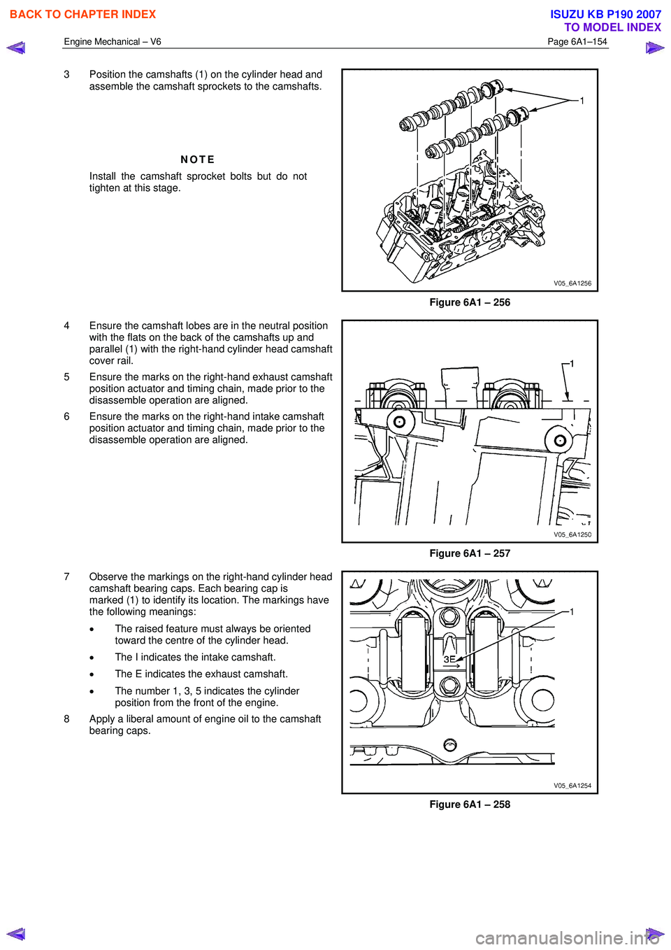
3 Position the camshafts (1) on the cylinder head and
assemble the camshaft sprockets to the camshafts.
NOTE
Install the camshaft sprocket bolts but do not
tighten at this stage.
Figure 6A1 – 256
4 Ensure the camshaft lobes are in the neutral position with the flats on the back of the camshafts up and
parallel (1) with the right-hand cylinder head camshaft
cover rail.
5 Ensure the marks on the right-hand exhaust camshaft position actuator and timing chain, made prior to the
disassemble operation are aligned.
6 Ensure the marks on the right-hand intake camshaft position actuator and timing chain, made prior to the
disassemble operation are aligned.
Figure 6A1 – 257
7 Observe the markings on the right-hand cylinder head camshaft bearing caps. Each bearing cap is
marked (1) to identify its location. The markings have
the following meanings:
• The raised feature must always be oriented
toward the centre of the cylinder head.
• The I indicates the intake camshaft.
• The E indicates the exhaust camshaft.
• The number 1, 3, 5 indicates the cylinder
position from the front of the engine.
8 Apply a liberal amount of engine oil to the camshaft bearing caps.
Figure 6A1 – 258
BACK TO CHAPTER INDEX
TO MODEL INDEX
ISUZU KB P190 2007
Page 2634 of 6020
Engine Mechanical – V6 Page 6A1–155
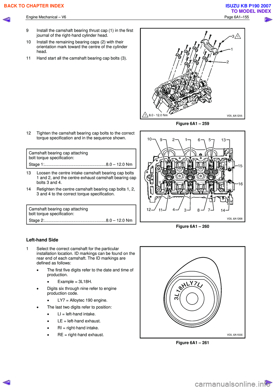
9 Install the camshaft bearing thrust cap (1) in the first
journal of the right-hand cylinder head.
10 Install the remaining bearing caps (2) with their orientation mark toward the centre of the cylinder
head.
11 Hand start all the camshaft bearing cap bolts (3).
Figure 6A1 – 259
12 Tighten the camshaft bearing cap bolts to the correct torque specification and in the sequence shown.
Camshaft bearing cap attaching
bolt torque specification:
Stage 1:.....................................................8.0 – 12.0 Nm
13 Loosen the centre intake camshaft bearing cap bolts 1 and 2, and the centre exhaust camshaft bearing cap
bolts 3 and 4.
14 Retighten the centre camshaft bearing cap bolts 1, 2, 3 and 4 to the correct torque specification.
Camshaft bearing cap attaching
bolt torque specification:
Stage 2:.....................................................8.0 – 12.0 Nm
Figure 6A1 – 260
Left-hand Side
1 Select the correct camshaft for the particular installation location. ID markings can be found on the
rear end of each camshaft. The ID markings are
defined as follows:
• The first five digits refer to the date and time of
production.
• Example = 3L18H.
• Digits six through nine refer to engine
production code.
• LY7 = Alloytec 190 engine.
• The last two digits refer to position:
• LI = left-hand intake.
• LE = left-hand exhaust.
• RI = right-hand intake.
• RE = right-hand exhaust.
Figure 6A1 – 261
BACK TO CHAPTER INDEX
TO MODEL INDEX
ISUZU KB P190 2007
Page 2636 of 6020
Engine Mechanical – V6 Page 6A1–157
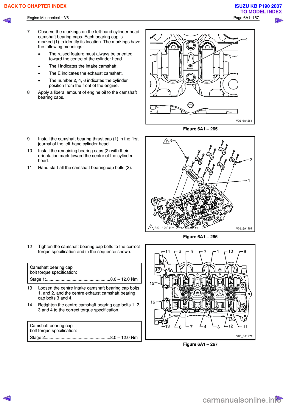
7 Observe the markings on the left-hand cylinder head
camshaft bearing caps. Each bearing cap is
marked (1) to identify its location. The markings have
the following meanings:
• The raised feature must always be oriented
toward the centre of the cylinder head.
• The I indicates the intake camshaft.
• The E indicates the exhaust camshaft.
• The number 2, 4, 6 indicates the cylinder
position from the front of the engine.
8 Apply a liberal amount of engine oil to the camshaft bearing caps.
Figure 6A1 – 265
9 Install the camshaft bearing thrust cap (1) in the first journal of the left-hand cylinder head.
10 Install the remaining bearing caps (2) with their orientation mark toward the centre of the cylinder
head.
11 Hand start all the camshaft bearing cap bolts (3).
Figure 6A1 – 266
12 Tighten the camshaft bearing cap bolts to the correct torque specification and in the sequence shown.
Camshaft bearing cap
bolt torque specification:
Stage 1:.....................................................8.0 – 12.0 Nm
13 Loosen the centre intake camshaft bearing cap bolts 1, and 2, and the centre exhaust camshaft bearing
cap bolts 3 and 4.
14 Retighten the centre camshaft bearing cap bolts 1, 2, 3 and 4 to the correct torque specification.
Camshaft bearing cap
bolt torque specification:
Stage 2:.....................................................8.0 – 12.0 Nm
Figure 6A1 – 267
BACK TO CHAPTER INDEX
TO MODEL INDEX
ISUZU KB P190 2007
Page 2655 of 6020
Engine Mechanical – V6 Page 6A1–176
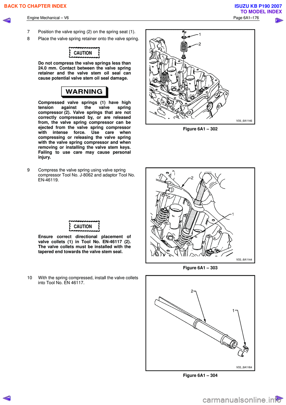
7 Position the valve spring (2) on the spring seat (1).
8 Place the valve spring retainer onto the valve spring.
CAUTION
Do not compress the valve springs less than
24.0 mm. Contact between the valve spring
retainer and the valve stem oil seal can
cause potential valve stem oil seal damage.
Compressed valve springs (1) have high
tension against the valve spring
compressor (2). Valve springs that are not
correctly compressed by, or are released
from, the valve spring compressor can be
ejected from the valve spring compressor
with intense force. Use care when
compressing or releasing the valve spring
with the valve spring compressor and when
removing or installing the valve stem keys.
Failing to use care may cause personal
injury.
Figure 6A1 – 302
9 Compress the valve spring using valve spring compressor Tool No. J-8062 and adaptor Tool No.
EN-46119.
CAUTION
Ensure correct directional placement of
valve collets (1) in Tool No. EN-46117 (2).
The valve collets must be installed with the
tapered end towards the valve stem seal.
Figure 6A1 – 303
10 W ith the spring compressed, install the valve collets into Tool No. EN 46117.
Figure 6A1 – 304
BACK TO CHAPTER INDEX
TO MODEL INDEX
ISUZU KB P190 2007