2007 ISUZU KB P190 tow
[x] Cancel search: towPage 1416 of 6020
6A-56 ENGINE MECHANICAL (4JK1/4JJ1)
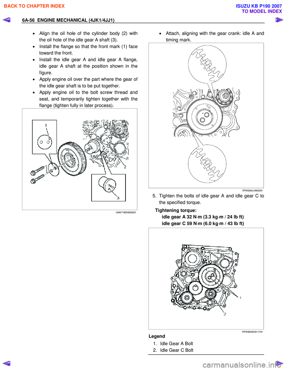
• Align the oil hole of the cylinder body (2) with
the oil hole of the idle gear A shaft (3).
• Install the flange so that the front mark (1) face
toward the front.
• Install the idle gear A and idle gear A flange,
idle gear A shaft at the position shown in the
figure.
•
Apply engine oil over the part where the gear of
the idle gear shaft is to be put together.
•
Apply engine oil to the bolt screw thread and
seat, and temporarily tighten together with the
flange (tighten fully in later process).
LNW 71BSH000501
• Attach, aligning with the gear crank: idle A and
timing mark.
RTW 56ALH000301
5. Tighten the bolts of idle gear A and idle gear C to
the specified torque.
Tightening torque: idle gear A 32 N ⋅
⋅⋅
⋅
m (3.3 kg ⋅
⋅⋅
⋅
m / 24 lb ft)
idle gear C 59 N ⋅
⋅⋅
⋅
m (6.0 kg ⋅
⋅⋅
⋅
m / 43 lb ft)
RTW 56ASH011701
Legend
1. Idle Gear A Bolt
2. Idle Gear C Bolt
BACK TO CHAPTER INDEX
TO MODEL INDEX
ISUZU KB P190 2007
Page 1462 of 6020
6A-102 ENGINE MECHANICAL (4JK1/4JJ1)
Note:
Sort the removed bearings according to cylinders b
y
using tags.
LNW 21BSH004901
8. Remove the piston and connecting rod.
• Remove carbon on the upper side of the
cylinder block with a scraper.
• Pull out the piston and connecting rod towards
the cylinder head.
Note:
Be sure not to damage the oil jet and cylinder block
when pushing out the connecting rod.
9. Remove the connecting rod bearing.
Note:
Sort the bearings in the order of cylinders when reusing
them so that they are not confused with the bearings o
f
other cylinders.
Disassembly
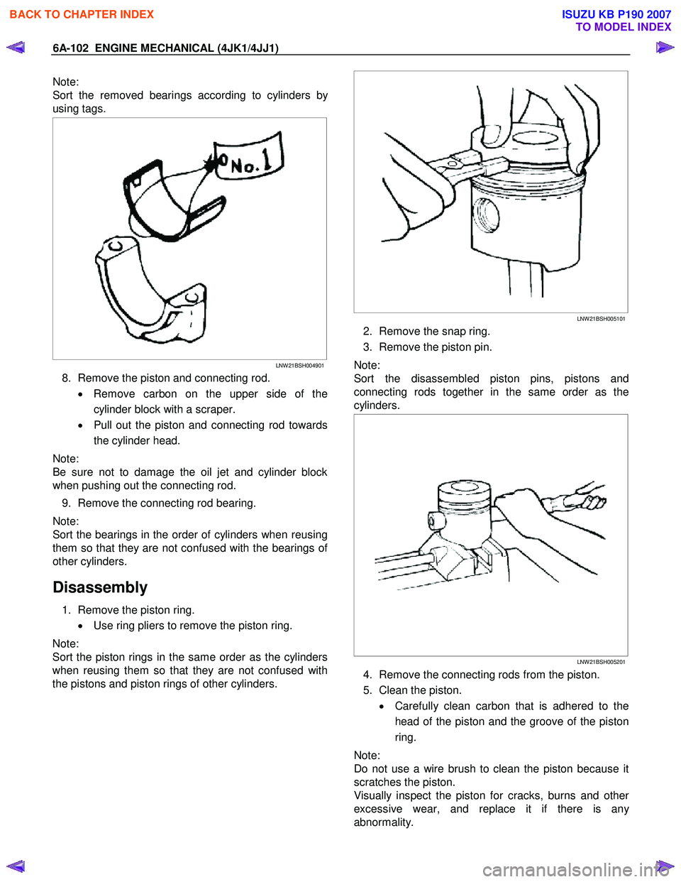
1. Remove the piston ring.
• Use ring pliers to remove the piston ring.
Note:
Sort the piston rings in the same order as the cylinders
when reusing them so that they are not confused with
the pistons and piston rings of other cylinders.
LNW 21BSH005101
2. Remove the snap ring.
3. Remove the piston pin.
Note:
Sort the disassembled piston pins, pistons and
connecting rods together in the same order as the
cylinders.
LNW 21BSH005201
4. Remove the connecting rods from the piston.
5. Clean the piston. • Carefully clean carbon that is adhered to the
head of the piston and the groove of the piston
ring.
Note:
Do not use a wire brush to clean the piston because it
scratches the piston.
Visually inspect the piston for cracks, burns and othe
r
excessive wear, and replace it if there is an
y
abnormality.
BACK TO CHAPTER INDEX
TO MODEL INDEX
ISUZU KB P190 2007
Page 1943 of 6020
6E-326 ENGINE CONTROL SYSTEM (4JK1/4JJ1)
Temperature Sensitivity• An intermittent condition may occur when a component/ connection reaches normal
operating temperature. The condition may occur only when the component/
connection is cold, or only when the component/ connection is hot.
• Freeze Frame, Failure Records or Snapshot Data may help with this type of intermittent conditions, where applicable.
• If the intermittent is related to heat, review the data for a relationship with the following:
- High ambient temperatures.
- Underhood/ engine generated heat.
- Circuit generated heat due to a poor connection, or high electrical load.
- Higher than normal load conditions, towing, etc..
• If the intermittent is related to cold, review the data for the following: - Low ambient temperatures-In extremely low temperatures, ice may form in aconnection or component. Test for water intrusion.
- The condition only occurs on a cold start.
- The condition goes away when the vehicle warms up.
• Information from the customer may help to determine if the trouble follows a pattern that is temperature related.
Electromagnetic Interference (EMI)
and Electrical Noise Some electrical components/ circuits are sensitive to EMI or other types of electrical
noise. Inspect the following conditions:
• A misrouted harness that is too close to high voltage/ high current devices such as injection components, motors, generator etc. These components may induce
electrical noise on a circuit that could interfere with normal circuit operation.
• Electrical system interference caused by a malfunctioning relay, or the ECM driven solenoid or switch. These conditions can cause a sharp electrical surge. Normally,
the problem will occur when the malfunctioning component is operating.
• Improper installation of non-factory or aftermarket add on accessories such as lights, 2-way radios, amplifiers, electric motors, remote starters, alarm systems, cell
phones, etc. These accessories may lead to an emission related failure while in
use, but do not fail when the accessories are not in use.
• Test for any open diodes. Some relays may contain a clamping diode.
• Test the generator for a bad rectifier bridge that may be allowing AC noise into the electrical system.
Incorrect ECM Programming • There are only a few situations where reprogramming a ECM is appropriate:
- An ECM from another vehicle is installed.
- Revised software/ calibration files have been released for this vehicle.
Important: DO NOT reprogram the ECM with the SAME software/ calibration files that
are already present in the ECM. This is not an effective repair for any type of driveability
problem.
• Verify that the ECM contains the correct software/ calibration. If incorrect programming is found, reprogram the ECM with the most current software/
calibration.
Duplicating Failure Conditions • If none of the previous tests are successful, attempt to duplicate and/ or capture the failure conditions.
• Freeze Frame/ Failure Records data, where applicable, contains the conditions that were present when the DTC set.
- Review and record Freeze Frame/ Failure Records data.
- Operate the vehicle under the same conditions that were noted in Freeze Frame/ Failure Records data, as closely as possible. The vehicle must also be
operating within the Conditions for Running the DTC. Refer to Conditions for
Running the DTC in the supporting text of the DTC being diagnosed.
• An alternate method is to drive the vehicle with the DMM connected to a suspected circuit. An abnormal reading on the DMM when the problem occurs, may help you
locate the problem.
Checks
Action
BACK TO CHAPTER INDEX
TO MODEL INDEX
ISUZU KB P190 2007
Page 1978 of 6020
ENGINE CONTROL SYSTEM (4JK1/4JJ1) 6E-361
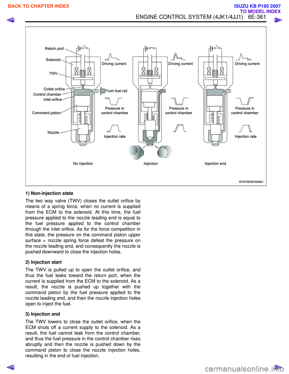
1) Non-injection state
The two way valve (TWV) closes the outlet orifice by
means of a spring force, when no current is supplied
from the ECM to the solenoid. At this time, the fuel
pressure applied to the nozzle leading end is equal to
the fuel pressure applied to the control chamber
through the inlet orifice. As for the force competition in
this state, the pressure on the command piston upper
surface + nozzle spring force defeat the pressure on
the nozzle leading end, and consequently the nozzle is
pushed downward to close the injection holes.
2) Injection start
The TWV is pulled up to open the outlet orifice, and
thus the fuel leaks toward the return port, when the
current is supplied from the ECM to the solenoid. As a
result, the nozzle is pushed up together with the
command piston by the fuel pressure applied to the
nozzle leading end, and then the nozzle injection holes
open to inject the fuel.
3) Injection end
The TWV lowers to close the outlet orifice, when the
ECM shuts off a current supply to the solenoid. As a
result, the fuel cannot leak from the control chamber,
and thus the fuel pressure in the control chamber rises
abruptly and then the nozzle is pushed down by the
command piston to close the nozzle injection holes,
resulting in the end of fuel injection.
RTW76EMF000601
No injection Injection ratePressure in
control chamber Pressure in
control chamber Pressure in
control chamber Driving current
Driving current
Driving current
Injection rate
Injection Injection end
Solenoid
Outlet orifice
Inlet orifice
Command piston
Nozzle From fuel rail
TWV
Return port
Control chamber
BACK TO CHAPTER INDEX
TO MODEL INDEX
ISUZU KB P190 2007
Page 2012 of 6020
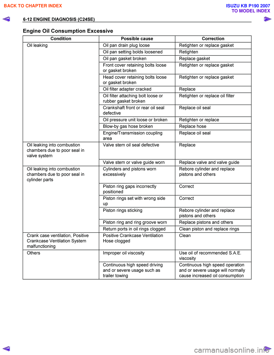
6-12 ENGINE DIAGNOSIS (C24SE)
Engine Oil Consumption Excessive
Condition Possible cause Correction
Oil leaking Oil pan drain plug loose Retighten or replace gasket
Oil pan setting bolds loosened Retighten
Oil pan gasket broken Replace gasket
Front cover retaining bolts loose
or gasket broken Retighten or replace gasket
Head cover retaining bolts loose
or gasket broken Retighten or replace gasket
Oil filter adapter cracked Replace
Oil filter attaching bolt loose or
rubber gasket broken Retighten or replace oil filter
Crankshaft front or rear oil seal
defective Replace oil seal
Oil pressure unit loose or broken Retighten or replace
Blow-by gas hose broken Replace hose
Engine/Transmission coupling
area Replace oil seal
Oil leaking into combustion
chambers due to poor seal in
valve system Valve stem oil seal defective Replace
Valve stem or valve guide worn Replace valve and valve guide
Oil leaking into combustion
chambers due to poor seal in
cylinder parts Cylinders and pistons worn
excessively Rebore cylinder and replace
pistons and others
Piston ring gaps incorrectly
positioned Correct
Piston rings set with wrong side
up Correct
Piston rings sticking Rebore cylinder and replace
pistons and others
Piston ring and ring groove worn Replace pistons and others
Return ports in oil rings clogged Clean piston and replace rings
Crank case ventilation, Positive
Crankcase Ventilation System
malfunctioning Positive Crankcase Ventilation
Hose clogged Clean
Others
Improper oil viscosity Use oil of recommended S.A.E.
viscosity
Continuous high speed driving
and or severe usage such as
trailer towing Continuous high speed operation
and or severe usage will normally
cause increased oil consumption
BACK TO CHAPTER INDEX
TO MODEL INDEX
ISUZU KB P190 2007
Page 2026 of 6020
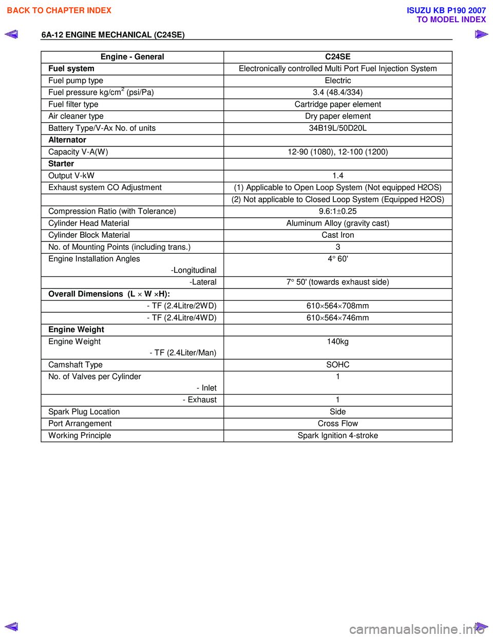
6A-12 ENGINE MECHANICAL (C24SE)
Engine - General C24SE
Fuel system Electronically controlled Multi Port Fuel Injection System
Fuel pump type Electric
Fuel pressure kg/cm2 (psi/Pa) 3.4 (48.4/334)
Fuel filter type Cartridge paper element
Air cleaner type Dry paper element
Battery Type/V-Ax No. of units 34B19L/50D20L
Alternator
Capacity V-A(W ) 12-90 (1080), 12-100 (1200)
Starter
Output V-kW 1.4
Exhaust system CO Adjustment (1) Applicable to Open Loop System (Not equipped H2OS)
(2) Not applicable to Closed Loop System (Equipped H2OS)
Compression Ratio (with Tolerance) 9.6:1±0.25
Cylinder Head Material Aluminum Alloy (gravity cast)
Cylinder Block Material Cast Iron
No. of Mounting Points (including trans.) 3
Engine Installation Angles
-Longitudinal 4
° 60'
-Lateral 7° 50' (towards exhaust side)
Overall Dimensions (L ×
××
×
W ×
××
×
H):
- TF (2.4Litre/2W D)610×564 ×708mm
- TF (2.4Litre/4W D) 610×564 ×746mm
Engine Weight
Engine W eight
- TF (2.4Liter/Man) 140kg
Camshaft Type
SOHC
No. of Valves per Cylinder
- Inlet1
- Exhaust
1
Spark Plug Location Side
Port Arrangement Cross Flow
W orking Principle Spark Ignition 4-stroke
BACK TO CHAPTER INDEX
TO MODEL INDEX
ISUZU KB P190 2007
Page 2055 of 6020
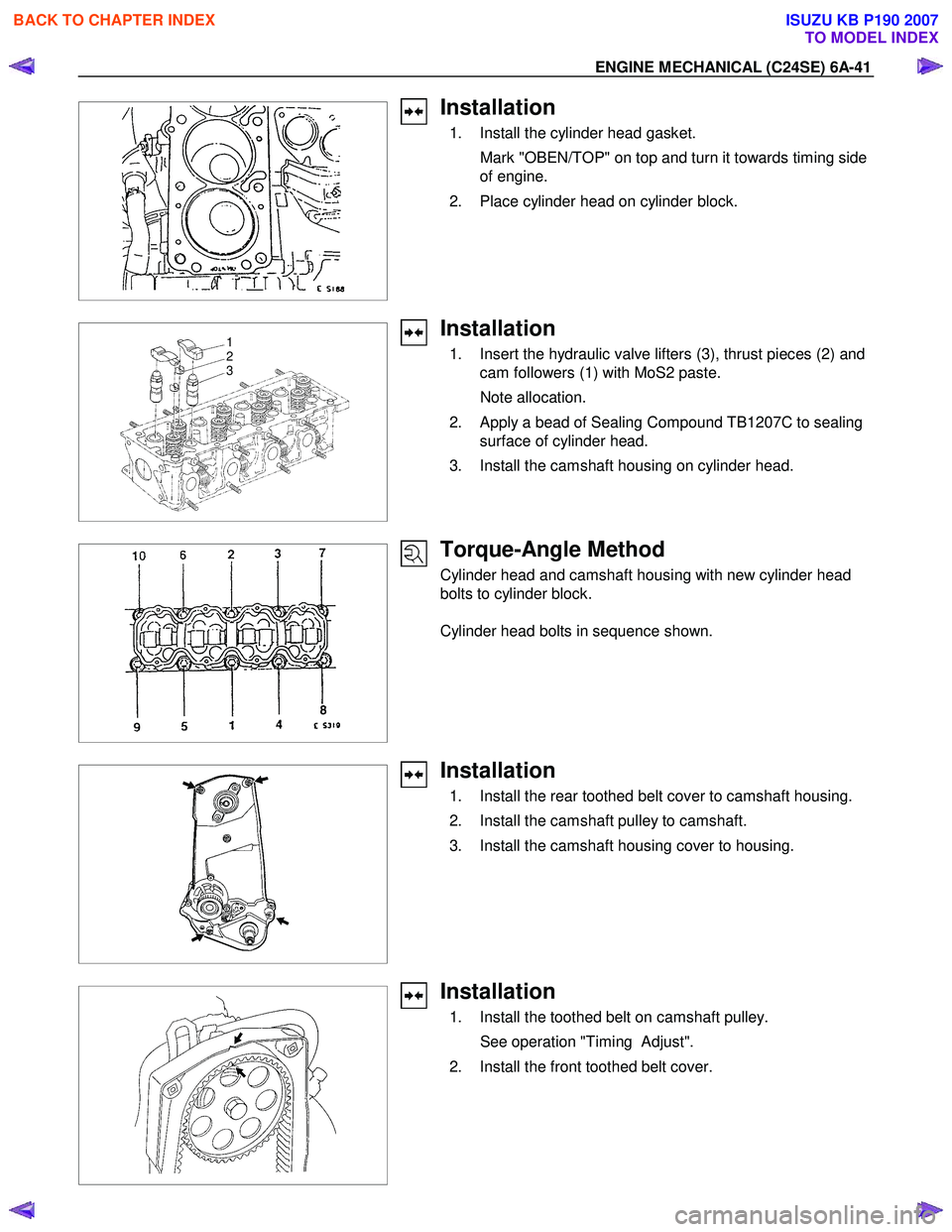
ENGINE MECHANICAL (C24SE) 6A-41
Installation
1. Install the cylinder head gasket.
Mark "OBEN/TOP" on top and turn it towards timing side of engine.
2. Place cylinder head on cylinder block.
1
2
3
Installation
1. Insert the hydraulic valve lifters (3), thrust pieces (2) and
cam followers (1) with MoS2 paste.
Note allocation.
2. Apply a bead of Sealing Compound TB1207C to sealing surface of cylinder head.
3. Install the camshaft housing on cylinder head.
Torque-Angle Method
Cylinder head and camshaft housing with new cylinder head
bolts to cylinder block.
Cylinder head bolts in sequence shown.
Installation
1. Install the rear toothed belt cover to camshaft housing.
2. Install the camshaft pulley to camshaft.
3. Install the camshaft housing cover to housing.
Installation
1. Install the toothed belt on camshaft pulley.
See operation "Timing Adjust".
2. Install the front toothed belt cover.
BACK TO CHAPTER INDEX
TO MODEL INDEX
ISUZU KB P190 2007
Page 2087 of 6020
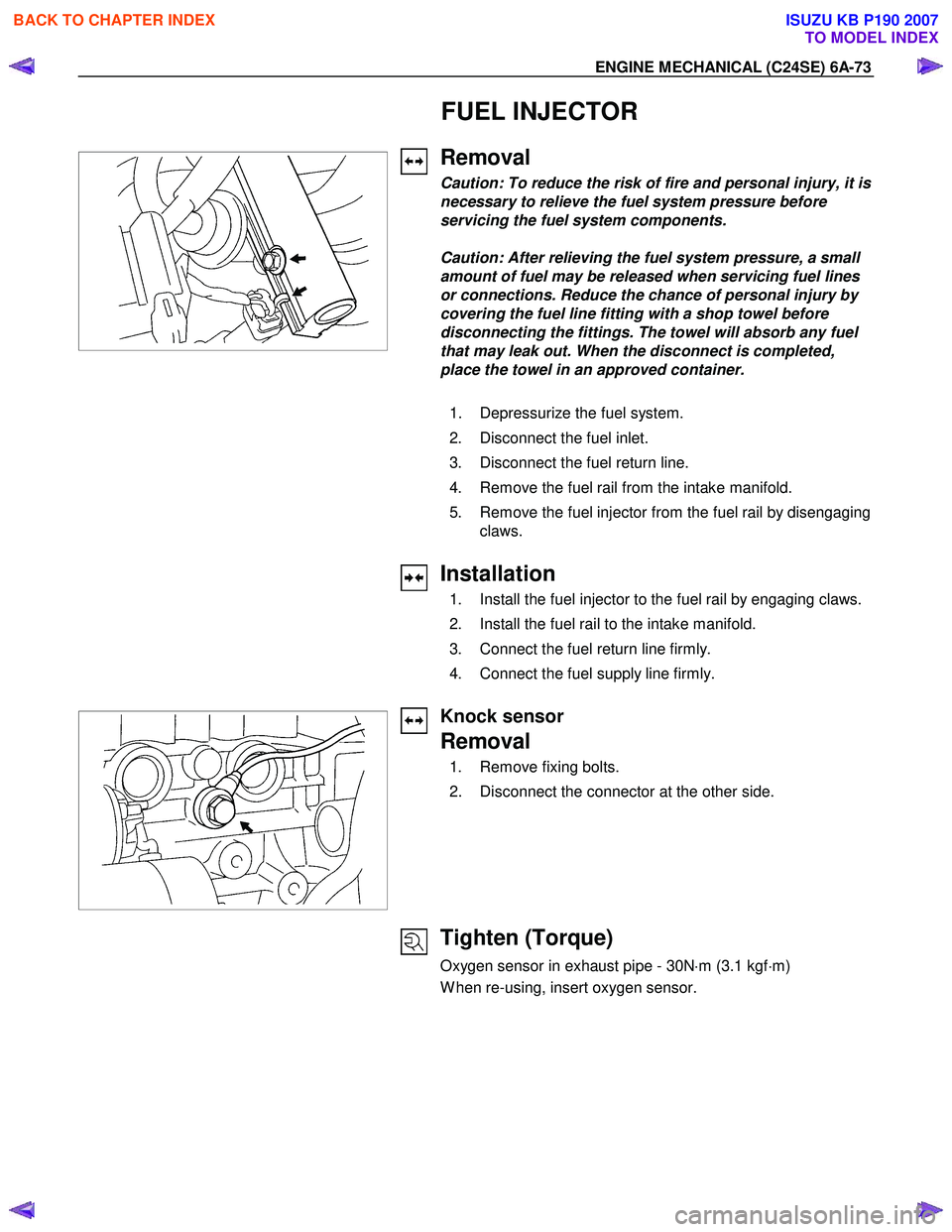
ENGINE MECHANICAL (C24SE) 6A-73
FUEL INJECTOR
Removal
Caution: To reduce the risk of fire and personal injury, it is
necessary to relieve the fuel system pressure before
servicing the fuel system components.
Caution: After relieving the fuel system pressure, a small
amount of fuel may be released when servicing fuel lines
or connections. Reduce the chance of personal injury by
covering the fuel line fitting with a shop towel before
disconnecting the fittings. The towel will absorb any fuel
that may leak out. When the disconnect is completed,
place the towel in an approved container.
1. Depressurize the fuel system.
2. Disconnect the fuel inlet.
3. Disconnect the fuel return line.
4. Remove the fuel rail from the intake manifold.
5. Remove the fuel injector from the fuel rail by disengaging claws.
Installation
1. Install the fuel injector to the fuel rail by engaging claws.
2. Install the fuel rail to the intake manifold.
3. Connect the fuel return line firmly.
4. Connect the fuel supply line firmly.
Knock sensor
Removal
1. Remove fixing bolts.
2. Disconnect the connector at the other side.
Tighten (Torque)
Oxygen sensor in exhaust pipe - 30N ⋅m (3.1 kgf ⋅m)
W hen re-using, insert oxygen sensor.
BACK TO CHAPTER INDEX
TO MODEL INDEX
ISUZU KB P190 2007