Page 2980 of 6020
Engine Mechanical – V6 Page 6A1–203
Page 6A1–203
Left-hand Side
1 Remove the left-hand cylinder head camshaft sprockets, refer to 3.18 Camshaft Sprocket .
NOTE
Tool No. EN-46105–1 was installed as part of the
left-hand cylinder head camshaft sprocket
removal procedure.
2 Remove Tool No. EN-46105–1 (1) from the left-hand camshafts.
NOTE
Tool No. EN-46105 was installed as part of the
left-hand cylinder head camshaft position
actuator removal procedure.
Figure 6A1 – 332
3 Observe the markings (1) on the bearing caps. Each bearing cap is marked in order to identify its location.
The markings have the following meanings:
• The raised feature must always be oriented
toward the centre of the cylinder head.
• An I indicates t he intake camshaft.
• An E indicates the exhaust camshaft.
• The number indicates the journal position from
the front of the engine.
Figure 6A1 – 333
BACK TO CHAPTER INDEX
TO MODEL INDEX
ISUZU KB P190 2007
Page 2986 of 6020

Engine Mechanical – V6 Page 6A1–209
Page 6A1–209
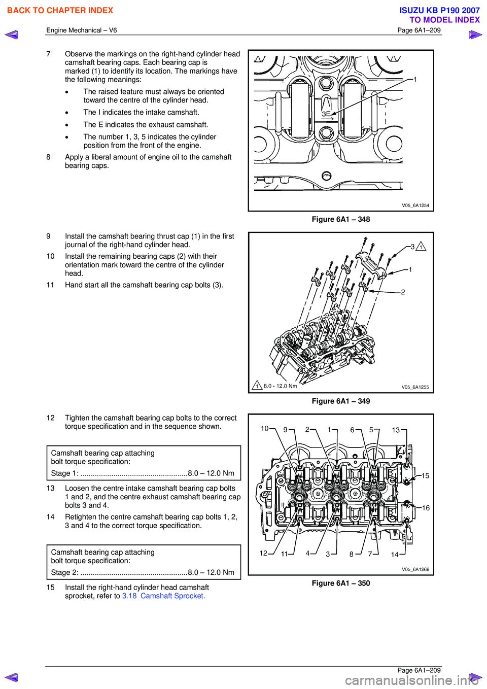
7 Observe the markings on the right-hand cylinder head
camshaft bearing caps. Each bearing cap is
marked (1) to identify its location. The markings have
the following meanings:
• The raised feature must always be oriented
toward the centre of the cylinder head.
• The I indicates the intake camshaft.
• The E indicates the exhaust camshaft.
• The number 1, 3, 5 indicates the cylinder
position from the fr ont of the engine.
8 Apply a liberal amount of engine oil to the camshaft bearing caps.
Figure 6A1 – 348
9 Install the camshaft bearing thrust cap (1) in the first journal of the right-hand cylinder head.
10 Install the remaining bearing caps (2) with their orientation mark toward t he centre of the cylinder
head.
11 Hand start all the camshaft bearing cap bolts (3).
Figure 6A1 – 349
12 Tighten the camshaft bearing cap bolts to the correct torque specification and in the sequence shown.
Camshaft bearing cap attaching
bolt torque specification:
Stage 1: .................................................... 8.0 – 12.0 Nm
13 Loosen the centre intake camshaft bearing cap bolts
1 and 2, and the centre exhaust camshaft bearing cap
bolts 3 and 4.
14 Retighten the centre camsha ft bearing cap bolts 1, 2,
3 and 4 to the correct torque specification.
Camshaft bearing cap attaching
bolt torque specification:
Stage 2: .................................................... 8.0 – 12.0 Nm
15 Install the right-hand cylinder head camshaft
sprocket, refer to 3.18 Camshaft Sprocket .
Figure 6A1 – 350
BACK TO CHAPTER INDEX
TO MODEL INDEX
ISUZU KB P190 2007
Page 2988 of 6020

Engine Mechanical – V6 Page 6A1–211
Page 6A1–211
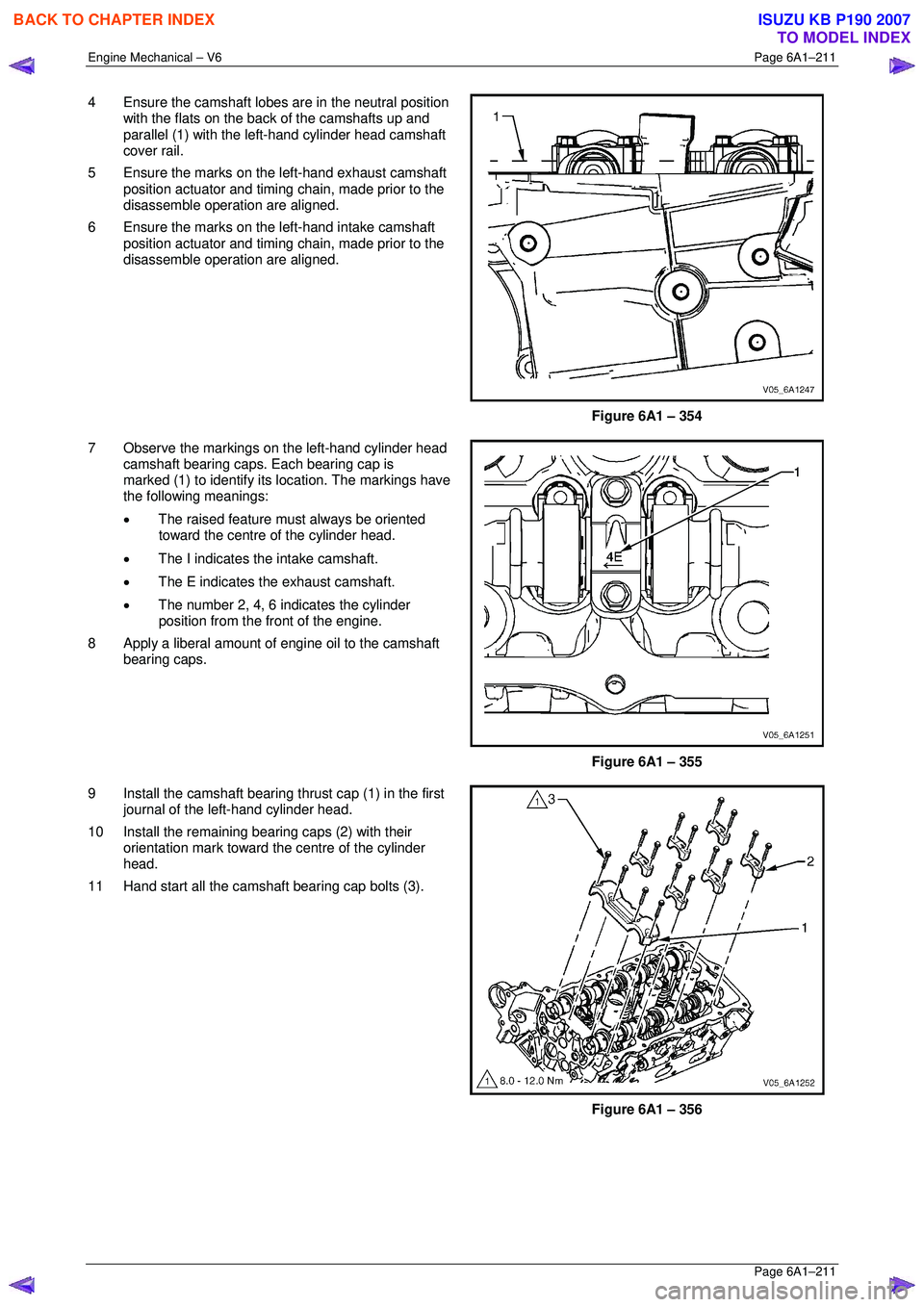
4 Ensure the camshaft lobes are in the neutral position
with the flats on the back of the camshafts up and
parallel (1) with the left-hand cylinder head camshaft
cover rail.
5 Ensure the marks on the left-hand exhaust camshaft position actuator and timing chain, made prior to the
disassemble operation are aligned.
6 Ensure the marks on the left-hand intake camshaft position actuator and timing chain, made prior to the
disassemble operation are aligned.
Figure 6A1 – 354
7 Observe the markings on the left-hand cylinder head camshaft bearing caps. Each bearing cap is
marked (1) to identify its location. The markings have
the following meanings:
• The raised feature must always be oriented
toward the centre of the cylinder head.
• The I indicates the intake camshaft.
• The E indicates the exhaust camshaft.
• The number 2, 4, 6 indicates the cylinder
position from the fr ont of the engine.
8 Apply a liberal amount of engine oil to the camshaft bearing caps.
Figure 6A1 – 355
9 Install the camshaft bearing thrust cap (1) in the first journal of the left-hand cylinder head.
10 Install the remaining bearing caps (2) with their orientation mark toward t he centre of the cylinder
head.
11 Hand start all the camshaft bearing cap bolts (3).
Figure 6A1 – 356
BACK TO CHAPTER INDEX
TO MODEL INDEX
ISUZU KB P190 2007
Page 3008 of 6020

Engine Mechanical – V6 Page 6A1–231
Page 6A1–231
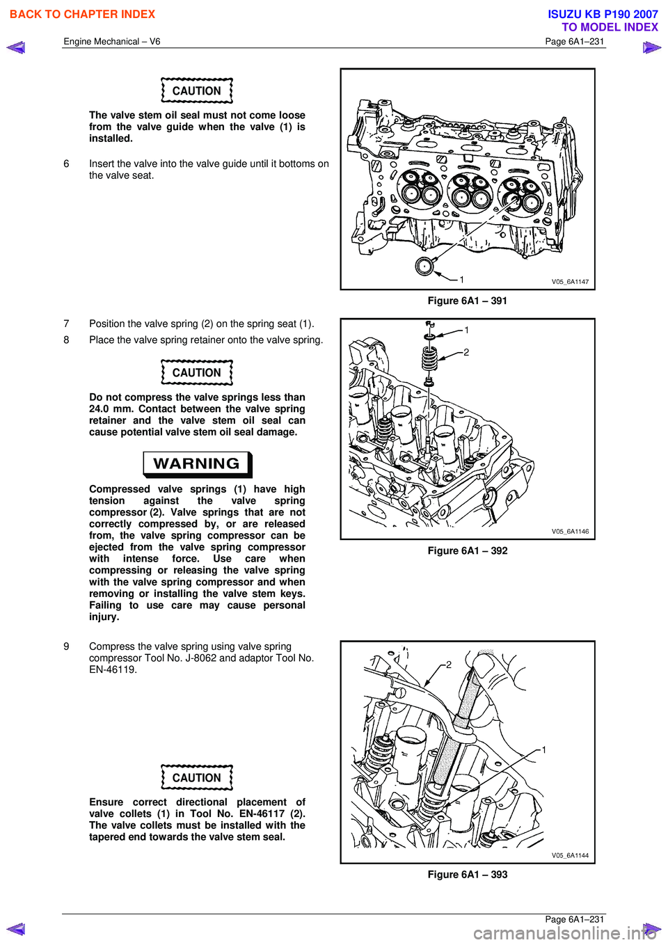
CAUTION
The valve stem oil seal must not come loose
from the valve guide when the valve (1) is
installed.
6 Insert the valve into the valve guide until it bottoms on
the valve seat.
Figure 6A1 – 391
7 Position the valve spring (2) on the spring seat (1).
8 Place the valve spring retainer onto the valve spring.
CAUTION
Do not compress the valve springs less than
24.0 mm. Contact between the valve spring
retainer and the valve stem oil seal can
cause potential valve stem oil seal damage.
Compressed valve springs (1) have high
tension against the valve spring
compressor (2). Valve springs that are not
correctly compressed by, or are released
from, the valve spring compressor can be
ejected from the valve spring compressor
with intense force. Use care when
compressing or releasing the valve spring
with the valve spring compressor and when
removing or installing the valve stem keys.
Failing to use care may cause personal
injury.
Figure 6A1 – 392
9 Compress the valve spring using valve spring compressor Tool No. J-8062 and adaptor Tool No.
EN-46119.
CAUTION
Ensure correct directional placement of
valve collets (1) in Tool No. EN-46117 (2).
The valve collets must be installed with the
tapered end towards the valve stem seal.
Figure 6A1 – 393
BACK TO CHAPTER INDEX
TO MODEL INDEX
ISUZU KB P190 2007
Page 3045 of 6020
Engine Mechanical – V6 Page 6A1–268
Page 6A1–268
NOTE
The cap and rod are a matched set and must be
kept together.
16 Reattach the connecting rod cap (1) to the connecting rod (2) to prevent damage to their mating surfaces.
17 Repeat steps 4 to 16 for the remaining piston and connecting rod assemblies.
Figure 6A1 – 470
Disassemble
CAUTION
A piston ring expander must be used to
remove and install the piston rings. Only
expand the rings far enough to fit over the
piston lands. If the rings are overexpanded,
the top ring will shatter and the others will
distort.
1 Remove the piston rings (2) using a piston ring expander (1). Place each ring in a clean shop towel
for storage.
Figure 6A1 – 471
CAUTION
Do not reuse the piston pin retainers.
2 Remove the piston pin retainers by using the removal access notch (1) in the side of the piston. Discard the
piston pin retainers.
Figure 6A1 – 472
BACK TO CHAPTER INDEX
TO MODEL INDEX
ISUZU KB P190 2007
Page 3051 of 6020
Engine Mechanical – V6 Page 6A1–274
Page 6A1–274
Reassemble
Piston and Piston Pin
CAUTION
The arrow located on top of the piston must
point toward the front of the engine.
NOTE
The connecting rod is non-directional and may
be assembled/reassembled to the piston in
either direction.
1 Lubricate the piston pin (1) bores in the piston (2) and
the connecting rod with clean engine oil.
2 Assemble the piston and piston pin to the connecting rod. Correctly orient the piston when reusing a
marked connecting rod.
3 Align the piston pin bore with the connecting rod pin
bore.
4 Slide the piston pin into the piston and the connecting
rod.
Figure 6A1 – 485
CAUTION
New piston pin retainers must be used.
Never reuse the piston pin retainers.
5 Install new piston pin retainers (1).
6 Ensure the piston pin retainers are fully seated in their grooves.
7 Repeat steps 1 to 6 for the remaining pistons.
Figure 6A1 – 486
BACK TO CHAPTER INDEX
TO MODEL INDEX
ISUZU KB P190 2007
Page 3052 of 6020
Engine Mechanical – V6 Page 6A1–275
Page 6A1–275
Piston Ring
NOTE
The ends of the expander must be facing
toward the top of the piston.
1 Correctly orient the oil control ring expander (1) before installation.
Figure 6A1 – 487
2 Using a piston ring expander, install the oil control
ring assembly using the following procedure:
3 Install the expander ring (3).
4 Install the two oil scraper rings (4). Expand the rings only enough to clear the piston diameter. Over-
expanding the piston rings w ill distort or crack the
rings.
5 Install the second (2) and top (1) piston rings as follows.
Figure 6A1 – 488
6 Using the ring expander (1), install the second piston
ring (2) onto the piston (3). Do not over-expand the
ring. Repeat for the top ring.
Figure 6A1 – 489
BACK TO CHAPTER INDEX
TO MODEL INDEX
ISUZU KB P190 2007
Page 3054 of 6020

Engine Mechanical – V6 Page 6A1–277
Page 6A1–277
Reinstall
Piston Connecting Rod and Connecting Rod Bearing Installation
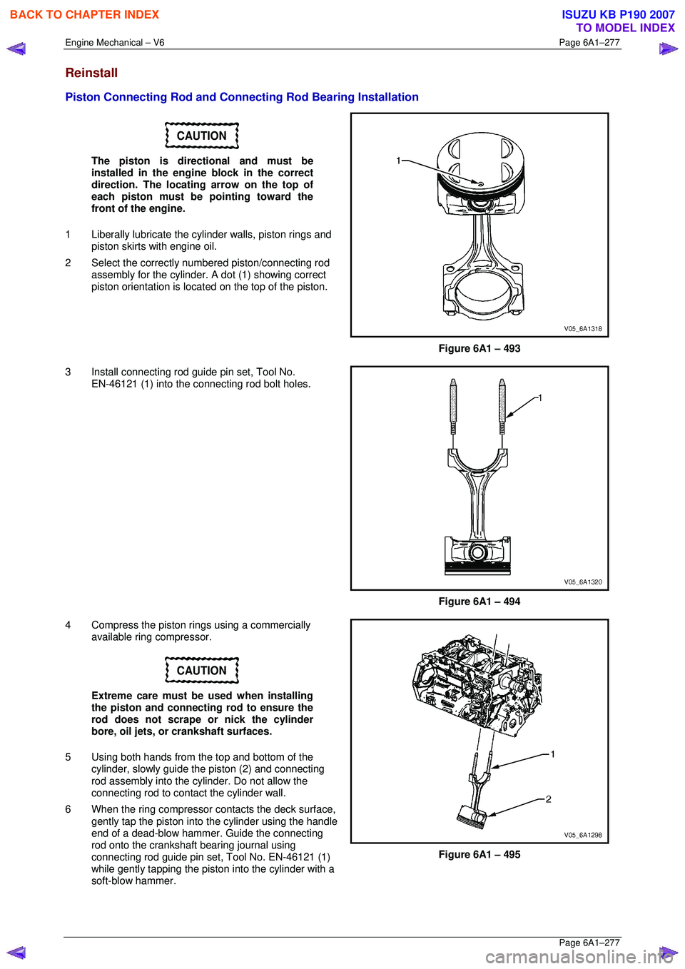
CAUTION
The piston is directional and must be
installed in the engine block in the correct
direction. The locating arrow on the top of
each piston must be pointing toward the
front of the engine.
1 Liberally lubricate the cy linder walls, piston rings and
piston skirts with engine oil.
2 Select the correctly numbered piston/connecting rod
assembly for the cylinder. A dot (1) showing correct
piston orientation is locat ed on the top of the piston.
Figure 6A1 – 493
3 Install connecting rod guide pin set, Tool No. EN-46121 (1) into the connecting rod bolt holes.
Figure 6A1 – 494
4 Compress the piston rings using a commercially available ring compressor.
CAUTION
Extreme care must be used when installing
the piston and connecting rod to ensure the
rod does not scrape or nick the cylinder
bore, oil jets, or crankshaft surfaces.
5 Using both hands from the top and bottom of the cylinder, slowly guide the piston (2) and connecting
rod assembly into the cylinder. Do not allow the
connecting rod to contact the cylinder wall.
6 When the ring compressor c ontacts the deck surface,
gently tap the piston into the cylinder using the handle
end of a dead-blow hammer. Guide the connecting
rod onto the crankshaft bearing journal using
connecting rod guide pin set, Tool No. EN-46121 (1)
while gently tapping the piston into the cylinder with a
soft-blow hammer.
Figure 6A1 – 495
BACK TO CHAPTER INDEX
TO MODEL INDEX
ISUZU KB P190 2007