2007 ISUZU KB P190 tow
[x] Cancel search: towPage 857 of 6020

6A – 52 ENGINE MECHANICAL
RTW 36ASH000801
Idler Gear "A" End Play Measurement
Insert a feeler gauge between the idler gear and the thrust
collar to measure the gap and determine the idler gear
end play.
If the measured value exceeds the specified limit, the
thrust collar must be replaced.
Idler Gear End Play mm (in)
Standard Limit
0.07 (0.0028) 0.2 (0.0079)
4JA1T(L)
040R300009
14. Idle Gear Shaft
15. Crankshaft Timing Gear
4JA1TC/4JH1TC RTW 36ASH001301
16. Injection Pump
1. Remove the injection pump cover (4JA1TC/4JH1TC only).
2. Remove the injection pump bracket.
3. Pull the injection pump along with the injection pump timing gear free toward the rear of the engine.
NOTE:
Plug the injection pump delivery ports with the caps to
prevent the entry of foreign material.
17. Flywheel
Loosen the flywheel bolts in numerical order a little at a
time.
Use the gear stoper to stop the flywheel gear.
Gear stoper: 5-8840-0214-0
18. Crank Case
19. Oil Pump With Oil Pipe
015RY00001
BACK TO CHAPTER INDEX
TO MODEL INDEX
ISUZU KB P190 2007
Page 912 of 6020

ENGINE MECHANICAL 6A – 107
RTW 36ASH002001
11. Piston and Connecting Rod with Upper Bearing
12. Connecting Rod Bearing Cap with Lower Bearing
1. Apply a coat of engine oil to the circumference of each piston ring and piston.
2. Position the piston ring gaps as shown in the illustration.
1. Oil ring
2. 2nd compression ring
3. 1st compression ring
3. Apply a coat of molybdenum disulfide grease to the two
piston skirts.
This will facilitate smooth break-in when the engine is
first started after reassembly.
4. Apply a coat of engine oil to the upper bearing surfaces.
5. Apply a coat of engine oil to the cylinder wall.
6. Position the piston head front mark so that it is facing
the front of the engine.
7. Use the piston ring compressor to compress the piston rings.
Piston Ring Compressor: 5-8840-9018-0
8. Use a hammer grip to push the piston in until the connecting rod makes contact with the crankpin.
At the same time, rotate the crankshaft until the
crankpin is at BDC.
9. Align the bearing cap cylinder number marks and the connecting rod cylinder number marks.
The cylinder number marks must be turned toward the
exhaust manifold.
015LX096
015R100007 015R100006
BACK TO CHAPTER INDEX
TO MODEL INDEX
ISUZU KB P190 2007
Page 1009 of 6020
6D – 8 ENGINE ELECTRICAL
033RY00009
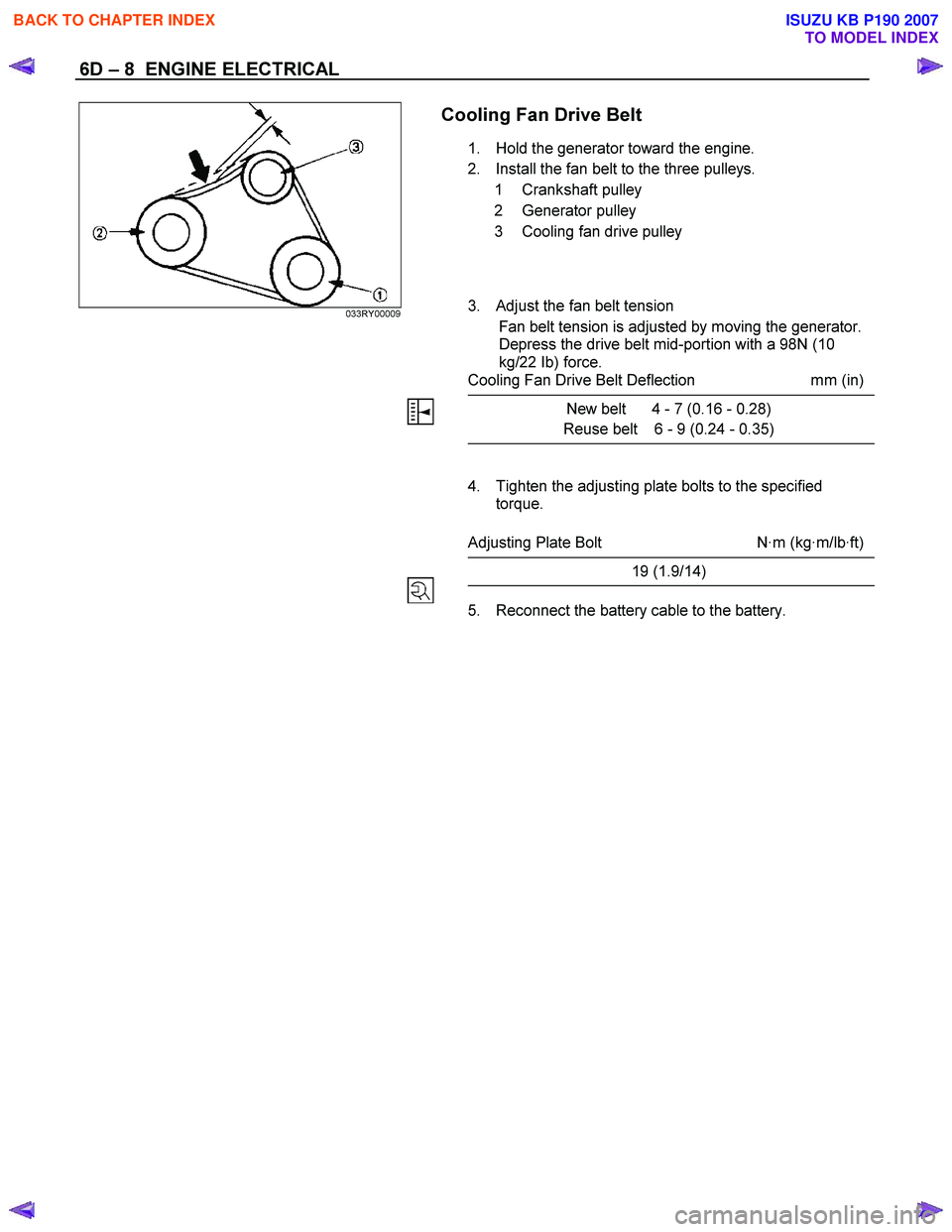
Cooling Fan Drive Belt
1. Hold the generator toward the engine.
2. Install the fan belt to the three pulleys. 1 Crankshaft pulley
2 Generator pulley
3 Cooling fan drive pulley
3. Adjust the fan belt tension
Fan belt tension is adjusted by moving the generator.
Depress the drive belt mid-portion with a 98N (10
kg/22 Ib) force.
Cooling Fan Drive Belt Deflection mm (in)
New belt 4 - 7 (0.16 - 0.28)
Reuse belt 6 - 9 (0.24 - 0.35)
4. Tighten the adjusting plate bolts to the specified torque.
Adjusting Plate Bolt N·m (kg·m/lb·ft)
19 (1.9/14)
5. Reconnect the battery cable to the battery.
BACK TO CHAPTER INDEX
TO MODEL INDEX
ISUZU KB P190 2007
Page 1289 of 6020
Engine Control System (4JH1) 6E-255
Symptoms – Engine Controls
Symptoms – Engine Controls
Important Preliminary Inspections Before Starting
Perform Diagnostic System Check – Engine Controls
before using the symptom tables, and verify that all o
f
the following are true:
• The engine control module (ECM) and malfunction
indicator lamp (MIL) are operating correctly.
• There are no diagnostic trouble codes (DTCs)
stored, or a DTC exists but without the MIL.
• The scan tool data is within the normal operating
range. Refer to scan tool Data List in this section.
• Verify the customer concern and locate the correct
symptom in the table of contents. Inspect the items
indicated under that symptom.
Visual and Physical Inspection
Several of the symptom procedures ask for careful
visual and physical inspection. This step is extremel
y
important. The visual and physical inspection can lead
to correcting a problem without further inspections, and
can save valuable time. Ensure that:
• The ECM grounds are clean, tight, and in thei
r
proper location.
• The vacuum hoses are not split or kinked, and
properly connected. Inspect thoroughly for an
y
type of leak or restriction.
• The mass air flow (MAF) sensor is properl
y
installed. The arrows on the plastic portion of the
sensor must point toward the engine.
• The air intake ducts are not collapsed or damaged.
• There are no leaks at the MAF sensor, an
y
connections or intake manifold sealing surfaces.
• The engine harness wiring and terminals are
properly connected and are not pinched or cut.
Intermittent
Important:
Inspect for improper installation of electrical
components if an intermittent condition exists. Inspect
for aftermarket add-on electrical equipment devices,
lights, and cellular phones. Verify that no aftermarket
equipment is connected to the keyword 2000 serial data
circuit. If you cannot locate an intermittent condition, a
cellular phone communication signal may cause the
condition.
Important:
The problem may or may not turn ON the MIL or store a
DTC.
Faulty electrical connections or wiring cause most
intermittent problems. Perform a careful visual and
physical inspection of the suspect connectors for the
following conditions:
• Improperly mated connector halves
• Terminals that are not seated
• Terminals that are damaged or improperly formed
Reform or replace connector terminals in the problem
circuit in order to ensure proper contact tension.
Remove the terminal from the connector body in orde
r
to inspect for poor terminal wire connection.
Road test the vehicle with the DMM connected to the
suspected circuit. An abnormal reading that occurs
when the malfunction occurs is a good indication that
there is a malfunction in the circuit being monitored.
Use the scan tool in order to help detect intermittent
conditions. Useful features of the scan tool include the
following:
• Trigger the Snapshot feature in order to capture
and store engine parameters when the malfunction
occurs. Review this stored information in order to
see the specific running conditions that caused the
malfunction.
• Use the Plot Function on the scan tool in order to
plot selected data parameters. Review this stored
information to aid in locating an intermittent
problem. Refer to the scan tool Users Guide fo
r
more information.
Important:
If the intermittent condition exists as a start and then
stall, test for DTCs relating to the vehicle theft deterrent
system. Test for improper installation of electrical
options such as lights, cellular phones, etc.
Any of the following may cause an intermittent MIL with
no stored DTC:
• The ECM grounds are loose or dirty. Refer to
Engine Controls Schematics.
• The MIL circuit intermittently shorted to ground.
• Electrical system interference caused by a
malfunctioning relay, ECM driven solenoid, o
r
switch. The electrical component can cause a
sharp electrical surge. Normally, the problem will
occur when the malfunctioning component is
operating.
• There is an open diode across the A/C
compressor clutch or any other open diodes.
BACK TO CHAPTER INDEX
TO MODEL INDEX
ISUZU KB P190 2007
Page 1291 of 6020

Engine Control System (4JH1) 6E-257
Checks Action
Electrical Connections or W iring Poor electrical connections, terminal tension or wiring problems cause most intermittent. To perform the following inspections:
• Inspect for poor mating of the connector halves, or terminals improperly seated in the
connector body.
• Inspect for improperly formed or damaged terminals. Test for poor terminal tension.
• Inspect for poor terminal to wire connections including terminals crimped over
insulation. This requires removing the terminal from the connector body.
• Inspect for corrosion/water intrusion. Pierced or damaged insulation can allow
moisture to enter the wiring. The conductor can corrode inside the insulation, with
little visible evidence. Look for swollen and stiff sections of wire in the suspect
circuits.
• Inspect for wires that are broken inside the insulation.
• Inspect the harness for pinched, cut or rubbed through wiring.
• Ensure that the wiring does not come in contact with hot exhaust components.
Control Module Power and Grounds
Component Power and Grounds Poor power or ground connections can cause widely varying symptoms.
• Test all control module power supply circuits. Many vehicles have multiple circuits
supplying power to the control module. Other components in the system may have
separate power supply circuits that may also need to be tested. Inspect connections
at the module/component connectors, fuses, and any intermediate connections
between the power source and the module/component. A test lamp or a DMM may
indicate that voltage is present, but neither tests the ability of the circuit to carry
sufficient current. Ensure that the circuit can carry the current necessary to operate
the component.
• Test all control module ground and system ground circuits. The control module may
have multiple ground circuits. Other components in the system may have separate
grounds that may also need to be tested. Inspect grounds for clean and tight
connections at the grounding point. Inspect the connections at the component and in
splice packs, where applicable. Ensure that the circuit can carry the current
necessary to operate the component.
Temperature Sensitivity • An intermittent condition may occur when a component/connection reaches normal
operating temperature. The condition may occur only when the
component/connection is cold, or only when the component/connection is hot.
• If the intermittent is related to heat, review the data for a relationship with the
following: - High ambient temperatures
- Under hood/engine generated heat
- Circuit generated heat due to a poor connection, or high electrical load
- Higher than normal load conditions, towing, etc.
• If the intermittent is related to cold, review the data for the following:
- Low ambient temperatures–In extremely low temperatures, ice may form in a connection or component. Test for water intrusion.
- The condition only occurs on a cold start.
- The condition goes away when the vehicle warms up.
• Information from the customer may help to determine if the trouble follows a pattern
that is temperature related.
BACK TO CHAPTER INDEX
TO MODEL INDEX
ISUZU KB P190 2007
Page 1314 of 6020
6E-280 Engine Control System (4JH1)
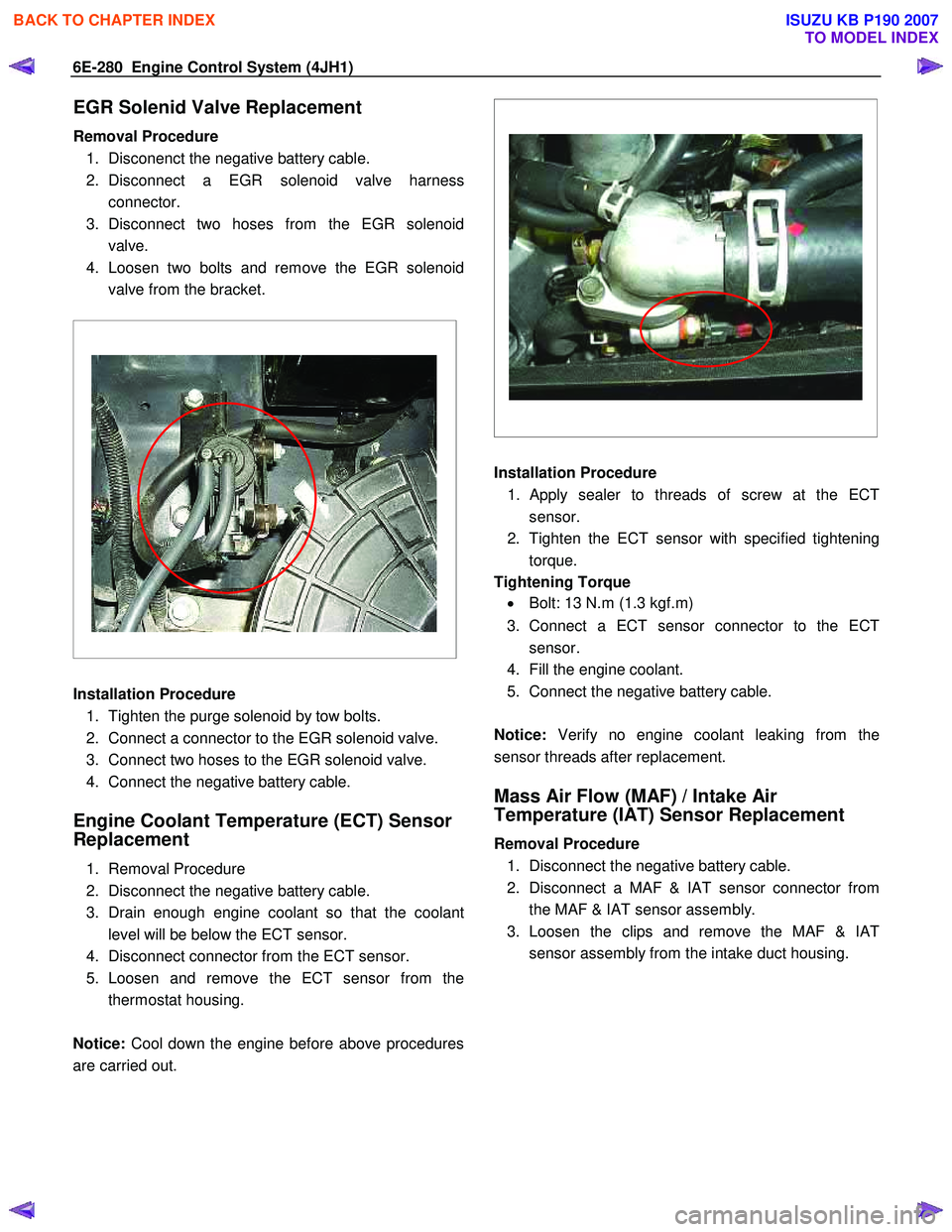
EGR Solenid Valve Replacement
Removal Procedure 1. Disconenct the negative battery cable.
2. Disconnect a EGR solenoid valve harness connector.
3. Disconnect two hoses from the EGR solenoid valve.
4. Loosen two bolts and remove the EGR solenoid valve from the bracket.
Installation Procedure
1. Tighten the purge solenoid by tow bolts.
2. Connect a connector to the EGR solenoid valve.
3. Connect two hoses to the EGR solenoid valve.
4. Connect the negative battery cable.
Engine Coolant Temperature (ECT) Sensor
Replacement
1. Removal Procedure
2. Disconnect the negative battery cable.
3. Drain enough engine coolant so that the coolant level will be below the ECT sensor.
4. Disconnect connector from the ECT sensor.
5. Loosen and remove the ECT sensor from the thermostat housing.
Notice: Cool down the engine before above procedures
are carried out.
Installation Procedure
1.
Apply sealer to threads of screw at the ECT
sensor.
2. Tighten the ECT sensor with specified tightening torque.
Tightening Torque • Bolt: 13 N.m (1.3 kgf.m)
3. Connect a ECT sensor connector to the ECT sensor.
4. Fill the engine coolant.
5. Connect the negative battery cable.
Notice: Verify no engine coolant leaking from the
sensor threads after replacement.
Mass Air Flow (MAF) / Intake Air
Temperature (IAT) Sensor Replacement
Removal Procedure
1. Disconnect the negative battery cable.
2. Disconnect a MAF & IAT sensor connector from the MAF & IAT sensor assembly.
3. Loosen the clips and remove the MAF & IAT sensor assembly from the intake duct housing.
BACK TO CHAPTER INDEX
TO MODEL INDEX
ISUZU KB P190 2007
Page 1327 of 6020
Engine Control System (4JH1) 6E-293
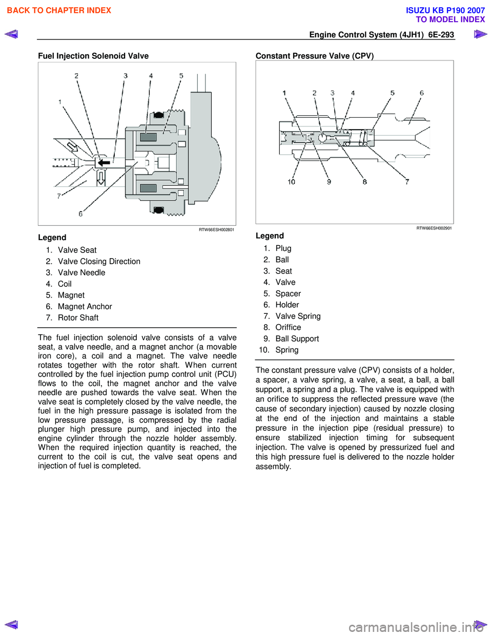
Fuel Injection Solenoid Valve
RTW 66ESH002801
Legend
1. Valve Seat
2. Valve Closing Direction
3. Valve Needle
4. Coil
5. Magnet
6. Magnet Anchor
7. Rotor Shaft
The fuel injection solenoid valve consists of a valve
seat, a valve needle, and a magnet anchor (a movable
iron core), a coil and a magnet. The valve needle
rotates together with the rotor shaft. W hen current
controlled by the fuel injection pump control unit (PCU)
flows to the coil, the magnet anchor and the valve
needle are pushed towards the valve seat. W hen the
valve seat is completely closed by the valve needle, the
fuel in the high pressure passage is isolated from the
low pressure passage, is compressed by the radial
plunger high pressure pump, and injected into the
engine cylinder through the nozzle holder assembly.
W hen the required injection quantity is reached, the
current to the coil is cut, the valve seat opens and
injection of fuel is completed.
Constant Pressure Valve (CPV)
RTW 66ESH002901
Legend
1. Plug
2. Ball
3. Seat
4. Valve
5. Spacer
6. Holder
7. Valve Spring
8. Oriffice
9. Ball Support
10. Spring
The constant pressure valve (CPV) consists of a holder,
a spacer, a valve spring, a valve, a seat, a ball, a ball
support, a spring and a plug. The valve is equipped with
an orifice to suppress the reflected pressure wave (the
cause of secondary injection) caused by nozzle closing
at the end of the injection and maintains a stable
pressure in the injection pipe (residual pressure) to
ensure stabilized injection timing for subsequent
injection. The valve is opened by pressurized fuel and
this high pressure fuel is delivered to the nozzle holde
r
assembly.
BACK TO CHAPTER INDEX
TO MODEL INDEX
ISUZU KB P190 2007
Page 1353 of 6020
6F – 20 EXHAUST SYSTEM
IHI SERVICE NETWORK
For inquiries relating to turbochargers, please contact your ISUZU distributor or the nearest IHI Turbocharger
Service Facility.
HEADQUART ERS
ISHIKAWAJIMA HARIMA HEAVY INDUSTRIES CO., LTD.(IHI)
General Machinery Division
Tokyo Chuo Building 1-6-2 Marunouchi Chiyoda-ku
Tokyo 100-0005 JAPAN
TEL: 81-(3)-3286-2405 to 2407 (3 lines)
FAX: 81-(3)-3286-2430
CHINA
IHI BEIJING OFFICE
Room 705, China W orld Trade Center, No. 1 Jian Guo Men W ai Avenue
Beijing, People’s Republic of CHINA
TEL: 86-(1)-505-4997, 0408
FAX: 86-(1)-505-4350
TLX: 210343 IHIPK CN
TAIWAN
IHI TAIPEI OFFICE
Room 1202, Chia Hsin Building, No. 96 Chung Shan
North Road, Section 2, Taipei, TAIW AN
TEL: 886-(2)-542-5520, 5521, 5523
FAX: 886-(2)-542-4362
TLX: 11320 IHICO
THAILAND
IHI BANGKOK OFFICE
8th Floor, Thaniya Building, 62 Silom Road, Bangkok, THAILAND
TEL: 66-(2)-236-3490, 7356, 9099
FAX: 66-(2)-236-7340
TLX: 82375 IHICO TH
MALAYSIA
IHI KUALA LUMPUR OFFICE
Letter Box No. 52, 22nd Floor, UBN Tower,
10 Jin. P. Ramlee 50250 Kuala Lumpur, MALAYSIA
TEL: 60-(3)-232-1255, 1271
FAX: 60-(3)-232-1418
TLX: IHI KLMA 20257
INDONESIA
IHI JAKARTA OFFICE
9th Floor, Skyline Building JI. M. H. Thamrin, No. 9, Jakarta, INDONESIA
TEL: 62-(21)-32-2147, 390-2211
FAX: 62-(21)-32-3273
TLX: 44175 IHIJKT
BACK TO CHAPTER INDEX
TO MODEL INDEX
ISUZU KB P190 2007