Page 4743 of 6020
7B1-24 Manual Transmission (MUX)
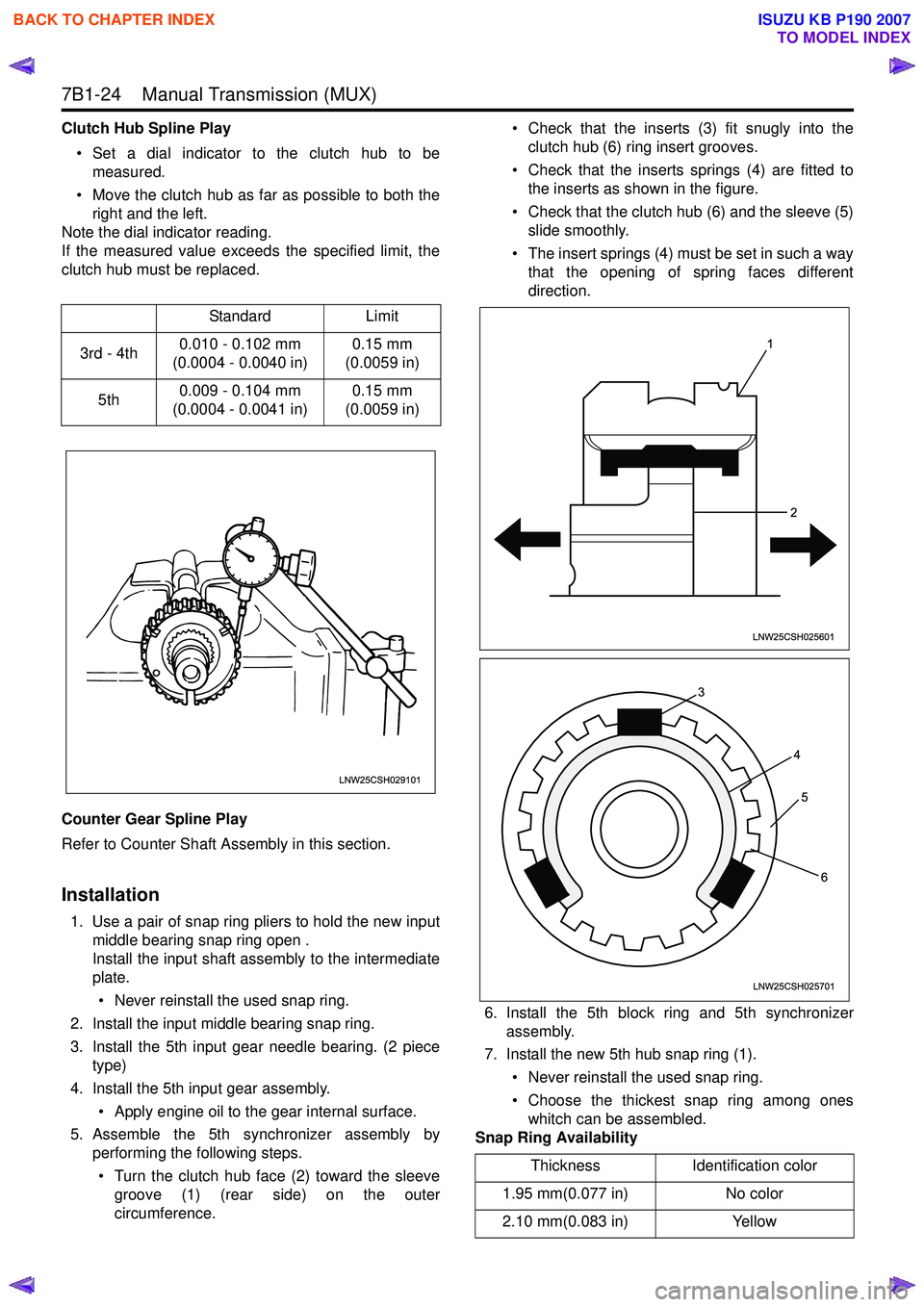
Clutch Hub Spline Play• Set a dial indicator to the clutch hub to be measured.
• Move the clutch hub as far as possible to both the right and the left.
Note the dial indicator reading.
If the measured value exceeds the specified limit, the
clutch hub must be replaced.
Counter Gear Spline Play
Refer to Counter Shaft Assembly in this section.
Installation
1. Use a pair of snap ring pliers to hold the new input middle bearing snap ring open .
Install the input shaft assembly to the intermediate
plate.
• Never reinstall the used snap ring.
2. Install the input middle bearing snap ring.
3. Install the 5th input gear needle bearing. (2 piece type)
4. Install the 5th input gear assembly. • Apply engine oil to the gear internal surface.
5. Assemble the 5th synchronizer assembly by performing the following steps.
• Turn the clutch hub face (2) toward the sleeve groove (1) (rear side) on the outer
circumference. • Check that the inserts (3) fit snugly into the
clutch hub (6) ring insert grooves.
• Check that the inserts springs (4) are fitted to the inserts as shown in the figure.
• Check that the clutch hub (6) and the sleeve (5) slide smoothly.
• The insert springs (4) must be set in such a way that the opening of spring faces different
direction.
6. Install the 5th block ring and 5th synchronizer assembly.
7. Install the new 5th hub snap ring (1).
• Never reinstall the used snap ring.
• Choose the thickest snap ring among ones whitch can be assembled.
Snap Ring Availability
Standard
Limit
3rd - 4th 0.010 - 0.102 mm
(0.0004 - 0.0040 in) 0.15 mm
(0.0059 in)
5th 0.009 - 0.104 mm
(0.0004 - 0.0041 in) 0.15 mm
(0.0059 in)
LNW25CSH029101
Thickness Identification color
1.95 mm(0.077 in) No color
2.10 mm(0.083 in) Yellow
1
2
LNW25CSH025601
3 45
6
LNW25CSH025701
BACK TO CHAPTER INDEX
TO MODEL INDEX
ISUZU KB P190 2007
Page 4744 of 6020
Manual Transmission (MUX) 7B1-25
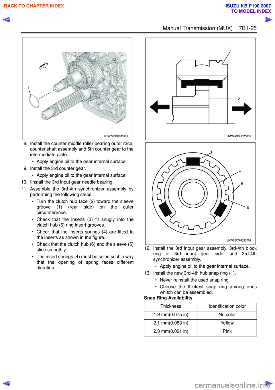
8. Install the counter middle roller bearing outer race,counter shaft assembly and 5th counter gear to the
intermediate plate.
• Apply engine oil to the gear internal surface.
9. Install the 3rd counter gear. • Apply engine oil to the gear internal surface.
10. Iinstall the 3rd input gear needle bearing.
11. Assemble the 3rd-4th synchronizer assembly by performing the following steps.
• Turn the clutch hub face (2) toward the sleeve groove (1) (rear side) on the outer
circumference.
• Check that the inserts (3) fit snugly into the clutch hub (6) ring insert grooves.
• Check that the inserts springs (4) are fitted to the inserts as shown in the figure.
• Check that the clutch hub (6) and the sleeve (5) slide smoothly.
• The insert springs (4) must be set in such a way that the opening of spring faces different
direction. 12. Install the 3rd input gear assembly, 3rd-4th block
ring of 3rd input gear side, and 3rd-4th
synchronizer assembly.
• Apply engine oil to the gear internal surface.
13. Install the new 3rd-4th hub snap ring (1).
• Never reinstall the used snap ring.
• Choose the thickest snap ring among ones whitch can be assembled.
Snap Ring Availability
RTW77BSH005101
1
Thickness Identification color
1.9 mm(0.075 in) No color
2.1 mm(0.083 in) Yellow
2.3 mm(0.091 in) Pink
1
2
LNW25CSH025601
3 45
6
LNW25CSH025701
BACK TO CHAPTER INDEX
TO MODEL INDEX
ISUZU KB P190 2007
Page 4877 of 6020
TRANSFER CONTROL SYSTEM 7D1-3
General Description
RTW 77DLF000501
Transfer Position and Drive Mode
Three drive modes can be selected through operation of 4W D switch.
Transfer Position 4WD SWITCH Mode Drive mode
2H RW D Rear wheel drive
HIGH
4H 4W D (HIGH) High-speed mechanical
lock-up four wheel drive
LOW 4L 4W D (LOW ) Low-speed mechanical
lock-up four wheel drive
NEUTRAL 2H & 4L (10 Sec) NEUTRAL Towed by other vehicle
BACK TO CHAPTER INDEX
TO MODEL INDEX
ISUZU KB P190 2007
Page 4943 of 6020
ELECTRICAL-BODY AND CHASSIS 8A-5
NOTES FOR WORKING ON ELECTRICAL ITEMS
Battery
BATTERY CABLE
Disconnecting the Battery Cable
5. All switches should be “OFF” position.
5. Disconnect the battery ground cable.
5. Disconnect the battery positive cable.
CAUTION:
It is important that the battery ground cable be
disconnected first.
Disconnecting the battery positive cable first can result in
a short circuit.
Connecting the Battery Cable
Follow the disconnecting procedure in the reverse order to
connect the battery cables.
CAUTION:
Clean the battery terminal and apply light coat of grease to
prevent terminal corrosion.
CONNECTOR HANDLING
Disconnecting the Connectors
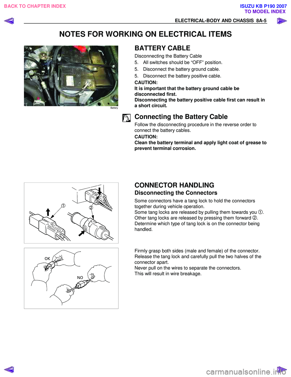
Some connectors have a tang lock to hold the connectors
together during vehicle operation.
Some tang locks are released by pulling them towards you
1.
Other tang locks are released by pressing them forward
2.
Determine which type of tang lock is on the connector being
handled.
Firmly grasp both sides (male and female) of the connector.
Release the tang lock and carefully pull the two halves of the
connector apart.
Never pull on the wires to separate the connectors.
This will result in wire breakage.
BACK TO CHAPTER INDEX TO MODEL INDEXISUZU KB P190 2007
Page 4945 of 6020
ELECTRICAL-BODY AND CHASSIS 8A-7
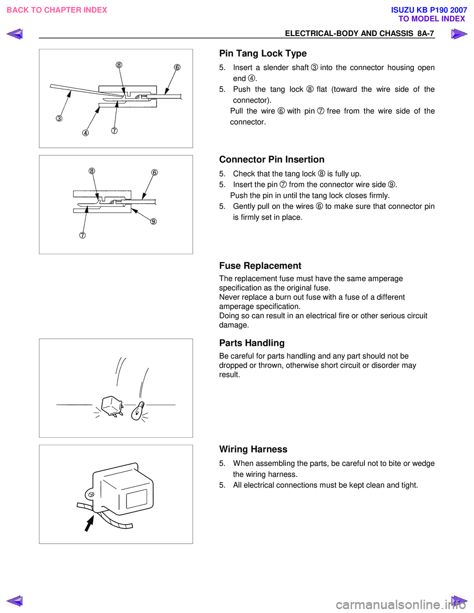
Pin Tang Lock Type
5. Insert a slender shaft 3into the connector housing open
end
4.
5. Push the tang lock
8flat (toward the wire side of the
connector).
Pull the wire
6 with pin 7free from the wire side of the
connector.
Connector Pin Insertion
5. Check that the tang lock 8 is fully up.
5. Insert the pin
7 from the connector wire side 9.
Push the pin in until the tang lock closes firmly.
5. Gently pull on the wires
6to make sure that connector pin
is firmly set in place.
Fuse Replacement
The replacement fuse must have the same amperage
specification as the original fuse.
Never replace a burn out fuse with a fuse of a different
amperage specification.
Doing so can result in an electrical fire or other serious circuit
damage.
Parts Handling
Be careful for parts handling and any part should not be
dropped or thrown, otherwise short circuit or disorder may
result.
Wiring Harness
5. W hen assembling the parts, be careful not to bite or wedge
the wiring harness.
5. All electrical connections must be kept clean and tight.
BACK TO CHAPTER INDEX TO MODEL INDEXISUZU KB P190 2007
Page 4958 of 6020
8A-20 ELECTRICAL-BODY AND CHASSIS
Caution:
Never push or tow the vehicle in an attempt to start it.
Extensive damage to the emission system and other
vehicle parts will result.
(Only catalytic converter vehicle)
Treat both the discharged battery and the booster battery
with great care when using jumper cables.
Carefully follow the procedure outlined below.
Always be aware of the dangers of sparking.
Failure to follow the following procedure can result in:
a. Serious personal injury, specially to your eyes.
b. Extensive property damage from a battery explosion, battery acid discharge, or electrical file.
c. Extensive damage to the electronic components o
f
both vehicles.
Do not use a 24 volt booster battery.
Serious damage to the vehicle's electrical system and
electronic components will result.
Jump Starting Procedure
1. Set the parking brake on both vehicles.
2. If one or both vehicles is equipped with a manual transmission, place the gear shift in the "NEUTRAL"
position.
3. Turn off the ignition on both vehicles.
4. Turn off all vehicle lights and accessories.
5 Be sure that the two vehicles are not touching.
Attach the end of one jumper cable to the booster battery
positive terminal.
6
Attach the other end of the same cable to the discharged
battery positive terminal.
7. Once again, check that the booster battery has a 12 volt rating.
8.
Attach one end of the remaining booster cable to the
booster battery negative terminal.
9.
Attach the other end of the booster cable to a solid ground
(such as the air conditioner compressor mounting bracket
or the alternator mounting bracket) in the engine room o
f
the vehicle with the discharged battery.
10.Be sure that the ground connection is at least 500 mm (20 in) from the discharged battery.
BACK TO CHAPTER INDEX TO MODEL INDEXISUZU KB P190 2007
Page 5115 of 6020
ELECTRICAL-BODY AND CHASSIS 8A-177
HEADLIGHT ADJUSTMENT
Preparation
Place the vehicle with 1 person in driver seat on a level surface
and check to see if the inflation pressure of the tires is correct,
the lenses are clean, the battery is sufficiently charged, and
adjust to place vehicle by using the screen.
1. Set a vertical screen on a level surface.
2. Toward the screen
1from the bulb center mark of the
headlight, extend parallel lines to the floor. Mark point
A
and B on the screen at the intersection of parallel line and
the screen.
3. Draw vertical lines through point
A and B on the screen.
4. Keep the vehicle 2 1m apart from the screen 1.
5. Draw a horizontal line through point
A and Bon the screen
1.
6. Turn the headlight low beam on.
7. Adjust the CUTLINE 11.6 mm below the horizontal line
H.
8. Adjust the BENDING POINT to the vertical line
V.
NOTE:
Always adjust vertical adjustment first.
BACK TO CHAPTER INDEX TO MODEL INDEXISUZU KB P190 2007
Page 5125 of 6020
ELECTRICAL-BODY AND CHASSIS 8A-187
RTW 780SH000601
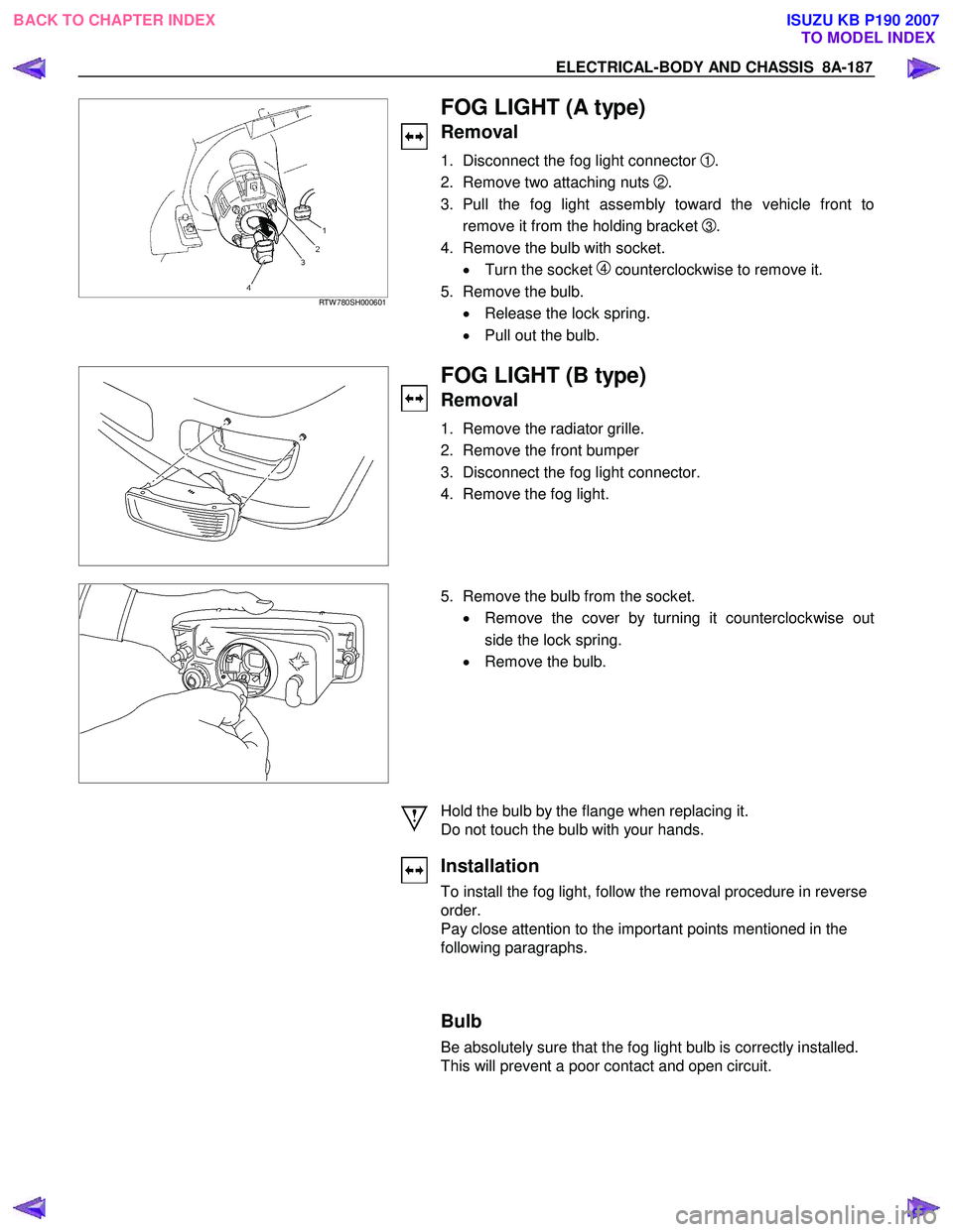
FOG LIGHT (A type)
Removal
1. Disconnect the fog light connector 1 .
2. Remove two attaching nuts
2.
3. Pull the fog light assembly toward the vehicle front to remove it from the holding bracket
3 .
4. Remove the bulb with socket. • Turn the socket
4 counterclockwise to remove it.
5. Remove the bulb. • Release the lock spring.
• Pull out the bulb.
FOG LIGHT (B type)
Removal
1. Remove the radiator grille.
2. Remove the front bumper
3. Disconnect the fog light connector.
4. Remove the fog light.
5. Remove the bulb from the socket.
• Remove the cover by turning it counterclockwise out
side the lock spring.
• Remove the bulb.
Hold the bulb by the flange when replacing it.
Do not touch the bulb with your hands.
Installation
To install the fog light, follow the removal procedure in reverse
order.
Pay close attention to the important points mentioned in the
following paragraphs.
Bulb
Be absolutely sure that the fog light bulb is correctly installed.
This will prevent a poor contact and open circuit.
BACK TO CHAPTER INDEX TO MODEL INDEXISUZU KB P190 2007