Page 1547 of 6020
6C-6 FUEL SYSTEM (4JK1/4JJ1)
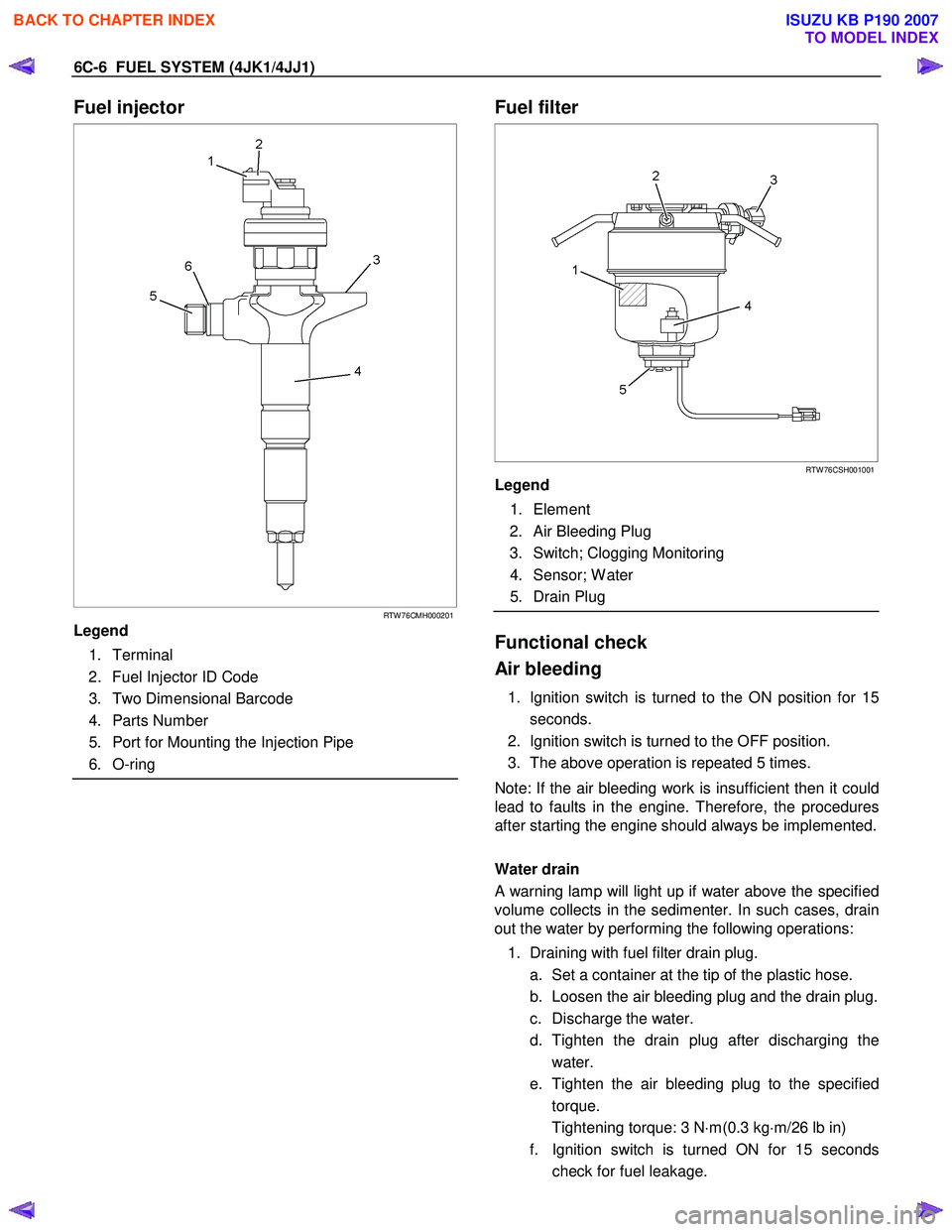
Fuel injector
RTW 76CMH000201
Legend
1. Terminal
2. Fuel Injector ID Code
3. Two Dimensional Barcode
4. Parts Number
5. Port for Mounting the Injection Pipe
6. O-ring
Fuel filter
RTW 76CSH001001
Legend
1. Element
2. Air Bleeding Plug
3. Switch; Clogging Monitoring
4. Sensor; W ater
5. Drain Plug
Functional check
Air bleeding
1. Ignition switch is turned to the ON position for 15 seconds.
2. Ignition switch is turned to the OFF position.
3. The above operation is repeated 5 times.
Note: If the air bleeding work is insufficient then it could
lead to faults in the engine. Therefore, the procedures
after starting the engine should always be implemented.
Water drain
A warning lamp will light up if water above the specified
volume collects in the sedimenter. In such cases, drain
out the water by performing the following operations:
1. Draining with fuel filter drain plug. a. Set a container at the tip of the plastic hose.
b. Loosen the air bleeding plug and the drain plug.
c. Discharge the water.
d. Tighten the drain plug after discharging the water.
e. Tighten the air bleeding plug to the specified torque.
Tightening torque: 3 N ⋅m(0.3 kg ⋅m/26 lb in)
f. Ignition switch is turned ON for 15 seconds check for fuel leakage.
BACK TO CHAPTER INDEX
TO MODEL INDEX
ISUZU KB P190 2007
Page 1554 of 6020
FUEL SYSTEM (4JK1/4JJ1) 6C-13
Fuel Filter Element
Removal
1. Detach the drain hose on the lower part of the fuel
filter or the drain plug, loosen the air bleed plug,
and drain the fuel from the fuel filter.
2. Detach the water-in-fuel switch harness.
3. Turn the element case counterclockwise to detach, and remove the filter element.
4. Replace the O-ring and confirm the snap-fit position, and fit a new filter element inside the
element case.
NOTE
It is strongly advisable to use the ISUZU/GM genuine
fuel filter for replacement.
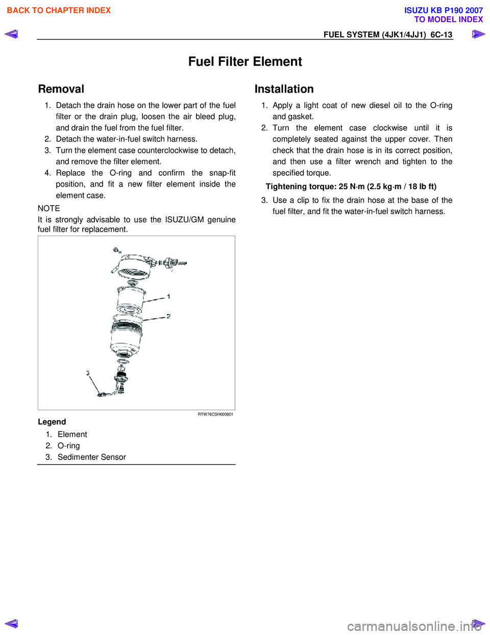
RTW 76CSH000901
Legend
1. Element
2. O-ring
3. Sedimenter Sensor
Installation
1. Apply a light coat of new diesel oil to the O-ring
and gasket.
2. Turn the element case clockwise until it is completely seated against the upper cover. Then
check that the drain hose is in its correct position,
and then use a filter wrench and tighten to the
specified torque.
Tightening torque: 25 N ⋅
⋅⋅
⋅
m (2.5 kg ⋅
⋅⋅
⋅
m / 18 lb ft)
3. Use a clip to fix the drain hose at the base of the fuel filter, and fit the water-in-fuel switch harness.
BACK TO CHAPTER INDEX
TO MODEL INDEX
ISUZU KB P190 2007
Page 1558 of 6020
FUEL SYSTEM (4JK1/4JJ1) 6C-17
Record the Fuel Injector ID Code Data from
each injector housing
1. Remove each fuel injector harness connector.
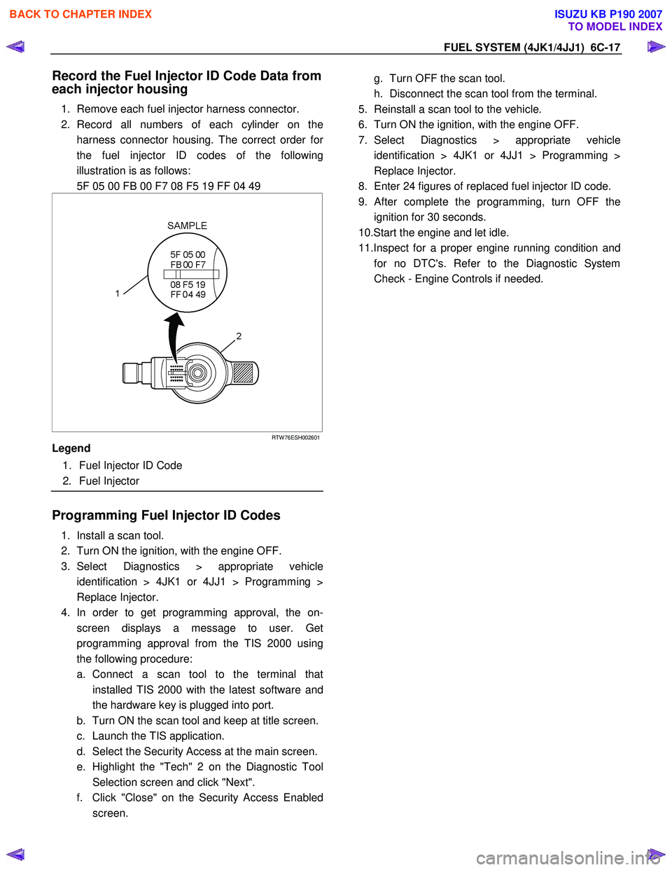
2. Record all numbers of each cylinder on the harness connector housing. The correct order fo
r
the fuel injector ID codes of the following
illustration is as follows:
5F 05 00 FB 00 F7 08 F5 19 FF 04 49
RTW 76ESH002601
Legend
1. Fuel Injector ID Code
2. Fuel Injector
Programming Fuel Injector ID Codes
1. Install a scan tool.
2. Turn ON the ignition, with the engine OFF.
3. Select Diagnostics > appropriate vehicle identification > 4JK1 or 4JJ1 > Programming >
Replace Injector.
4. In order to get programming approval, the on- screen displays a message to user. Get
programming approval from the TIS 2000 using
the following procedure:
a. Connect a scan tool to the terminal that installed TIS 2000 with the latest software and
the hardware key is plugged into port.
b. Turn ON the scan tool and keep at title screen.
c. Launch the TIS application.
d. Select the Security Access at the main screen.
e. Highlight the "Tech" 2 on the Diagnostic Tool Selection screen and click "Next".
f. Click "Close" on the Security Access Enabled screen.
g. Turn OFF the scan tool.
h. Disconnect the scan tool from the terminal.
5. Reinstall a scan tool to the vehicle.
6. Turn ON the ignition, with the engine OFF.
7. Select Diagnostics > appropriate vehicle identification > 4JK1 or 4JJ1 > Programming >
Replace Injector.
8. Enter 24 figures of replaced fuel injector ID code.
9.
After complete the programming, turn OFF the
ignition for 30 seconds.
10.Start the engine and let idle.
11.Inspect for a proper engine running condition and for no DTC's. Refer to the Diagnostic System
Check - Engine Controls if needed.
BACK TO CHAPTER INDEX
TO MODEL INDEX
ISUZU KB P190 2007
Page 1580 of 6020
FUEL SYSTEM (4JK1/4JJ1) 6C-39
Fuel Sedimenter Switch
Inspection
1. Check that there is continuity between the switch
connector terminals when the float in the fuel
sedimenter is above the water drain line.
2. Turn on the ignition switch, remove the fuel sedimenter connector, and connect the terminals
of the connectors on the harness side. Confirm
that the sedimenter warning lamp lights up.
If abnormalities are detected during the check, replace
the switch parts and carry out repairs in case o
f
defective connection between circuits or short circuits.
RTW 76CSH001101
Legend
1. Sensor
2. Connector on The Vehicle Side
3. Harness
4. Drain Valve
BACK TO CHAPTER INDEX
TO MODEL INDEX
ISUZU KB P190 2007
Page 1585 of 6020
6C-44 FUEL SYSTEM (4JK1/4JJ1)
Fuel Tube / Quick - Connector Fittings
Precautions
• Do not light a match or create a flame.
• Keep flames away from your work area to prevent
flammable materials from catching fire.
• Disconnect the battery ground cable to prevent
electrical shorts.
• Pre −treat the piping system or associated parts
from thermal damage or from spattering when
welding or similar heat −generating work.
Cautions During Work
Do not expose the assembly to battery electrolyte or do
not wipe the assembly with a cloth used to wipe off spilt
battery electrolyte.
Piping that has been splattered with battery electrolyte
or battery electrolyte soaked cloth that was wiped on the
piping cannot be used.
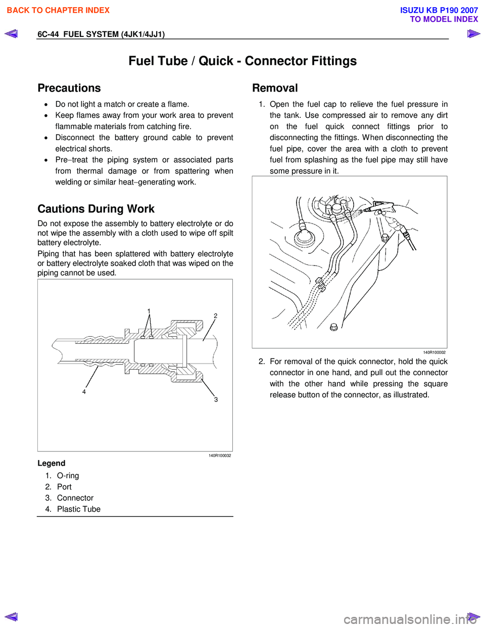
140R100032
Legend
1. O-ring
2. Port
3. Connector
4. Plastic Tube
Removal
1. Open the fuel cap to relieve the fuel pressure in
the tank. Use compressed air to remove any dirt
on the fuel quick connect fittings prior to
disconnecting the fittings. W hen disconnecting the
fuel pipe, cover the area with a cloth to prevent
fuel from splashing as the fuel pipe may still have
some pressure in it.
140R100002
2. For removal of the quick connector, hold the quick
connector in one hand, and pull out the connecto
r
with the other hand while pressing the square
release button of the connector, as illustrated.
BACK TO CHAPTER INDEX
TO MODEL INDEX
ISUZU KB P190 2007
Page 1586 of 6020
FUEL SYSTEM (4JK1/4JJ1) 6C-45
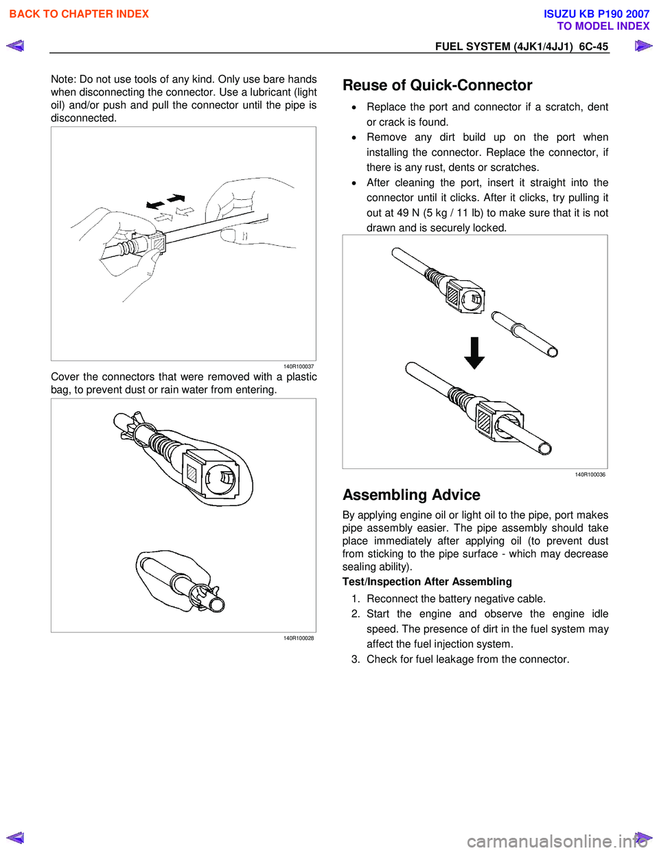
Note: Do not use tools of any kind. Only use bare hands
when disconnecting the connector. Use a lubricant (light
oil) and/or push and pull the connector until the pipe is
disconnected.
140R100037
Cover the connectors that were removed with a plastic
bag, to prevent dust or rain water from entering.
140R100028
Reuse of Quick-Connector
•
Replace the port and connector if a scratch, dent
or crack is found.
• Remove any dirt build up on the port when
installing the connector. Replace the connector, i
f
there is any rust, dents or scratches.
• After cleaning the port, insert it straight into the
connector until it clicks. After it clicks, try pulling it
out at 49 N (5 kg / 11 lb) to make sure that it is not
drawn and is securely locked.
140R100036
Assembling Advice
By applying engine oil or light oil to the pipe, port makes
pipe assembly easier. The pipe assembly should take
place immediately after applying oil (to prevent dust
from sticking to the pipe surface - which may decrease
sealing ability).
Test/Inspection After Assembling
1. Reconnect the battery negative cable.
2. Start the engine and observe the engine idle speed. The presence of dirt in the fuel system ma
y
affect the fuel injection system.
3. Check for fuel leakage from the connector.
BACK TO CHAPTER INDEX
TO MODEL INDEX
ISUZU KB P190 2007
Page 1595 of 6020
ENGINE ELECTRICAL (4JK1/4JJ1) 6D-7
Diagnosis
On-vehicle Inspection
The charging system warning light tells the vehicle
operator of possible problems with the system.
W hen the ignition switch is moved to the ON position,
the light turns on. The light turns off immediately afte
r
the engine is started. If the light turns on during engine
operation, there is a problem with the charging system.
Perform the checks described below.
1. Check the belt (broken or loose).
2. Check the harness connectors (loose o
r
disconnected).
3. W ith the engine off, turn the ignition switch to the ON position. If the warning lamp does not light,
remove the harness connector from the generator.
Ground the connector IG terminal. The lamp
should light. If it does not, the bulb is burned out.
Replace the bulb.
4. Start the engine. If the warning lamp remains on, the generator must be repaired or replaced.
BACK TO CHAPTER INDEX
TO MODEL INDEX
ISUZU KB P190 2007
Page 1627 of 6020
6E-10 ENGINE CONTROL SYSTEM (4JK1/4JJ1)
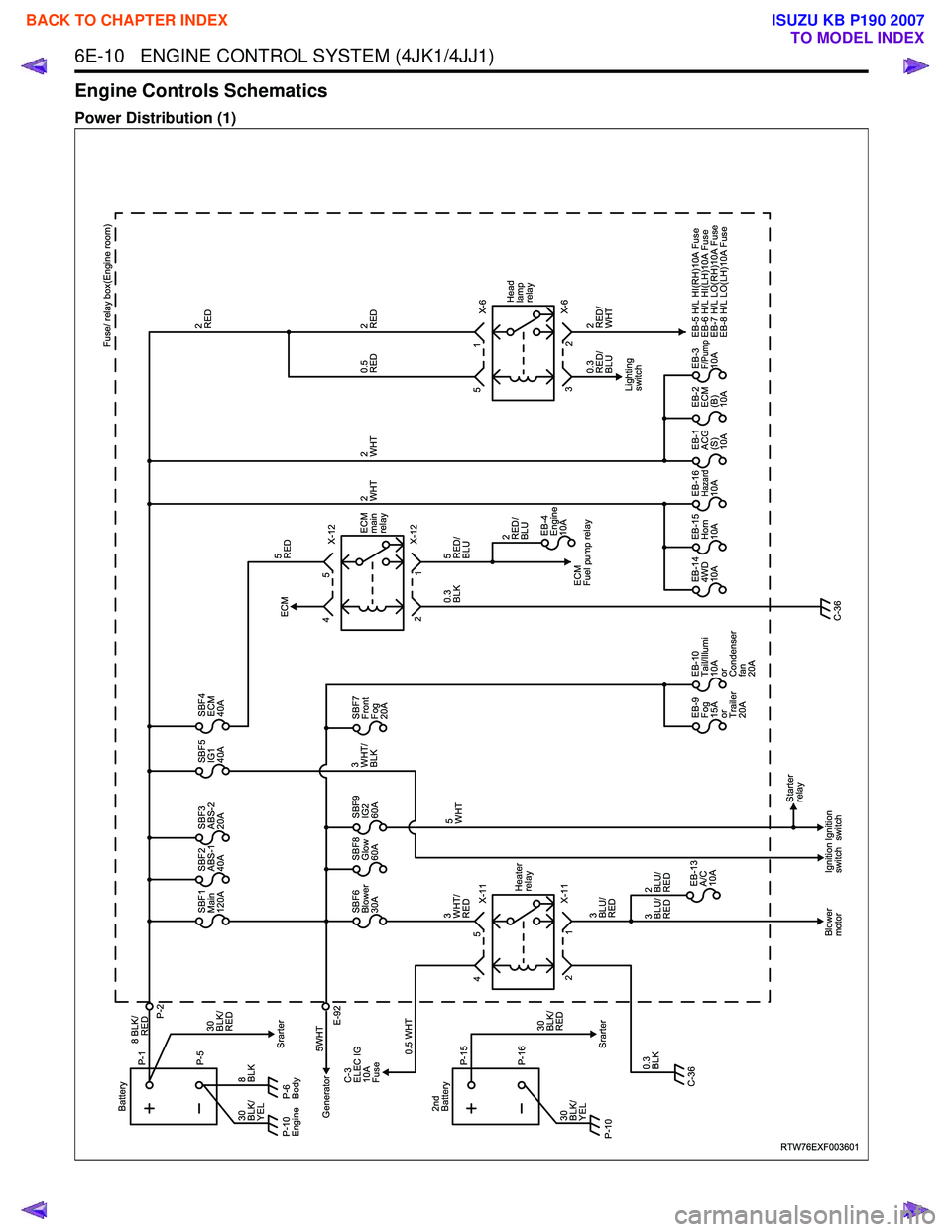
Engine Controls Schematics
Power Distribution (1)
RTW76EXF003601
X-11
X-11 Heater
relay
1
2
Blower
motor Ignition
switchIgnition
switch Starter
relay
SBF1
Main
120A SBF2
ABS-1
40A SBF3
ABS-2
20A SBF5
IG1
40A SBF4
ECM
40A
SBF6
Blower
30A
EB-13�
A/C
10A
2�
BLU/
RED
3�
BLU/
RED 3�
BLU/
RED SBF8
Glow
60A
SBF7
Front
Fog
20A
SBF9
IG2
60A
EB-9�
Fog
15A
or
Trailer
20AEB-10�
Tail/Illumi
10A
or
Condenser
fan
20A EB-4
Engine
10A
EB-14�
4WD
10A EB-15�
Horn
10A EB-16�
Hazard10A EB-1�
ACG
(S)
10AEB-2�
ECM
(B)
10AEB-3�
F/Pump10A
EB-5 H/L HI(RH)10A Fuse
EB-6 H/L HI(LH)10A Fuse
EB-7 H/L LO(RH)10A Fuse
EB-8 H/L LO(LH)10A Fuse
P-6
Body
Generator P-5
8 BLK/
P-1
P-2
Battery
8�
BLK 5WHTSrarter
Srarter
C-3
ELEC IG
10A
Fuse
E-92
0.5 WHT
0.3�
BLK 3�
WHT/
RED 5�
WHT
0.3�
BLK 5�
RED/
BLU
5�
RED
3�
WHT/
BLK
30�
BLK/
RED
30�
BLK/
YEL
P-10�
Engine
5
4 X-12
X-12
ECM
Fuel pump relay
ECM
ECM
main
relay
1
2 5
4
X-6
X-6
2�
RED/
WHT
0.3
RED/
BLU Fuse/ relay box(Engine room)
2�
RED
2�
RED
0.5�
RED
2�
WHT
2�
RED/
BLU 2�
WHT
2
3 1
5
Lighting
switch Head
lamp
relay
C-36 C-36
RED
P-16
P-15
2nd
Battery
30�
BLK/
YEL 30�
BLK/
RED
P-10�
BACK TO CHAPTER INDEX
TO MODEL INDEX
ISUZU KB P190 2007