2007 ISUZU KB P190 light
[x] Cancel search: lightPage 1966 of 6020
ENGINE CONTROL SYSTEM (4JK1/4JJ1) 6E-349
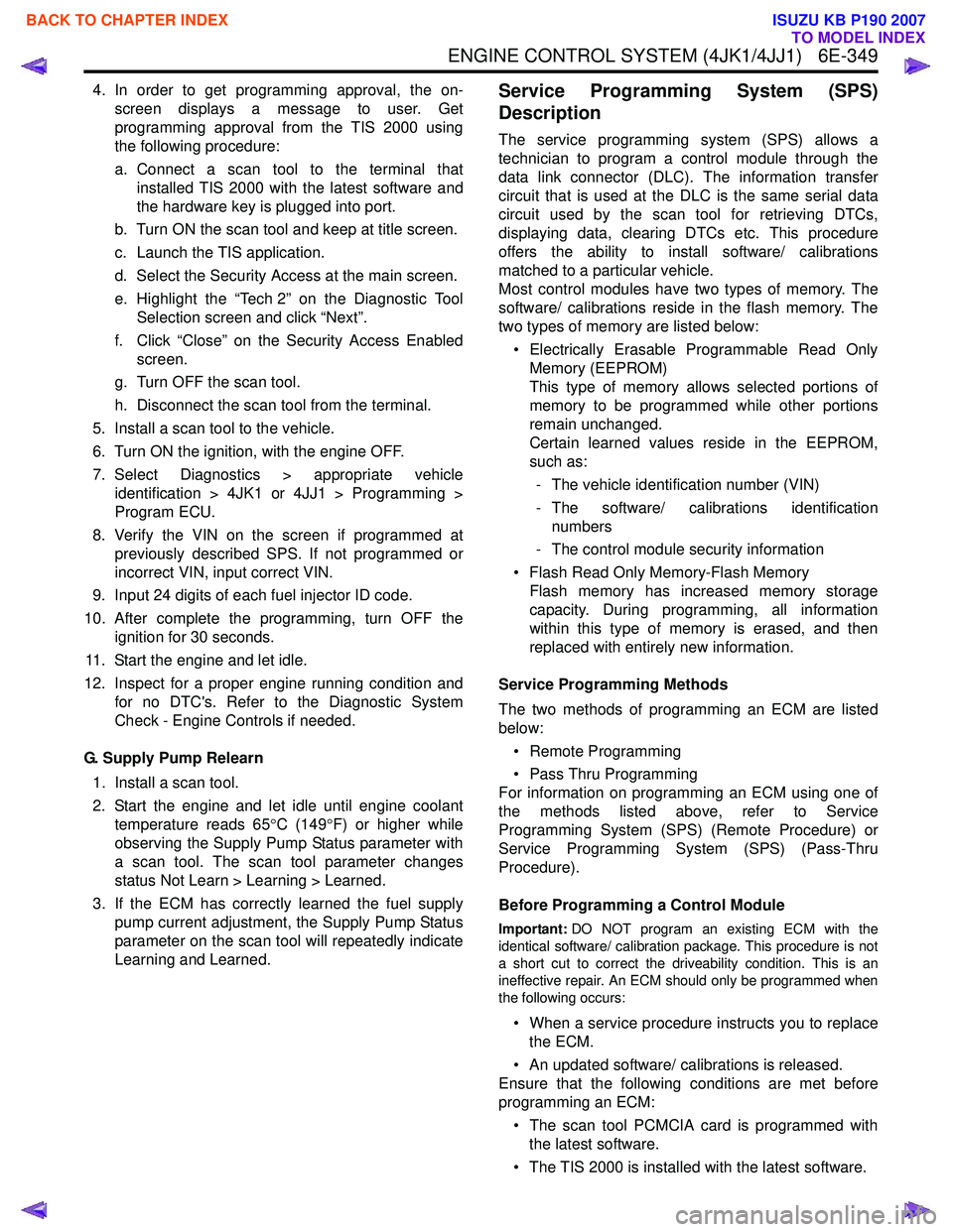
4. In order to get programming approval, the on-screen displays a message to user. Get
programming approval from the TIS 2000 using
the following procedure:
a. Connect a scan tool to the terminal that installed TIS 2000 with the latest software and
the hardware key is plugged into port.
b. Turn ON the scan tool and keep at title screen.
c. Launch the TIS application.
d. Select the Security Access at the main screen.
e. Highlight the “Tech 2” on the Diagnostic Tool Selection screen and click “Next”.
f. Click “Close” on the Security Access Enabled screen.
g. Turn OFF the scan tool.
h. Disconnect the scan tool from the terminal.
5. Install a scan tool to the vehicle.
6. Turn ON the ignition, with the engine OFF.
7. Select Diagnostics > appropriate vehicle identification > 4JK1 or 4JJ1 > Programming >
Program ECU.
8. Verify the VIN on the screen if programmed at previously described SPS. If not programmed or
incorrect VIN, input correct VIN.
9. Input 24 digits of each fuel injector ID code.
10. After complete the programming, turn OFF the ignition for 30 seconds.
11. Start the engine and let idle.
12. Inspect for a proper engine running condition and for no DTC's. Refer to the Diagnostic System
Check - Engine Controls if needed.
G. Supply Pump Relearn 1. Install a scan tool.
2. Start the engine and let idle until engine coolant temperature reads 65 °C (149 °F) or higher while
observing the Supply Pump Status parameter with
a scan tool. The scan tool parameter changes
status Not Learn > Learning > Learned.
3. If the ECM has correctly learned the fuel supply pump current adjustment, the Supply Pump Status
parameter on the scan tool will repeatedly indicate
Learning and Learned.Service Programming System (SPS)
Description
The service programming system (SPS) allows a
technician to program a control module through the
data link connector (DLC). The information transfer
circuit that is used at the DLC is the same serial data
circuit used by the scan tool for retrieving DTCs,
displaying data, clearing DTCs etc. This procedure
offers the ability to install software/ calibrations
matched to a particular vehicle.
Most control modules have two types of memory. The
software/ calibrations reside in the flash memory. The
two types of memory are listed below:
• Electrically Erasable Programmable Read Only Memory (EEPROM)
This type of memory allows selected portions of
memory to be programmed while other portions
remain unchanged.
Certain learned values reside in the EEPROM,
such as:
- The vehicle identification number (VIN)
- The software/ calibrations identification numbers
- The control module security information
• Flash Read Only Memory-Flash Memory Flash memory has increased memory storage
capacity. During programming, all information
within this type of memory is erased, and then
replaced with entirely new information.
Service Programming Methods
The two methods of programming an ECM are listed
below:
• Remote Programming
• Pass Thru Programming
For information on programming an ECM using one of
the methods listed above, refer to Service
Programming System (SPS) (Remote Procedure) or
Service Programming System (SPS) (Pass-Thru
Procedure).
Before Programming a Control Module
Important: DO NOT program an existing ECM with the
identical software/ calibration package. This procedure is not
a short cut to correct the driveability condition. This is an
ineffective repair. An ECM should only be programmed when
the following occurs:
• When a service procedure instructs you to replace the ECM.
• An updated software/ calibrations is released.
Ensure that the following conditions are met before
programming an ECM:
• The scan tool PCMCIA card is programmed with the latest software.
• The TIS 2000 is installed with the latest software.
BACK TO CHAPTER INDEX
TO MODEL INDEX
ISUZU KB P190 2007
Page 1967 of 6020
6E-350 ENGINE CONTROL SYSTEM (4JK1/4JJ1)
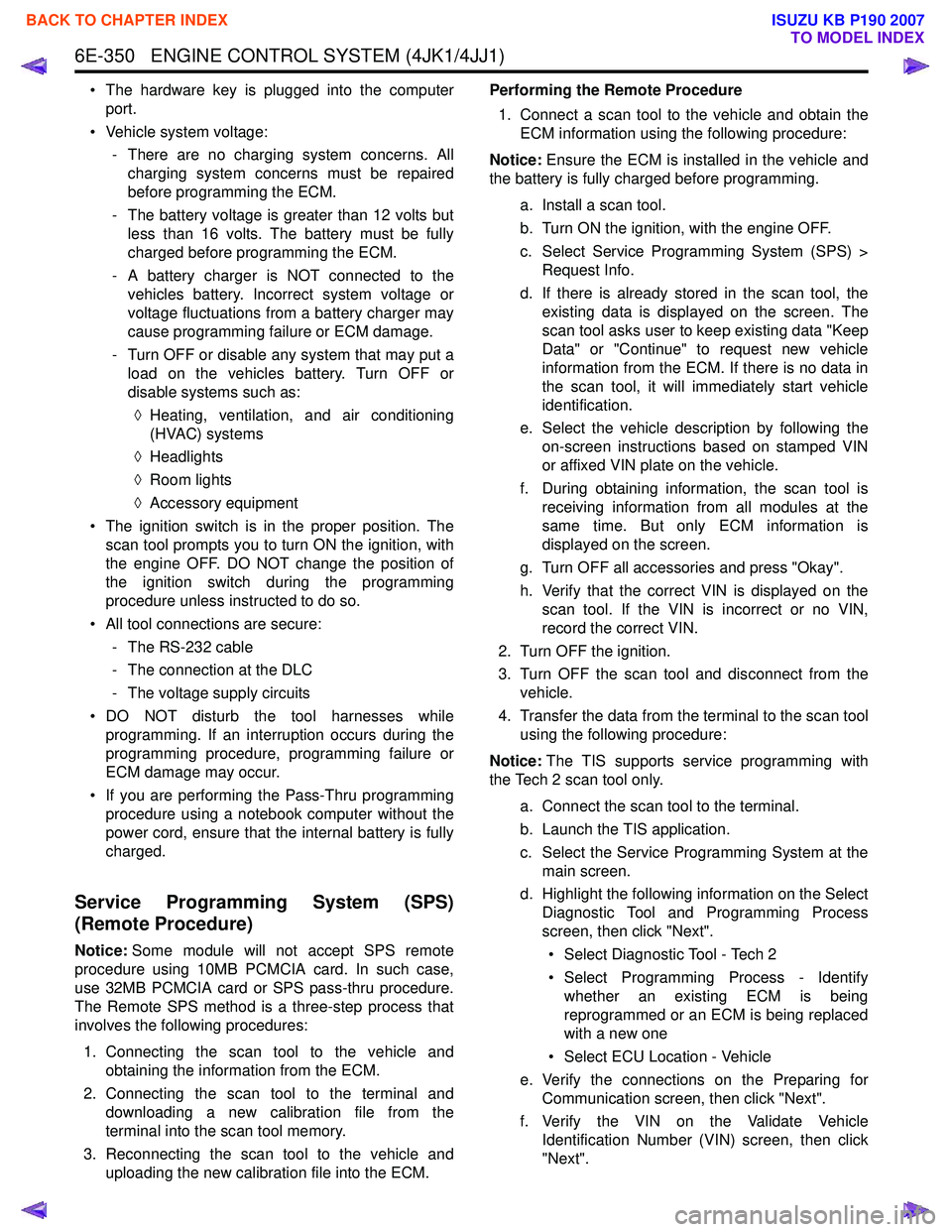
• The hardware key is plugged into the computerport.
• Vehicle system voltage: - There are no charging system concerns. Allcharging system concerns must be repaired
before programming the ECM.
- The battery voltage is greater than 12 volts but less than 16 volts. The battery must be fully
charged before programming the ECM.
- A battery charger is NOT connected to the vehicles battery. Incorrect system voltage or
voltage fluctuations from a battery charger may
cause programming failure or ECM damage.
- Turn OFF or disable any system that may put a load on the vehicles battery. Turn OFF or
disable systems such as:
◊ Heating, ventilation, and air conditioning
(HVAC) systems
◊ Headlights
◊ Room lights
◊ Accessory equipment
• The ignition switch is in the proper position. The scan tool prompts you to turn ON the ignition, with
the engine OFF. DO NOT change the position of
the ignition switch during the programming
procedure unless instructed to do so.
• All tool connections are secure: - The RS-232 cable
- The connection at the DLC
- The voltage supply circuits
• DO NOT disturb the tool harnesses while programming. If an interruption occurs during the
programming procedure, programming failure or
ECM damage may occur.
• If you are performing the Pass-Thru programming procedure using a notebook computer without the
power cord, ensure that the internal battery is fully
charged.
Service Programming System (SPS)
(Remote Procedure)
Notice: Some module will not accept SPS remote
procedure using 10MB PCMCIA card. In such case,
use 32MB PCMCIA card or SPS pass-thru procedure.
The Remote SPS method is a three-step process that
involves the following procedures:
1. Connecting the scan tool to the vehicle and obtaining the information from the ECM.
2. Connecting the scan tool to the terminal and downloading a new calibration file from the
terminal into the scan tool memory.
3. Reconnecting the scan tool to the vehicle and uploading the new calibration file into the ECM. Performing the Remote Procedure
1. Connect a scan tool to the vehicle and obtain the ECM information using the following procedure:
Notice: Ensure the ECM is installed in the vehicle and
the battery is fully charged before programming.
a. Install a scan tool.
b. Turn ON the ignition, with the engine OFF.
c. Select Service Programming System (SPS) > Request Info.
d. If there is already stored in the scan tool, the existing data is displayed on the screen. The
scan tool asks user to keep existing data "Keep
Data" or "Continue" to request new vehicle
information from the ECM. If there is no data in
the scan tool, it will immediately start vehicle
identification.
e. Select the vehicle description by following the on-screen instructions based on stamped VIN
or affixed VIN plate on the vehicle.
f. During obtaining information, the scan tool is receiving information from all modules at the
same time. But only ECM information is
displayed on the screen.
g. Turn OFF all accessories and press "Okay".
h. Verify that the correct VIN is displayed on the scan tool. If the VIN is incorrect or no VIN,
record the correct VIN.
2. Turn OFF the ignition.
3. Turn OFF the scan tool and disconnect from the vehicle.
4. Transfer the data from the terminal to the scan tool using the following procedure:
Notice: The TIS supports service programming with
the Tech 2 scan tool only.
a. Connect the scan tool to the terminal.
b. Launch the TIS application.
c. Select the Service Programming System at the main screen.
d. Highlight the following information on the Select Diagnostic Tool and Programming Process
screen, then click "Next".
• Select Diagnostic Tool - Tech 2
• Select Programming Process - Identify whether an existing ECM is being
reprogrammed or an ECM is being replaced
with a new one
• Select ECU Location - Vehicle
e. Verify the connections on the Preparing for Communication screen, then click "Next".
f. Verify the VIN on the Validate Vehicle Identification Number (VIN) screen, then click
"Next".
BACK TO CHAPTER INDEX
TO MODEL INDEX
ISUZU KB P190 2007
Page 1968 of 6020
ENGINE CONTROL SYSTEM (4JK1/4JJ1) 6E-351
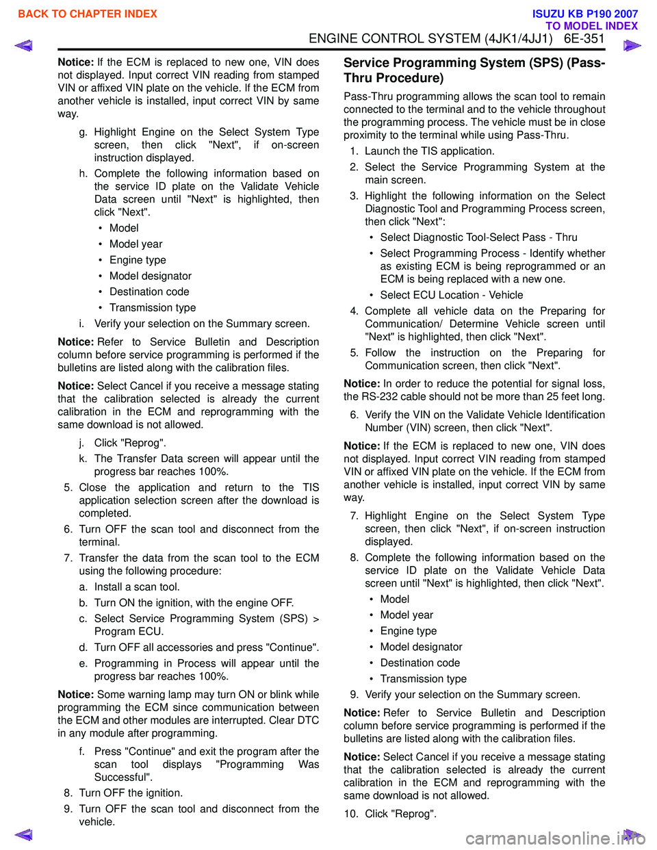
Notice:If the ECM is replaced to new one, VIN does
not displayed. Input correct VIN reading from stamped
VIN or affixed VIN plate on the vehicle. If the ECM from
another vehicle is installed, input correct VIN by same
way.
g. Highlight Engine on the Select System Typescreen, then click "Next", if on-screen
instruction displayed.
h. Complete the following information based on the service ID plate on the Validate Vehicle
Data screen until "Next" is highlighted, then
click "Next".
• Model
• Model year
• Engine type
• Model designator
• Destination code
• Transmission type
i. Verify your selection on the Summary screen.
Notice: Refer to Service Bulletin and Description
column before service programming is performed if the
bulletins are listed along with the calibration files.
Notice: Select Cancel if you receive a message stating
that the calibration selected is already the current
calibration in the ECM and reprogramming with the
same download is not allowed.
j. Click "Reprog".
k. The Transfer Data screen will appear until the progress bar reaches 100%.
5. Close the application and return to the TIS application selection screen after the download is
completed.
6. Turn OFF the scan tool and disconnect from the terminal.
7. Transfer the data from the scan tool to the ECM using the following procedure:
a. Install a scan tool.
b. Turn ON the ignition, with the engine OFF.
c. Select Service Programming System (SPS) > Program ECU.
d. Turn OFF all accessories and press "Continue".
e. Programming in Process will appear until the progress bar reaches 100%.
Notice: Some warning lamp may turn ON or blink while
programming the ECM since communication between
the ECM and other modules are interrupted. Clear DTC
in any module after programming.
f. Press "Continue" and exit the program after thescan tool displays "Programming Was
Successful".
8. Turn OFF the ignition.
9. Turn OFF the scan tool and disconnect from the vehicle.Service Programming System (SPS) (Pass-
Thru Procedure)
Pass-Thru programming allows the scan tool to remain
connected to the terminal and to the vehicle throughout
the programming process. The vehicle must be in close
proximity to the terminal while using Pass-Thru.
1. Launch the TIS application.
2. Select the Service Programming System at the main screen.
3. Highlight the following information on the Select Diagnostic Tool and Programming Process screen,
then click "Next":
• Select Diagnostic Tool-Select Pass - Thru
• Select Programming Process - Identify whether as existing ECM is being reprogrammed or an
ECM is being replaced with a new one.
• Select ECU Location - Vehicle
4. Complete all vehicle data on the Preparing for Communication/ Determine Vehicle screen until
"Next" is highlighted, then click "Next".
5. Follow the instruction on the Preparing for Communication screen, then click "Next".
Notice: In order to reduce the potential for signal loss,
the RS-232 cable should not be more than 25 feet long.
6. Verify the VIN on the Validate Vehicle Identification Number (VIN) screen, then click "Next".
Notice: If the ECM is replaced to new one, VIN does
not displayed. Input correct VIN reading from stamped
VIN or affixed VIN plate on the vehicle. If the ECM from
another vehicle is installed, input correct VIN by same
way.
7. Highlight Engine on the Select System Type screen, then click "Next", if on-screen instruction
displayed.
8. Complete the following information based on the service ID plate on the Validate Vehicle Data
screen until "Next" is highlighted, then click "Next".
• Model
• Model year
• Engine type
• Model designator
• Destination code
• Transmission type
9. Verify your selection on the Summary screen.
Notice: Refer to Service Bulletin and Description
column before service programming is performed if the
bulletins are listed along with the calibration files.
Notice: Select Cancel if you receive a message stating
that the calibration selected is already the current
calibration in the ECM and reprogramming with the
same download is not allowed.
10. Click "Reprog".
BACK TO CHAPTER INDEX
TO MODEL INDEX
ISUZU KB P190 2007
Page 2002 of 6020
6-2 ENGINE DIAGNOSIS (C24SE)
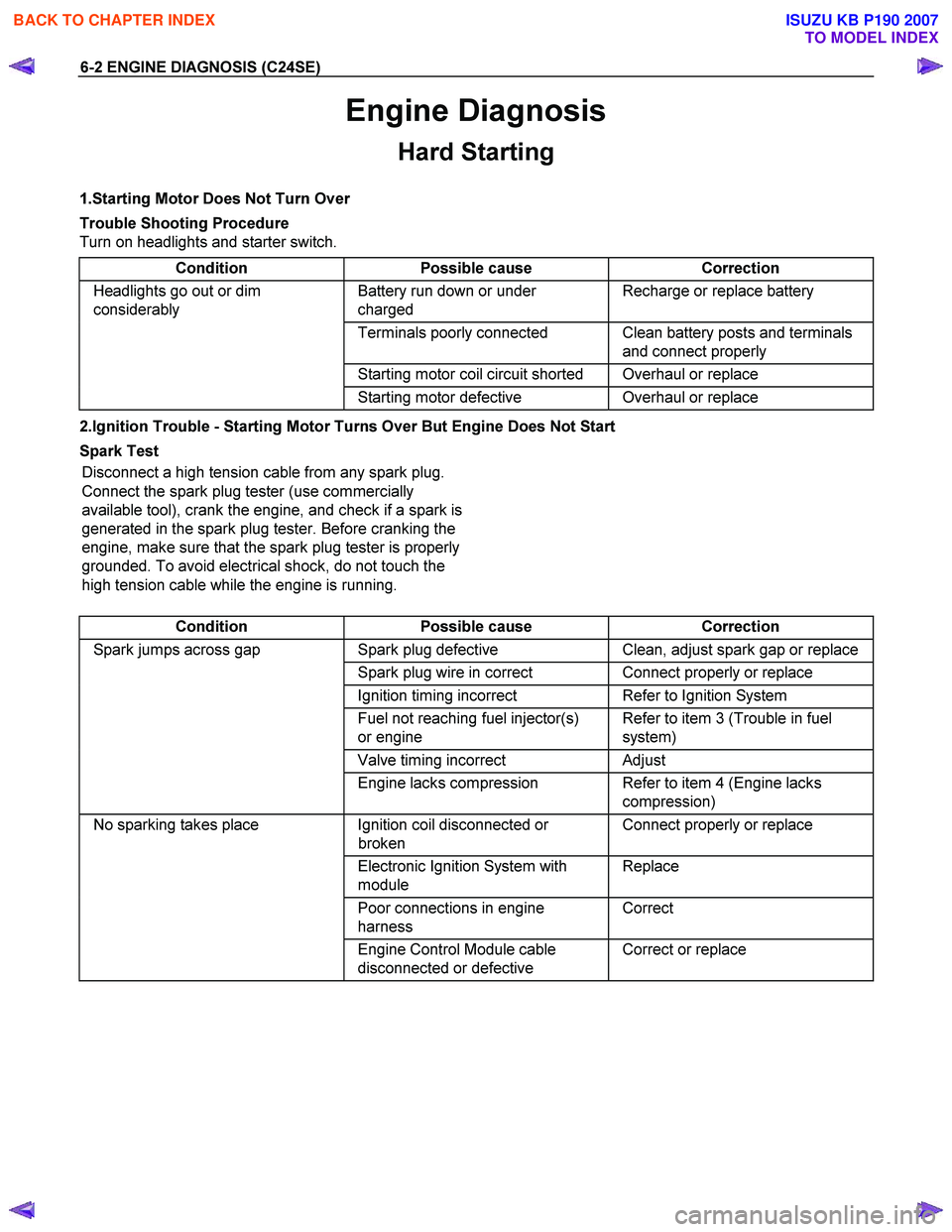
Engine Diagnosis
Hard Starting
1.Starting Motor Does Not Turn Over
Trouble Shooting Procedure
Turn on headlights and starter switch.
Condition Possible cause Correction
Headlights go out or dim
considerably Battery run down or under
charged Recharge or replace battery
Terminals poorly connected Clean battery posts and terminals
and connect properly
Starting motor coil circuit shorted Overhaul or replace
Starting motor defective Overhaul or replace
2.Ignition Trouble - Starting Motor Turns Over But Engine Does Not Start
Spark Test Disconnect a high tension cable from any spark plug.
Connect the spark plug tester (use commercially
available tool), crank the engine, and check if a spark is
generated in the spark plug tester. Before cranking the
engine, make sure that the spark plug tester is properly
grounded. To avoid electrical shock, do not touch the
high tension cable while the engine is running.
Condition Possible cause Correction
Spark jumps across gap Spark plug defective Clean, adjust spark gap or replace
Spark plug wire in correct Connect properly or replace
Ignition timing incorrect Refer to Ignition System
Fuel not reaching fuel injector(s)
or engine Refer to item 3 (Trouble in fuel
system)
Valve timing incorrect Adjust
Engine lacks compression Refer to item 4 (Engine lacks
compression)
No sparking takes place Ignition coil disconnected or
broken Connect properly or replace
Electronic Ignition System with
module Replace
Poor connections in engine
harness Correct
Engine Control Module cable
disconnected or defective Correct or replace
BACK TO CHAPTER INDEX
TO MODEL INDEX
ISUZU KB P190 2007
Page 2009 of 6020
ENGINE DIAGNOSIS (C24SE) 6-9
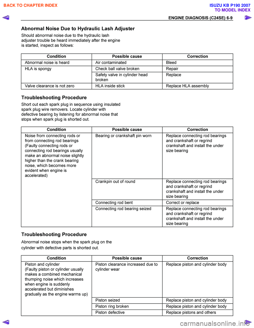
Abnormal Noise Due to Hydraulic Lash Adjuster
Should abnormal noise due to the hydraulic lash
adjuster trouble be heard immediately after the engine
is started, inspect as follows:
Condition Possible cause Correction
Abnormal noise is heard Air contaminated Bleed
HLA is spongy Check ball valve broken Repair
Safety valve in cylinder head
broken Replace
Valve clearance is not zero HLA inside stick
Replace HLA assembly
Troubleshooting Procedure
Short out each spark plug in sequence using insulated
spark plug wire removers. Locate cylinder with
defective bearing by listening for abnormal noise that
stops when spark plug is shorted out.
Condition Possible cause Correction
Noise from connecting rods or
from connecting rod bearings
(Faulty connecting rods or
connecting rod bearings usually
make an abnormal noise slightly
higher than the crank bearing
noise, which becomes more
evident when engine is
accelerated) Bearing or crankshaft pin worn Replace connecting rod bearings
and crankshaft or regrind
crankshaft and install the under
size bearing
Crankpin out of round Replace connecting rod bearings
and crankshaft or regrind
crankshaft and install the under
size bearing
Connecting rod bent Correct or replace
Connecting rod bearing seized Replace connecting rod bearings
and crankshaft or regrind
crankshaft and install the under
size bearing
Troubleshooting Procedure
Abnormal noise stops when the spark plug on the
cylinder with defective parts is shorted out.
Condition Possible cause Correction
Piston and cylinder
(Faulty piston or cylinder usually
makes a combined mechanical
thumping noise which increases
when engine is suddenly
accelerated but diminishes
gradually as the engine warms up) Piston clearance increased due to
cylinder wear Replace piston and cylinder body
Piston seized Replace piston and cylinder body
Piston ring broken Replace piston and cylinder body
Piston defective Replace pistons and others
BACK TO CHAPTER INDEX
TO MODEL INDEX
ISUZU KB P190 2007
Page 2032 of 6020
6A-18 ENGINE MECHANICAL (C24SE)
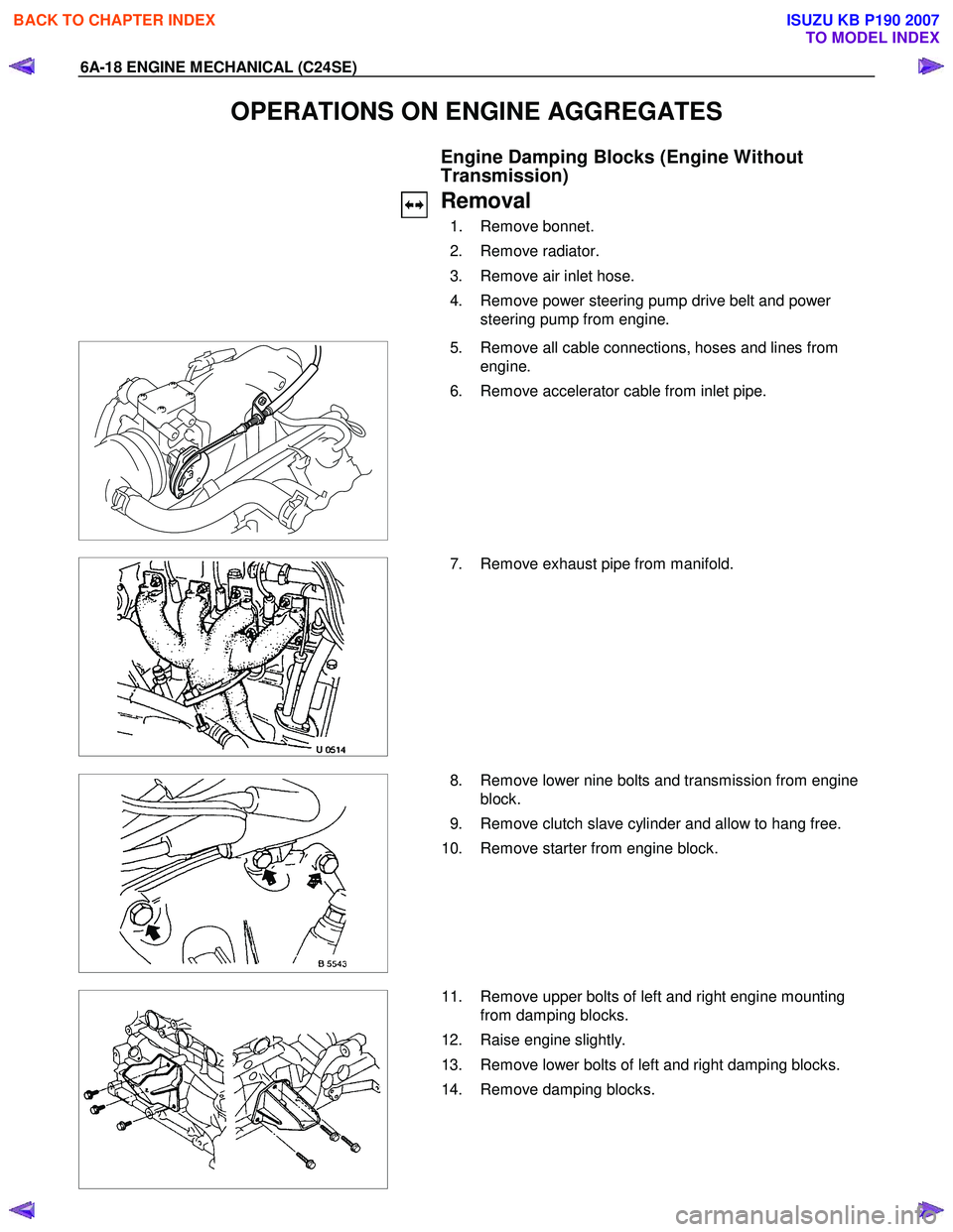
OPERATIONS ON ENGINE AGGREGATES
Engine Damping Blocks (Engine Without
Transmission)
Removal
1. Remove bonnet.
2. Remove radiator.
3. Remove air inlet hose.
4. Remove power steering pump drive belt and power steering pump from engine.
5. Remove all cable connections, hoses and lines from
engine.
6. Remove accelerator cable from inlet pipe.
7. Remove exhaust pipe from manifold.
8. Remove lower nine bolts and transmission from engine
block.
9. Remove clutch slave cylinder and allow to hang free.
10. Remove starter from engine block.
11. Remove upper bolts of left and right engine mounting
from damping blocks.
12. Raise engine slightly.
13. Remove lower bolts of left and right damping blocks.
14. Remove damping blocks.
BACK TO CHAPTER INDEX
TO MODEL INDEX
ISUZU KB P190 2007
Page 2041 of 6020
ENGINE MECHANICAL (C24SE) 6A-27
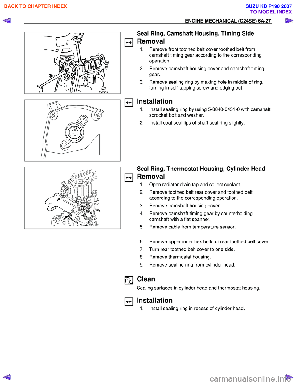
Seal Ring, Camshaft Housing, Timing Side
Removal
1. Remove front toothed belt cover toothed belt from camshaft timing gear according to the corresponding
operation.
2. Remove camshaft housing cover and camshaft timing gear.
3. Remove sealing ring by making hole in middle of ring, turning in self-tapping screw and edging out.
Installation
1. Install sealing ring by using 5-8840-0451-0 with camshaft sprocket bolt and washer.
2. Install coat seal lips of shaft seal ring slightly.
Seal Ring, Thermostat Housing, Cylinder Head
Removal
1. Open radiator drain tap and collect coolant.
2. Remove toothed belt rear cover and toothed belt according to the corresponding operation.
3. Remove camshaft housing cover.
4. Remove camshaft timing gear by counterholding camshaft with a flat spanner.
5. Remove cable from temperature sensor.
6. Remove upper inner hex bolts of rear toothed belt cover.
7. Turn rear toothed belt cover to one side.
8. Remove thermostat housing.
9. Remove sealing ring from cylinder head.
Clean
Sealing surfaces in cylinder head and thermostat housing.
Installation
1. Install sealing ring in recess of cylinder head.
BACK TO CHAPTER INDEX
TO MODEL INDEX
ISUZU KB P190 2007
Page 2042 of 6020
6A-28 ENGINE MECHANICAL (C24SE)
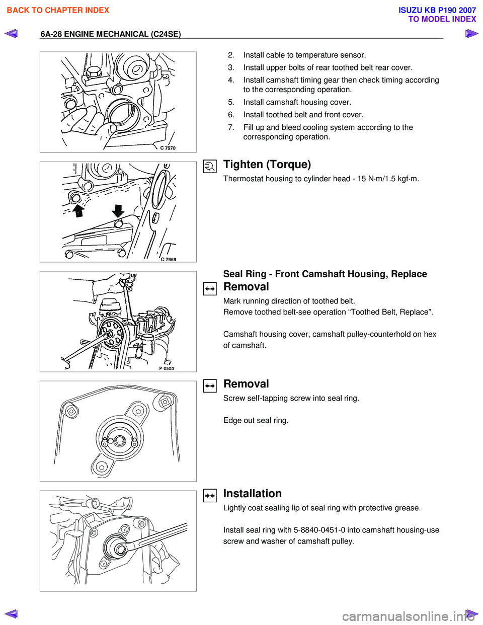
2. Install cable to temperature sensor.
3. Install upper bolts of rear toothed belt rear cover.
4. Install camshaft timing gear then check timing according to the corresponding operation.
5. Install camshaft housing cover.
6. Install toothed belt and front cover.
7. Fill up and bleed cooling system according to the corresponding operation.
Tighten (Torque)
Thermostat housing to cylinder head - 15 N ⋅m/1.5 kgf ⋅m.
Seal Ring - Front Camshaft Housing, Replace
Removal
Mark running direction of toothed belt.
Remove toothed belt-see operation “Toothed Belt, Replace”.
Camshaft housing cover, camshaft pulley-counterhold on hex
of camshaft.
Removal
Screw self-tapping screw into seal ring.
Edge out seal ring.
Installation
Lightly coat sealing lip of seal ring with protective grease.
Install seal ring with 5-8840-0451-0 into camshaft housing-use
screw and washer of camshaft pulley.
BACK TO CHAPTER INDEX
TO MODEL INDEX
ISUZU KB P190 2007