Page 1381 of 6020
ENGINE MECHANICAL (4JK1/4JJ1) 6A-21
Removal
1. Remove the engine hood.
2. Remove the engine cover.
3. Set the hoist and the engine hanger of the special tool (special tool 5-8840-2823-0).
4. Remove the engine mount.
• Before removing the engine mount, hang the engine with a hoist.
• Remove the bolts of the engine mount.
• Hoist the engine assembly slightly to remove the engine mount.
RTW 56ASH004501
Installation
1. Install the engine mount and tighten up with the
specified torque.
Tightening torque: 52 N ⋅
⋅⋅
⋅
m (5.3 kg ⋅
⋅⋅
⋅
m / 38 lb ft)
2. Install the engine cover.
3. Install the engine hood. • Check if nothing is wrong with the engine
mount by starting the engine.
BACK TO CHAPTER INDEX
TO MODEL INDEX
ISUZU KB P190 2007
Page 1414 of 6020
6A-54 ENGINE MECHANICAL (4JK1/4JJ1)
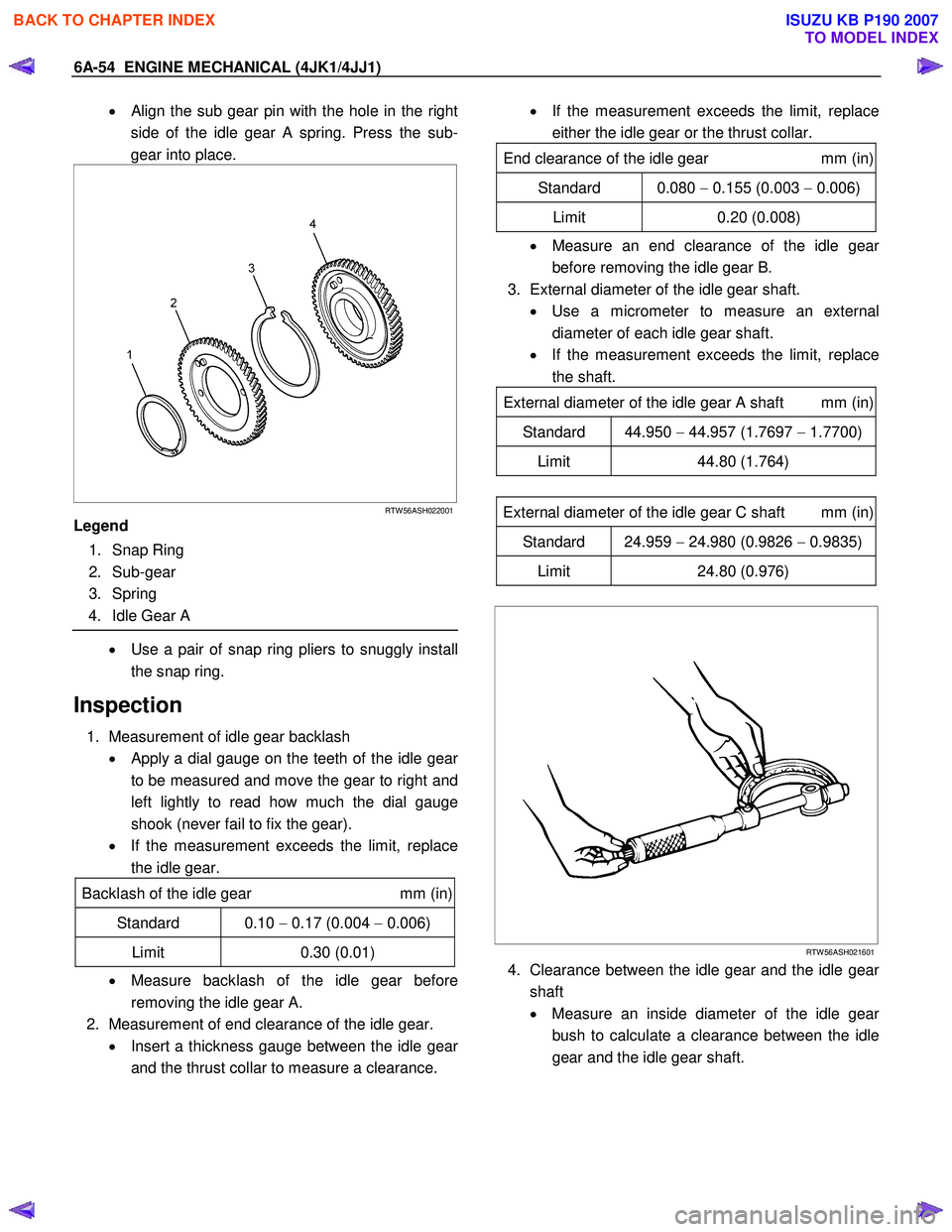
• Align the sub gear pin with the hole in the right
side of the idle gear A spring. Press the sub-
gear into place.
RTW 56ASH022001
Legend
1. Snap Ring
2. Sub-gear
3. Spring
4. Idle Gear A
• Use a pair of snap ring pliers to snuggly install
the snap ring.
Inspection
1. Measurement of idle gear backlash • Apply a dial gauge on the teeth of the idle gea
r
to be measured and move the gear to right and
left lightly to read how much the dial gauge
shook (never fail to fix the gear).
• If the measurement exceeds the limit, replace
the idle gear.
Backlash of the idle gear mm (in)
Standard 0.10 − 0.17 (0.004 − 0.006)
Limit 0.30 (0.01)
• Measure backlash of the idle gear before
removing the idle gear A.
2. Measurement of end clearance of the idle gear. • Insert a thickness gauge between the idle gea
r
and the thrust collar to measure a clearance.
• If the measurement exceeds the limit, replace
either the idle gear or the thrust collar.
End clearance of the idle gear mm (in)
Standard 0.080 − 0.155 (0.003 − 0.006)
Limit 0.20 (0.008)
• Measure an end clearance of the idle gear
before removing the idle gear B.
3. External diameter of the idle gear shaft. • Use a micrometer to measure an external
diameter of each idle gear shaft.
• If the measurement exceeds the limit, replace
the shaft.
External diameter of the idle gear A shaft mm (in)
Standard 44.950 − 44.957 (1.7697 − 1.7700)
Limit 44.80 (1.764)
External diameter of the idle gear C shaft mm (in)
Standard 24.959 − 24.980 (0.9826 − 0.9835)
Limit 24.80 (0.976)
RTW 56ASH021601
4. Clearance between the idle gear and the idle gear
shaft
• Measure an inside diameter of the idle gea
r
bush to calculate a clearance between the idle
gear and the idle gear shaft.
BACK TO CHAPTER INDEX
TO MODEL INDEX
ISUZU KB P190 2007
Page 1446 of 6020
6A-86 ENGINE MECHANICAL (4JK1/4JJ1)
014RY00027
Repair of the seat surface
• Remove carbon from the surface of the valve
insert seat.
• Use a seat cutter to minimize the scratch and
other roughness (15/45/75 degree-blade), thereb
y
returning the contact width to the standard value.
LNW 21BSH018201
Note:
Remove only scratches and roughness, and do not cut
the surface too much.
Use the free adjustment valve cutter pilot.
Do not let the valve cutter pilot waver inside the valve
guide.
Valve Seat Angle Degree
45
LNW 21BSH056101
• Attach compound in the valve insert seat.
• Insert the valve into the valve guide.
•
Attach compound on the valve seat surface, rotate
the valve and hit it lightly to grind it, and confirm
that it has even contact all round.
Note:
Remove compound completely after grinding.
LNW 21BSH031801
BACK TO CHAPTER INDEX
TO MODEL INDEX
ISUZU KB P190 2007
Page 1447 of 6020
ENGINE MECHANICAL (4JK1/4JJ1) 6A-87
Remove the valve seat insert
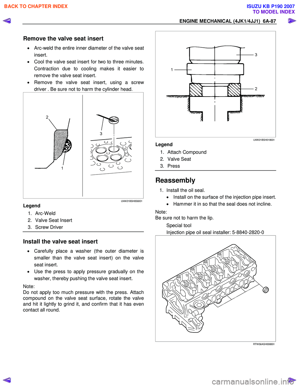
• Arc-weld the entire inner diameter of the valve seat
insert.
• Cool the valve seat insert for two to three minutes.
Contraction due to cooling makes it easier to
remove the valve seat insert.
• Remove the valve seat insert, using a scre
w
driver . Be sure not to harm the cylinder head.
LNW 21BSH056001
Legend
1. Arc-W eld
2. Valve Seat Insert
3. Screw Driver
Install the valve seat insert
• Carefully place a washer (the outer diameter is
smaller than the valve seat insert) on the valve
seat insert.
• Use the press to apply pressure gradually on the
washer, thereby pushing the valve seat insert.
Note:
Do not apply too much pressure with the press. Attach
compound on the valve seat surface, rotate the valve
and hit it lightly to grind it, and confirm that it has even
contact all round.
LNW 21BSH018601
Legend
1. Attach Compound
2. Valve Seat
3. Press
Reassembly
1. Install the oil seal.
• Install on the surface of the injection pipe insert.
• Hammer it in so that the seal does not incline.
Note:
Be sure not to harm the lip.
Special tool
Injection pipe oil seal installer: 5-8840-2820-0
RTW 56ASH008801
BACK TO CHAPTER INDEX
TO MODEL INDEX
ISUZU KB P190 2007
Page 1466 of 6020
6A-106 ENGINE MECHANICAL (4JK1/4JJ1)
LNW 21BSH009601
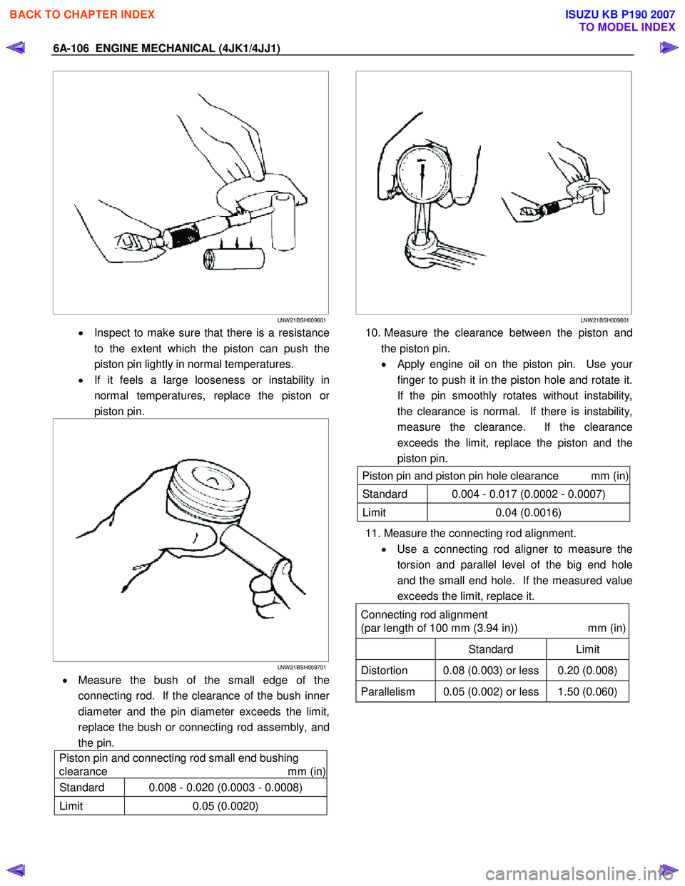
• Inspect to make sure that there is a resistance
to the extent which the piston can push the
piston pin lightly in normal temperatures.
• If it feels a large looseness or instability in
normal temperatures, replace the piston o
r
piston pin.
LNW 21BSH009701
• Measure the bush of the small edge of the
connecting rod. If the clearance of the bush inne
r
diameter and the pin diameter exceeds the limit,
replace the bush or connecting rod assembly, and
the pin.
Piston pin and connecting rod small end bushing
clearance mm (in)
Standard 0.008 - 0.020 (0.0003 - 0.0008)
Limit 0.05 (0.0020)
LNW 21BSH009801
10. Measure the clearance between the piston and
the piston pin.
•
Apply engine oil on the piston pin. Use your
finger to push it in the piston hole and rotate it.
If the pin smoothly rotates without instability,
the clearance is normal. If there is instability,
measure the clearance. If the clearance
exceeds the limit, replace the piston and the
piston pin.
Piston pin and piston pin hole clearance mm (in)
Standard 0.004 - 0.017 (0.0002 - 0.0007)
Limit 0.04 (0.0016)
11. Measure the connecting rod alignment.
• Use a connecting rod aligner to measure the
torsion and parallel level of the big end hole
and the small end hole. If the measured value
exceeds the limit, replace it.
Connecting rod alignment
(par length of 100 mm (3.94 in)) mm (in)
Standard Limit
Distortion 0.08 (0.003) or less 0.20 (0.008)
Parallelism 0.05 (0.002) or less 1.50 (0.060)
BACK TO CHAPTER INDEX
TO MODEL INDEX
ISUZU KB P190 2007
Page 1501 of 6020
ENGINE MECHANICAL (4JK1/4JJ1) 6A-141
Functional Check
Oil pressure check
1. Check whether the engine oil is contaminated with
dirt, light oil, or water. If contaminated with dirt,
light oil, or water (after examining the cause and
taking the appropriate measures for light oil o
r
water contamination), replace the oil.
2. Check the engine oil level. The oil level should be between the two holes of the level gauge. If the oil
level is insufficient, replenish it.
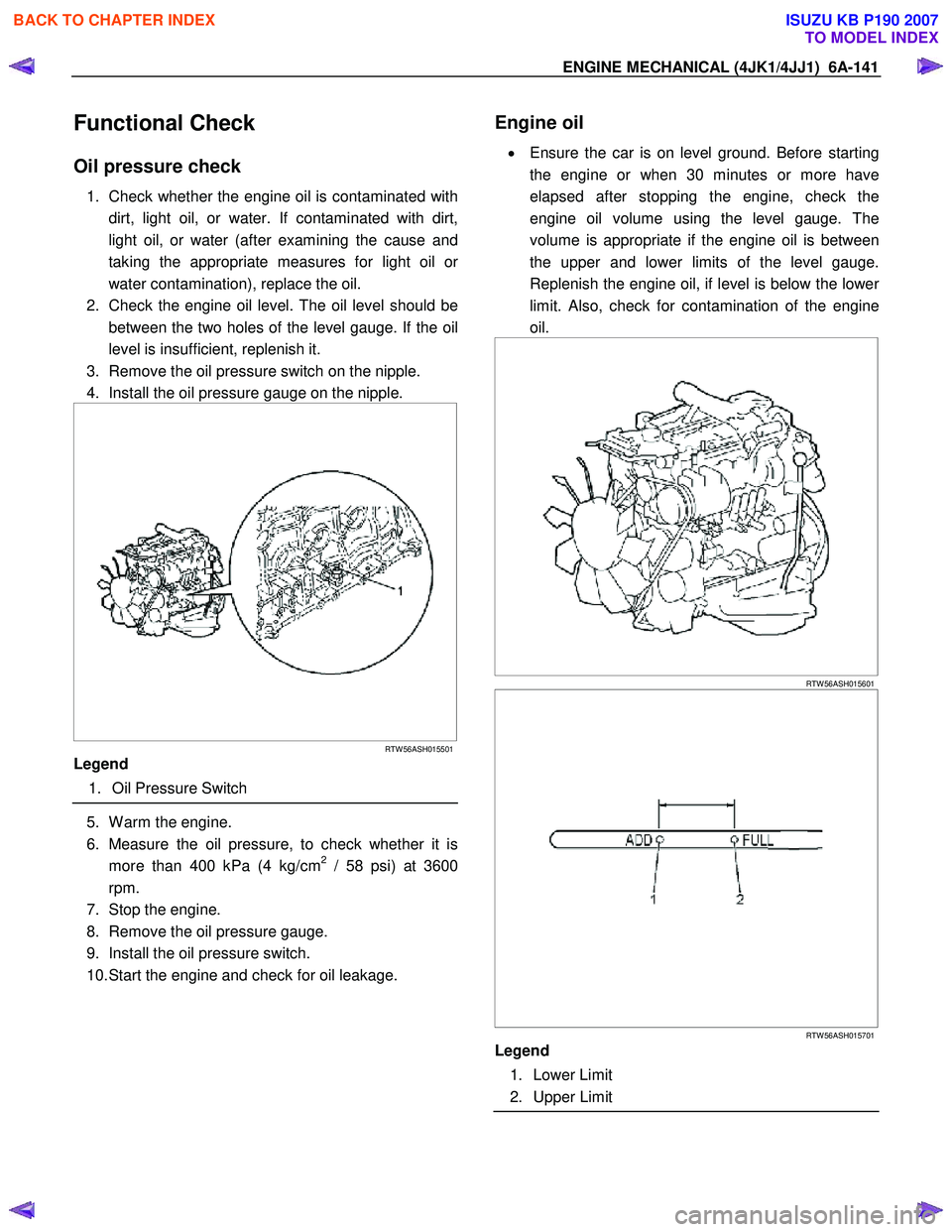
3. Remove the oil pressure switch on the nipple.
4. Install the oil pressure gauge on the nipple.
RTW 56ASH015501
Legend
1. Oil Pressure Switch
5. W arm the engine.
6. Measure the oil pressure, to check whether it is more than 400 kPa (4 kg/cm
2 / 58 psi) at 3600
rpm.
7. Stop the engine.
8. Remove the oil pressure gauge.
9. Install the oil pressure switch.
10. Start the engine and check for oil leakage.
Engine oil
•
Ensure the car is on level ground. Before starting
the engine or when 30 minutes or more have
elapsed after stopping the engine, check the
engine oil volume using the level gauge. The
volume is appropriate if the engine oil is between
the upper and lower limits of the level gauge.
Replenish the engine oil, if level is below the lowe
r
limit. Also, check for contamination of the engine
oil.
RTW 56ASH015601
RTW 56ASH015701
Legend
1. Lower Limit
2. Upper Limit
BACK TO CHAPTER INDEX
TO MODEL INDEX
ISUZU KB P190 2007
Page 1522 of 6020
6A-162 ENGINE MECHANICAL (4JK1/4JJ1)
Removal
1. Remove the oil pressure SW .
2. Remove the nipple; oil gallery.
3. Remove the nipple; oil pressure warning SW and gasket.
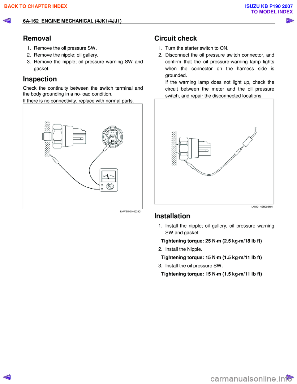
Inspection
Check the continuity between the switch terminal and
the body grounding in a no-load condition.
If there is no connectivity, replace with normal parts.
LNW 21HSH003301
Circuit check
1. Turn the starter switch to ON.
2. Disconnect the oil pressure switch connector, and confirm that the oil pressure-warning lamp lights
when the connector on the harness side is
grounded.
If the warning lamp does not light up, check the circuit between the meter and the oil pressure
switch, and repair the disconnected locations.
LNW 21HSH003401
Installation
1. Install the nipple; oil gallery, oil pressure warning
SW and gasket.
Tightening torque: 25 N ⋅
⋅⋅
⋅
m (2.5 kg ⋅
⋅⋅
⋅
m/18 lb ft)
2. Install the Nipple. Tightening torque: 15 N ⋅
⋅⋅
⋅
m (1.5 kg ⋅
⋅⋅
⋅
m/11 lb ft)
3. Install the oil pressure SW . Tightening torque: 15 N ⋅
⋅⋅
⋅
m (1.5 kg ⋅
⋅⋅
⋅
m/11 lb ft)
BACK TO CHAPTER INDEX
TO MODEL INDEX
ISUZU KB P190 2007
Page 1543 of 6020
6C-2 FUEL SYSTEM (4JK1/4JJ1)
Fuel System
Service Precautions
Parts of the fuel system such as the internal part of the
fuel injector, and holes and clearances that form
passages for fuel are finished to a very high degree o
f
accuracy. They are therefore highly sensitive to foreign
matter and the entry of foreign matter could cause
damage to the fuel passage. Therefore, effective
measures should be taken to prevent the entry o
f
foreign matter.
If a water removal agent is used in the fuel then it will
absorb moisture in the light oil and may cause rust.
Therefore, do not use a water removal agent in the fuel
tank.
W hen servicing the fuel system, every precaution must
be taken to prevent the entry of foreign material into the
system.
• Before beginning the service procedure, wash the
fuel line and the surrounding area.
• Perform the service procedures with clean hands.
Do not wear work gloves.
• Immediately after removing the fuel hose and/o
r
fuel pipe, carefully tape vinyl bags over the
exposed ends of the hose or pipe.
• If parts are to be replaced (fuel hose, fuel pipe,
etc.) do not open the new part packaging until
installation.
Discard gaskets and O-rings and replace them with ne
w
ones.
Work procedure
•
The fuel opening must be quickly sealed when
removing the fuel pipe, injection pipe, fuel injector,
fuel supply pump, and fuel rail.
• The eyebolts and gasket must be stored in a clean
parts box with a lid to prevent adhesion of foreign
matter.
• Fuel leakage could cause fires. Therefore, afte
r
finishing the work, wipe off the fuel that has leaked
out and make sure there is no fuel leakage afte
r
starting the engine.
BACK TO CHAPTER INDEX
TO MODEL INDEX
ISUZU KB P190 2007