2007 ISUZU KB P190 charging
[x] Cancel search: chargingPage 3446 of 6020
Engine Management – V6 – Diagnostics Page 6C1-2–168
• To assist diagnosis, refer to 3 W iring Diagrams and Connector Charts in this Section, for the system wiring
diagram and connector charts.
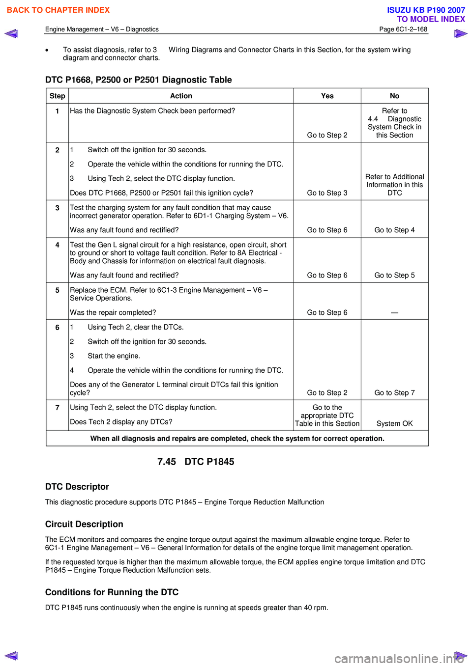
DTC P1668, P2500 or P2501 Diagnostic Table
Step Action Yes No
1 Has the Diagnostic System Check been performed?
Go to Step 2 Refer to
4.4 Diagnostic
System Check in this Section
2 1 Switch off the ignition for 30 seconds.
2 Operate the vehicle within the conditions for running the DTC.
3 Using Tech 2, select the DTC display function.
Does DTC P1668, P2500 or P2501 fail this ignition cycle? Go to Step 3 Refer to Additional
Information in this DTC
3 Test the charging system for any fault condition that may cause
incorrect generator operation. Refer to 6D1-1 Charging System – V6.
W as any fault found and rectified? Go to Step 6 Go to Step 4
4 Test the Gen L signal circuit for a high resistance, open circuit, short
to ground or short to voltage fault condition. Refer to 8A Electrical -
Body and Chassis for information on electrical fault diagnosis.
W as any fault found and rectified? Go to Step 6 Go to Step 5
5 Replace the ECM. Refer to 6C1-3 Engine Management – V6 –
Service Operations.
W as the repair completed? Go to Step 6 —
6 1 Using Tech 2, clear the DTCs.
2 Switch off the ignition for 30 seconds.
3 Start the engine.
4 Operate the vehicle within the conditions for running the DTC.
Does any of the Generator L terminal circuit DTCs fail this ignition
cycle? Go to Step 2 Go to Step 7
7 Using Tech 2, select the DTC display function.
Does Tech 2 display any DTCs? Go to the
appropriate DTC
Table in this Section System OK
When all diagnosis and repairs are completed, check the system for correct operation.
7.45 DTC P1845
DTC Descriptor
This diagnostic procedure supports DTC P1845 – Engine Torque Reduction Malfunction
Circuit Description
The ECM monitors and compares the engine torque output against the maximum allowable engine torque. Refer to
6C1-1 Engine Management – V6 – General Information for details of the engine torque limit management operation.
If the requested torque is higher than the maximum allowable torque, the ECM applies engine torque limitation and DTC
P1845 – Engine Torque Reduction Malfunction sets.
Conditions for Running the DTC
DTC P1845 runs continuously when the engine is running at speeds greater than 40 rpm.
BACK TO CHAPTER INDEX
TO MODEL INDEX
ISUZU KB P190 2007
Page 3528 of 6020
Engine Management – V6 – Service Operations Page 6C1-3–4
1 General Information
1.1 General Description
This Section describes the correct service procedures to repair and test components of the V6 engine management
system. Emphasis is placed on the proper procedures and repair of components related to this specific system.
For component description, operation and location, refer to 6C1-1 Engine Management – V6 – General Information.
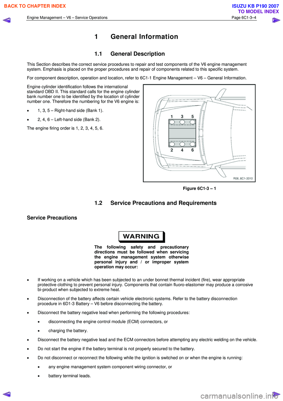
Engine cylinder identification follows the international
standard OBD II. This standard calls for the engine cylinder
bank number one to be identified by the location of cylinder
number one. Therefore the numbering for the V6 engine is:
• 1, 3, 5 – Right-hand side (Bank 1).
• 2, 4, 6 – Left-hand side (Bank 2).
The engine firing order is 1, 2, 3, 4, 5, 6.
Figure 6C1-3 – 1
1.2 Service Precautions and Requirements
Service Precautions
The following safety and precautionary
directions must be followed when servicing
the engine management system otherwise
personal injury and / or improper system
operation may occur:
• If working on a vehicle which has been subjected to an under bonnet thermal incident (fire), wear appropriate
protective clothing to prevent personal injury. Components that contain fluoro-elastomer may produce a corrosive
bi-product when subjected to extreme heat.
• Disconnection of the battery affects certain vehicle electronic systems. Refer to the battery disconnection
procedure in 6D1-3 Battery – V6 before disconnecting the battery.
• Disconnect the battery negative lead when performing the following procedures:
• disconnecting the engine control module (ECM) connectors, or
• charging the battery.
• Disconnect the battery negative lead and the ECM connectors before attempting any electric welding on the vehicle.
• Do not start the engine if the battery terminal is not properly secured to the battery.
• Do not disconnect or reconnect the following while the ignition is switched on or when the engine is running:
• any engine management system component wiring connector, or
• battery terminal leads.
BACK TO CHAPTER INDEX
TO MODEL INDEX
ISUZU KB P190 2007
Page 3588 of 6020
Charging System – V6 Page 6D1-1-1
6D1-1
Charging System – V6
ATTENTION
Before performing any service operations or other procedure described in this Section, refer to
1.2 WARNING, CAUTION and NOTES for correct workshop practices with regard to safety and / or
property damage.
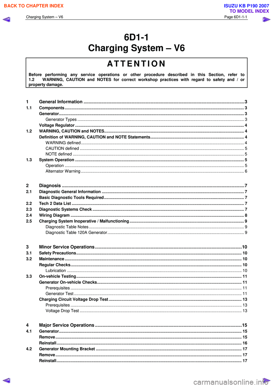
1 General Information ............................................................................................................ ...................3
1.1 Components ........................................................................................................................................................... 3
Generator................................................................................................................................................................ 3
Generator Types ................................................................................................................................................ 3
Voltage Regulator .................................................................................................................................................. 4
1.2 WARNING, CAUTION and NOTES..................................................................................................... .................... 4
Definition of WARNING, CAUTION and NOTE Statements............................................................................. .... 4
W ARNING defined ............................................................................................................................................. 4
CAUTION defined .............................................................................................................................................. 5
NOTE defined .................................................................................................................................................... 5
1.3 System Operation .................................................................................................................................................. 5
Operation ........................................................................................................................................................... 5
Alternator W arning ............................................................................................................. ................................ 6
2 Diagnosis ................................................................................................................................................7
2.1 Diagnostic General Information ........................................................................................................................... 7
Basic Diagnostic Tools Required ................................................................................................ ......................... 7
2.2 Tech 2 Data List ..................................................................................................................................................... 7
2.3 Diagnostic Systems Check ....................................................................................................... ............................ 7
2.4 Wiring Diagram ...................................................................................................................................................... 8
2.5 Charging System Inoperative / Malfunctioning ................................................................................................... 9
Diagnostic Table Notes ......................................................................................................... ............................. 9
Diagnostic Table 120A Generator ................................................................................................ ...................... 9
3 Minor Service Operations ....................................................................................................................10
3.1 Safety Precautions............................................................................................................................................... 10
3.2 Maintenance ......................................................................................................................................................... 10
Regular Checks................................................................................................................. ................................... 10
Lubrication ....................................................................................................................................................... 10
3.3 On-vehicle Testing ............................................................................................................. .................................. 11
Generator On-vehicle Checks.................................................................................................... ......................... 11
Prerequisites .................................................................................................................................................... 11
Generator Test ................................................................................................................................................. 11
Charging Circuit Voltage Drop Test ............................................................................................. ...................... 13
Prerequisites .................................................................................................................................................... 13
Voltage Drop Test ............................................................................................................................................ 13
4 Major Service Operations ....................................................................................................................15
4.1 Generator.............................................................................................................................................................. 15
Remove ................................................................................................................................................................. 15
Reinstall ................................................................................................................................................................ 16
4.2 Generator Mounting Bracket ..................................................................................................... ......................... 17
Remove ................................................................................................................................................................. 17
Reinstall ................................................................................................................................................................ 17
BACK TO CHAPTER INDEX
TO MODEL INDEX
ISUZU KB P190 2007
Page 3589 of 6020
Charging System – V6 Page 6D1-1-2
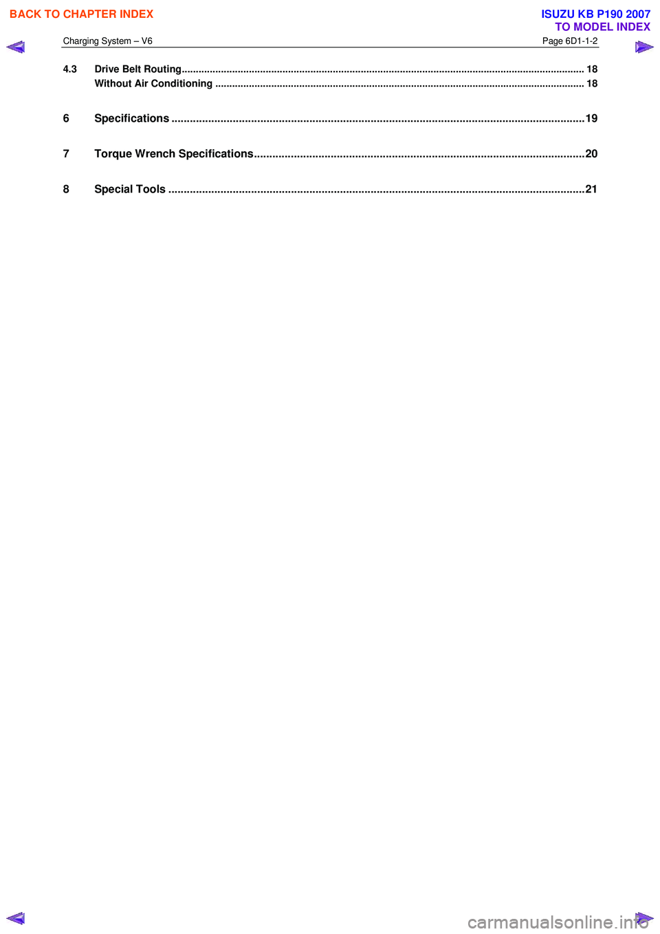
4.3 Drive Belt Routing................................................................................................................................................ 18
Without Air Conditioning ....................................................................................................... ............................. 18
6 Specifications .......................................................................................................................................19
7 Torque Wrench Specifications................................................................................................... .........20
8 Special Tools ........................................................................................................................................21
BACK TO CHAPTER INDEX
TO MODEL INDEX
ISUZU KB P190 2007
Page 3590 of 6020
Charging System – V6 Page 6D1-1-3
1 General Information
1.1 Components
Generator
The Mitsubishi generator can be identified visually by its two lower and one upper mounting lugs.
It is mounted to the lower right-hand side of the engine block. It is driven by the same drive belt that drives other engine
ancillaries and requires no periodic drive belt adjustment.
The generator has three phases, incorporating a rotor with six pole pairs fitted and two internal cooling fans; one on the
drive-end and one on the slip-ring end. The rotor is supported by ball bearings in both the drive and slip-ring end
housings. Surrounding the rotor is a stator, which has a three phase delta connected output winding construction on a
ring shaped lamination pack.
The output of the stator winding is rectified by eight diodes that are contained within the slip-ring end housing. Excitation
current is supplied to the rotor field coil via the voltage regulator, the brushes and slip-rings. The electronic voltage
regulator requires no adjustment in service.
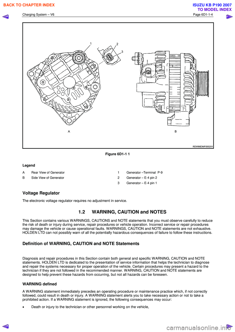
The generator has four external connections (refer to Figure 6D1-1 1):
• Generator – Terminal P-9 to the battery positive terminal P-1 via fuse SBF1,
• Generator – E-4 pin 1 to the ECM connection E-60 pin 43 – regulator monitoring,
• Generator – E-4 pin 2 to the ECM connection E60 pin 21 – battery voltage sensing, and
• ground connection via the installation bolts.
Generator Types
The vehicle is fitted with a 120 amp generator.
BACK TO CHAPTER INDEX
TO MODEL INDEX
ISUZU KB P190 2007
Page 3591 of 6020
Charging System – V6 Page 6D1-1-4
Figure 6D1-1 1
Legend
A Rear View of Generator
B Side View of Generator
1 Generator –Terminal P-9
2 Generator – E-4 pin 2
3 Generator – E-4 pin 1
Voltage Regulator
The electronic voltage regulator requires no adjustment in service.
1.2 WARNING, CAUTION and NOTES
This Section contains various W ARNINGS, CAUTIONS and NOTE statements that you must observe carefully to reduce
the risk of death or injury during service, repair procedures or vehicle operation. Incorrect service or repair procedures
may damage the vehicle or cause operational faults. W ARNINGS, CAUTION and NOTE statements are not exhaustive.
HOLDEN LTD can not possibly warn of all the potentially hazardous consequences of failure to follow these instructions.
Definition of WARNING, CAUTION and NOTE Statements
Diagnosis and repair procedures in this Section contain both general and specific W ARNING, CAUTION and NOTE
statements. HOLDEN LTD is dedicated to the presentation of service information that helps the technician to diagnose
and repair the systems necessary for proper operation of the vehicle. Certain procedures may present a hazard to the
technician if they are not followed in the recommended manner. W ARNING, CAUTION and NOTE statements are
designed to help prevent these hazards from occurring, but not all hazards can be foreseen.
WARNING defined
A W ARNING statement immediately precedes an operating procedure or maintenance practice which, if not correctly
followed, could result in death or injury. A W ARNING statement alerts you to take necessary action or not to take a
prohibited action. If a W ARNING statement is ignored, the following consequences may occur:
• Death or injury to the technician or other personnel working on the vehicle,
BACK TO CHAPTER INDEX
TO MODEL INDEX
ISUZU KB P190 2007
Page 3592 of 6020
Charging System – V6 Page 6D1-1-5
• Death or injury to other people in or near the workplace area, and / or
• Death or injury to the driver / or passenger(s) of the vehicle or other people, if the vehicle has been improperly
repaired.
CAUTION defined
A CAUTION statement immediately precedes an operating procedure or maintenance practice which, if not correctly
followed, could result in damage to or destruction of equipment, or corruption of data. If a CAUTION statement is
ignored, the following consequences may occur:
• Damage to the vehicle,
• Unnecessary vehicle repairs or component replacement,
• Faulty operation or performance of any system or component being repaired,
• Damage to any system or components which depend on the proper operation of the system or component being
repaired,
• Faulty operation or performance of any systems or components which depend on the proper operation or
performance of the system or component under repair,
• Damage to fasteners, basic tools or special tools and / or
• Leakage of coolant, lubricant or other vital fluids.
NOTE defined
A NOTE statement immediately precedes or follows an operating procedure, maintenance practice or condition that
requires highlighting. A NOTE statement also emphasises necessary characteristics of a diagnostic or repair procedure.
A NOTE statement is designed to:
• Clarify a procedure,
• Present additional information for accomplishing a procedure,
• Give insight into the reasons for performing a procedure in the recommended manner, and / or
• Present information that gives the technician the benefit of past experience in accomplishing a procedure with
greater ease.
1.3 System Operation
Operation
W ith the ignition switch in the ON position and the engine at rest, current is supplied via the regulator to generator
connector E-4 pin 1 and to the engine control module ECM connector E-60 pin 43. This initiates current flow (within the
regulator) from the generator connection P-9, to the brushes and rotor winding, to ‘excite’ the circuit.
The current in the rotor winding creates magnetic fields between adjacent rotor poles.
W ith the engine running, the rotor spins, the stator windings cut through this field and induce voltage. As the engine
speed is increased, this induced voltage increases. Current then flows through the three-phase diode bridge in the
rectifier to convert the AC voltage to DC. This is supplied to the generator connector P-9 output and then to the battery
terminal via fuse SBF1.
The regulator monitors the voltage to the battery. W hen this voltage reaches approximately 14.5 V, the regulator opens
the circuit through the rotor winding, causing the generator output voltage to drop. W hen the regulator senses a voltage
below a preset voltage, the regulator closes the circuit through the rotor winding and voltage to the battery again
increases. This cycle repeats very rapidly.
BACK TO CHAPTER INDEX
TO MODEL INDEX
ISUZU KB P190 2007
Page 3593 of 6020
Charging System – V6 Page 6D1-1-6
Alternator Warning
NOTE
All generator faults are displayed as
Check Alternator W arning on the instrument
cluster MFD, refer to 8A Electrical Body and
Chassis.
The ECM monitors the voltage on connector E-60 pin 21 and pin 43.
The voltage at the generator connector E-4 pin 2 will remain low when a fault condition is detected in the generator or
associated external circuits. The voltage remains low (while the ignition switch is on) until the fault is repaired.
NOTE
For more information on the alternator warning
refer to 8A Electrical Body and Chassis.
Fault conditions include the following:
• open circuit or excessive voltage drop in circuit 1,
• open circuit in the generator phase connection,
• overcharging conditions,
• short circuit in the regulator output stage,
• open circuit in the rotor winding,
• poor contact between the rectifier and the regulator, and / or
• high resistance in the fusible link assembly.
BACK TO CHAPTER INDEX
TO MODEL INDEX
ISUZU KB P190 2007