2007 ISUZU KB P190 charging
[x] Cancel search: chargingPage 3648 of 6020
Battery Page 6D1-3–8
Step Action Yes No
5
Perform the hydrometer test, refer to 3.3 Hydrometer Test.
Is the battery fully charged? Go to Step 6 Fully charge the
battery, refer to 4.2 Battery
Charge
6 Load test the battery, refer to 3.4 Load Test.
Does the battery pass the load test? Battery Serviceable.
Refer to:
6D1–1 Charging System – V6. Replace the battery,
refer to 4.1
Battery
When all diagnosis and repairs are completed, check the system for correct operation.
3.2 Battery Inspection
1 Read and obey the safety precautions for working with batteries, refer to 2 Safety Precautions.
2 Check the battery terminals and around the battery area for corrosion deposits. Remove any deposits as follows: a Scrub the area with a stiff brush.
b Treat the area with a solution of warm water and baking soda or ammonia.
c Rinse with clean water.
3 Check the battery posts, if they are loose, burned, pitted or damaged in any way replace the battery. Refer to 4.1 Battery.
4 Check the battery case, if it is cracked or damaged replace the battery. Refer to 4.1 Battery.
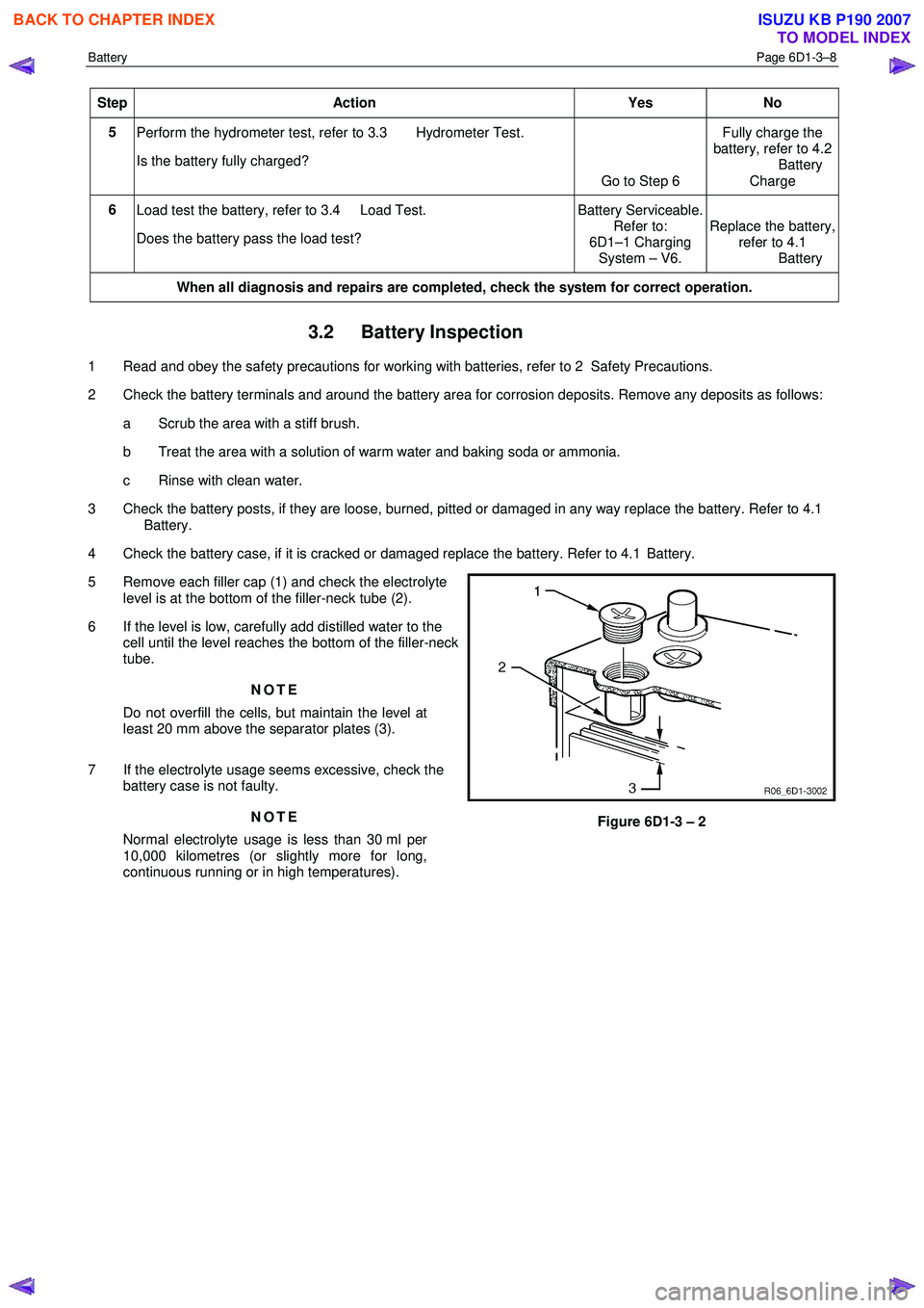
5 Remove each filler cap (1) and check the electrolyte level is at the bottom of the filler-neck tube (2).
6 If the level is low, carefully add distilled water to the cell until the level reaches the bottom of the filler-neck
tube.
NOTE
Do not overfill the cells, but maintain the level at
least 20 mm above the separator plates (3).
7 If the electrolyte usage seems excessive, check the battery case is not faulty.
NOTE
Normal electrolyte usage is less than 30 ml per
10,000 kilometres (or slightly more for long,
continuous running or in high temperatures).
Figure 6D1-3 – 2
BACK TO CHAPTER INDEX
TO MODEL INDEX
ISUZU KB P190 2007
Page 3650 of 6020
Battery Page 6D1-3–10
6 Still holding the hydrometer vertically, record the reading.
7 Put the electrolyte back into the cell.
8 Repeat steps 3 to 7 for each cell.
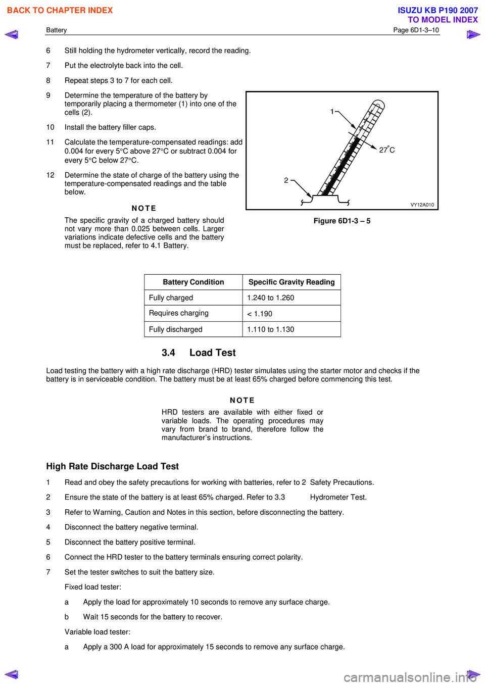
9 Determine the temperature of the battery by temporarily placing a thermometer (1) into one of the
cells (2).
10 Install the battery filler caps.
11 Calculate the temperature-compensated readings: add 0.004 for every 5 °C above 27 °C or subtract 0.004 for
every 5 °C below 27 °C.
12 Determine the state of charge of the battery using the temperature-compensated readings and the table
below.
NOTE
The specific gravity of a charged battery should
not vary more than 0.025 between cells. Larger
variations indicate defective cells and the battery
must be replaced, refer to 4.1 Battery.
Figure 6D1-3 – 5
Battery Condition Specific Gravity Reading
Fully charged 1.240 to 1.260
Requires charging < 1.190
Fully discharged 1.110 to 1.130
3.4 Load Test
Load testing the battery with a high rate discharge (HRD) tester simulates using the starter motor and checks if the
battery is in serviceable condition. The battery must be at least 65% charged before commencing this test.
NOTE
HRD testers are available with either fixed or
variable loads. The operating procedures may
vary from brand to brand, therefore follow the
manufacturer’s instructions.
High Rate Discharge Load Test
1 Read and obey the safety precautions for working with batteries, refer to 2 Safety Precautions.
2 Ensure the state of the battery is at least 65% charged. Refer to 3.3 Hydrometer Test.
3 Refer to W arning, Caution and Notes in this section, before disconnecting the battery.
4 Disconnect the battery negative terminal.
5 Disconnect the battery positive terminal.
6 Connect the HRD tester to the battery terminals ensuring correct polarity.
7 Set the tester switches to suit the battery size. Fixed load tester:
a Apply the load for approximately 10 seconds to remove any surface charge.
b W ait 15 seconds for the battery to recover.
Variable load tester:
a Apply a 300 A load for approximately 15 seconds to remove any surface charge.
BACK TO CHAPTER INDEX
TO MODEL INDEX
ISUZU KB P190 2007
Page 3655 of 6020
Battery Page 6D1-3–15
5 Install the positive terminal onto the positive battery post. Ensure the terminal sits below the top of the post and
tighten the terminal nut to the correct specification.
Battery terminal nut
torque specification .....................................2.0 – 5.0 Nm
6 Install the negative terminal onto the negative battery post. Ensure the terminal sits below the top of the post and tighten the terminal nut to the correct specification.
Battery terminal nut
torque specification .....................................2.0 – 5.0 Nm
7 Smear the battery posts and cable terminals with petroleum jelly to inhibit corrosion.
4.2 Battery Charge
Safety Precautions
Read and obey the general safety precautions for working with batteries, refer to 2 Safety Precautions.
The battery releases an explosive hydrogen and oxygen gas mixture during charging. Ensure there are no naked flames
or sparks near the battery.
Flat batteries can be safely boost-charged, however avoid excessive charging current if the battery is more than half
charged. Slow charging is best.
Fast charging can substantially boost a battery, but slow charging is required to fully charge the battery.
Do not use a fast charger:
• for starting the vehicle,
• if the specific gravity readings are not uniform between battery cells, refer to 3.3 Hydrometer Test,
• if the specific gravity readings are above 1.20, refer to 3.3Hydrometer Test,
• if the electrolyte is discoloured with brown sediment, and
• if any of the above three conditions develop after beginning a fast charge.
Battery Charge Procedure
Disconnection of the battery affects certain
vehicle electronic systems. Refer to Warning,
Caution and Notes in this section before
disconnecting the battery.
1 Perform steps 1 to 10 of the battery inspection, refer to 3.2 Battery Inspection.
2 Remove the battery from the vehicle. Refer to 4.1 Battery.
3 If required remove the battery filler caps. Let the caps rest loosely on top of the filler tubes.
Always ensure the connections are to the
correct polarity and follow the manufacturer’s
recommendations for battery charging.
4 Connect the battery to the battery charger.
5 Set the charging current using the following table as a guide.
BACK TO CHAPTER INDEX
TO MODEL INDEX
ISUZU KB P190 2007
Page 3656 of 6020
Battery Page 6D1-3–16
NOTE
Charging a battery at higher current rates can
significantly reduce the life of the battery.
Charge Rate Initial Current Maximum Time Required
Slow charge 4 A 24 hours
Fast charge 35 A 2 hours
6 After a few minutes, check the colour and specific gravity of the electrolyte. Refer to 3.3 Hydrometer Test.
7 Monitor the electrolyte temperature while the battery is charging. If the electrolyte temperature reaches 55 °C:
a switch the charging current off,
b allow the battery to cool,
c reduce the charging current, and
d restart charging the battery.
NOTE
For the best results, charge the battery with the
electrolyte and plates at room temperature. An
extremely cold battery may not appear to accept
current for several hours after starting the battery
charger. If the battery does not appear to accept
charge after several hours replace the battery.
8 For slow charging check the voltage and specific gravity each hour or more regularly for fast charging. Stop the charging when there is no change in voltage or electrolyte specific gravity over three checks.
9 If the battery was fast charged connect the battery to a slow-charger for a few hours to bring the battery to the fully charged condition. Ensure the last few hours of charge do not exceed 1 A.
10 Tighten the filler caps. Ensure they are secure.
11 Install the battery in the vehicle. Refer to 4.1 Battery.
4.3 Emergency Jump Starting Procedure
Safety Precautions
• Read and obey the general safety precautions for working with batteries, refer to 2 Safety Precautions.
• Do not allow the vehicles to touch each other during the jump starting procedure.
• Ensure the assisting vehicle battery has the same voltage rating and connects negative to ground. If this is not the
case, serious injury and damage to electrical equipment can result.
• Do not push or tow the vehicle to start it. Damage can result when unburnt fuel reaches the catalytic converter and
ignites.
• Do not start the vehicle using a fast charger.
• W hen using jumper leads, treat both the booster battery and the discharged battery with care.
• Do not allow sparks, flame or smoking near the battery.
• Ensure that metal tools or jumper cables do not simultaneously contact the battery positive terminal and any other
metal part of the vehicle.
Jump Starting Procedure
1 Position the assisting vehicle so the batteries of both vehicles are close together, refer to Figure 6D1-3 – 10.
2 Apply the park brake on both vehicles.
3 Ensure that P (park) is selected for automatic transmission and N (neutral) is selected for manual transmissions.
BACK TO CHAPTER INDEX
TO MODEL INDEX
ISUZU KB P190 2007
Page 3732 of 6020
Powertrain Interface Module – V6 Page 6E1–71
11 Service Operations
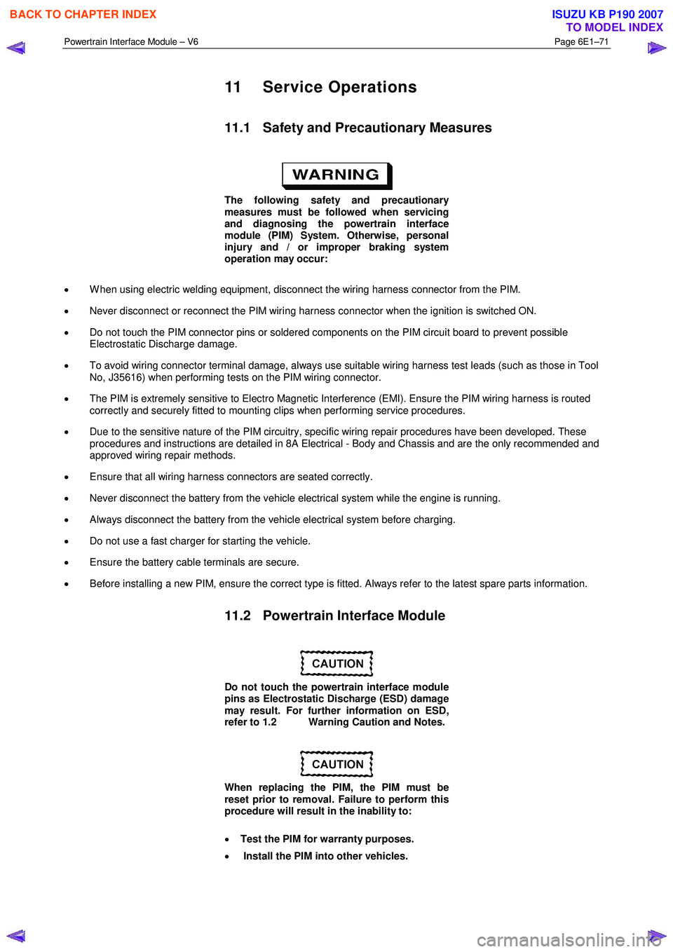
11.1 Safety and Precautionary Measures
The following safety and precautionary
measures must be followed when servicing
and diagnosing the powertrain interface
module (PIM) System. Otherwise, personal
injury and / or improper braking system
operation may occur:
• W hen using electric welding equipment, disconnect the wiring harness connector from the PIM.
• Never disconnect or reconnect the PIM wiring harness connector when the ignition is switched ON.
• Do not touch the PIM connector pins or soldered components on the PIM circuit board to prevent possible
Electrostatic Discharge damage.
• To avoid wiring connector terminal damage, always use suitable wiring harness test leads (such as those in Tool
No, J35616) when performing tests on the PIM wiring connector.
• The PIM is extremely sensitive to Electro Magnetic Interference (EMI). Ensure the PIM wiring harness is routed
correctly and securely fitted to mounting clips when performing service procedures.
• Due to the sensitive nature of the PIM circuitry, specific wiring repair procedures have been developed. These
procedures and instructions are detailed in 8A Electrical - Body and Chassis and are the only recommended and
approved wiring repair methods.
• Ensure that all wiring harness connectors are seated correctly.
• Never disconnect the battery from the vehicle electrical system while the engine is running.
• Always disconnect the battery from the vehicle electrical system before charging.
• Do not use a fast charger for starting the vehicle.
• Ensure the battery cable terminals are secure.
• Before installing a new PIM, ensure the correct type is fitted. Always refer to the latest spare parts information.
11.2 Powertrain Interface Module
Do not touch the powertrain interface module
pins as Electrostatic Discharge (ESD) damage
may result. For further information on ESD,
refer to 1.2 Warning Caution and Notes.
When replacing the PIM, the PIM must be
reset prior to removal. Failure to perform this
procedure will result in the inability to:
• Test the PIM for warranty purposes.
• Install the PIM into other vehicles.
BACK TO CHAPTER INDEX
TO MODEL INDEX
ISUZU KB P190 2007
Page 3813 of 6020
Automatic Transmission – 4L60E – Electrical Diagnosis Page 7C2–27
4 Diagnostics
4.1 Introduction
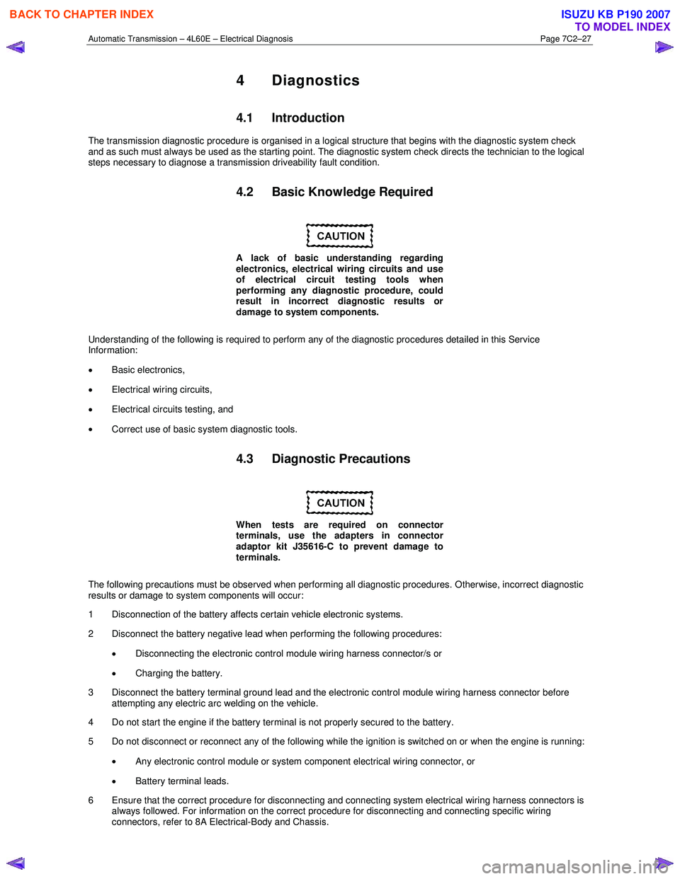
The transmission diagnostic procedure is organised in a logical structure that begins with the diagnostic system check
and as such must always be used as the starting point. The diagnostic system check directs the technician to the logical
steps necessary to diagnose a transmission driveability fault condition.
4.2 Basic Knowledge Required
A lack of basic understanding regarding
electronics, electrical wiring circuits and use
of electrical circuit testing tools when
performing any diagnostic procedure, could
result in incorrect diagnostic results or
damage to system components.
Understanding of the following is required to perform any of the diagnostic procedures detailed in this Service
Information:
• Basic electronics,
• Electrical wiring circuits,
• Electrical circuits testing, and
• Correct use of basic system diagnostic tools.
4.3 Diagnostic Precautions
When tests are required on connector
terminals, use the adapters in connector
adaptor kit J35616-C to prevent damage to
terminals.
The following precautions must be observed when performing all diagnostic procedures. Otherwise, incorrect diagnostic
results or damage to system components will occur:
1 Disconnection of the battery affects certain vehicle electronic systems.
2 Disconnect the battery negative lead when performing the following procedures:
• Disconnecting the electronic control module wiring harness connector/s or
• Charging the battery.
3 Disconnect the battery terminal ground lead and the electronic control module wiring harness connector before attempting any electric arc welding on the vehicle.
4 Do not start the engine if the battery terminal is not properly secured to the battery.
5 Do not disconnect or reconnect any of the following while the ignition is switched on or when the engine is running:
• Any electronic control module or system component electrical wiring connector, or
• Battery terminal leads.
6 Ensure that the correct procedure for disconnecting and connecting system electrical wiring harness connectors is always followed. For information on the correct procedure for disconnecting and connecting specific wiring
connectors, refer to 8A Electrical-Body and Chassis.
BACK TO CHAPTER INDEX
TO MODEL INDEX
ISUZU KB P190 2007
Page 3822 of 6020
Automatic Transmission – 4L60E – Electrical Diagnosis Page 7C2–36
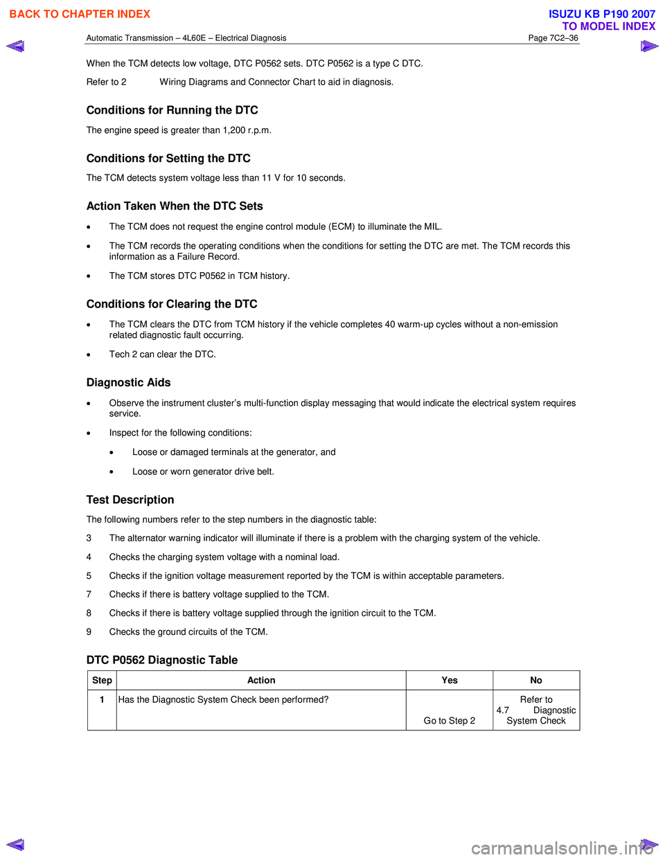
When the TCM detects low voltage, DTC P0562 sets. DTC P0562 is a type C DTC.
Refer to 2 W iring Diagrams and Connector Chart to aid in diagnosis.
Conditions for Running the DTC
The engine speed is greater than 1,200 r.p.m.
Conditions for Setting the DTC
The TCM detects system voltage less than 11 V for 10 seconds.
Action Taken When the DTC Sets
• The TCM does not request the engine control module (ECM) to illuminate the MIL.
• The TCM records the operating conditions when the conditions for setting the DTC are met. The TCM records this
information as a Failure Record.
• The TCM stores DTC P0562 in TCM history.
Conditions for Clearing the DTC
• The TCM clears the DTC from TCM history if the vehicle completes 40 warm-up cycles without a non-emission
related diagnostic fault occurring.
• Tech 2 can clear the DTC.
Diagnostic Aids
• Observe the instrument cluster’s multi-function display messaging that would indicate the electrical system requires
service.
• Inspect for the following conditions:
• Loose or damaged terminals at the generator, and
• Loose or worn generator drive belt.
Test Description
The following numbers refer to the step numbers in the diagnostic table:
3 The alternator warning indicator will illuminate if there is a problem with the charging system of the vehicle.
4 Checks the charging system voltage with a nominal load.
5 Checks if the ignition voltage measurement reported by the TCM is within acceptable parameters.
7 Checks if there is battery voltage supplied to the TCM.
8 Checks if there is battery voltage supplied through the ignition circuit to the TCM.
9 Checks the ground circuits of the TCM.
DTC P0562 Diagnostic Table
Step Action Yes No
1 Has the Diagnostic System Check been performed?
Go to Step 2 Refer to
4.7 Diagnostic
System Check
BACK TO CHAPTER INDEX
TO MODEL INDEX
ISUZU KB P190 2007
Page 3823 of 6020
Automatic Transmission – 4L60E – Electrical Diagnosis Page 7C2–37
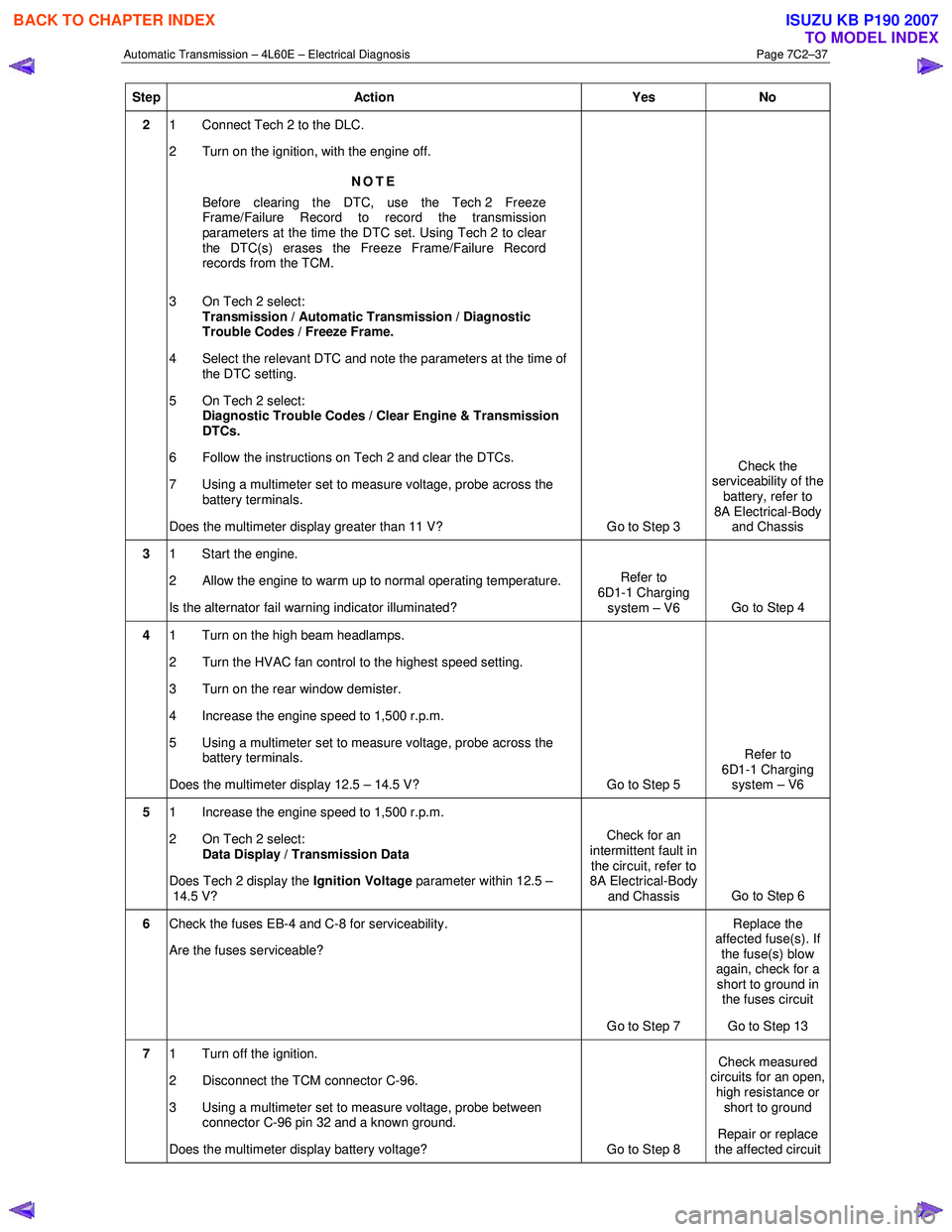
Step Action Yes No
2 1 Connect Tech 2 to the DLC.
2 Turn on the ignition, with the engine off.
NOTE
Before clearing the DTC, use the Tech 2 Freeze
Frame/Failure Record to record the transmission
parameters at the time the DTC set. Using Tech 2 to clear
the DTC(s) erases the Freeze Frame/Failure Record
records from the TCM.
3 On Tech 2 select: Transmission / Automatic Transmission / Diagnostic
Trouble Codes / Freeze Frame.
4 Select the relevant DTC and note the parameters at the time of the DTC setting.
5 On Tech 2 select:
Diagnostic Trouble Codes / Clear Engine & Transmission
DTCs.
6 Follow the instructions on Tech 2 and clear the DTCs.
7 Using a multimeter set to measure voltage, probe across the battery terminals.
Does the multimeter display greater than 11 V? Go to Step 3 Check the
serviceability of the battery, refer to
8A Electrical-Body and Chassis
3 1 Start the engine.
2 Allow the engine to warm up to normal operating temperature.
Is the alternator fail warning indicator illuminated? Refer to
6D1-1 Charging system – V6 Go to Step 4
4 1 Turn on the high beam headlamps.
2 Turn the HVAC fan control to the highest speed setting.
3 Turn on the rear window demister.
4 Increase the engine speed to 1,500 r.p.m.
5 Using a multimeter set to measure voltage, probe across the battery terminals.
Does the multimeter display 12.5 – 14.5 V? Go to Step 5 Refer to
6D1-1 Charging system – V6
5 1 Increase the engine speed to 1,500 r.p.m.
2 On Tech 2 select: Data Display / Transmission Data
Does Tech 2 display the Ignition Voltage parameter within 12.5 –
14.5 V? Check for an
intermittent fault in the circuit, refer to
8A Electrical-Body
and Chassis Go to Step 6
6
Check the fuses EB-4 and C-8 for serviceability.
Are the fuses serviceable?
Go to Step 7 Replace the
affected fuse(s). If the fuse(s) blow
again, check for a short to ground in the fuses circuit
Go to Step 13
7 1 Turn off the ignition.
2 Disconnect the TCM connector C-96.
3 Using a multimeter set to measure voltage, probe between connector C-96 pin 32 and a known ground.
Does the multimeter display battery voltage? Go to Step 8 Check measured
circuits for an open,
high resistance or short to ground
Repair or replace
the affected circuit
BACK TO CHAPTER INDEX
TO MODEL INDEX
ISUZU KB P190 2007