2007 ISUZU KB P190 charging
[x] Cancel search: chargingPage 3825 of 6020
Automatic Transmission – 4L60E – Electrical Diagnosis Page 7C2–39
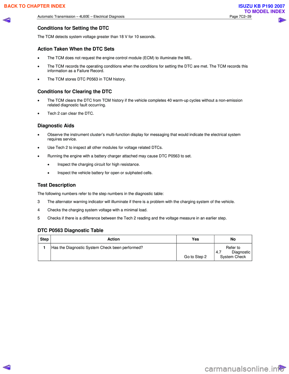
Conditions for Setting the DTC
The TCM detects system voltage greater than 18 V for 10 seconds.
Action Taken When the DTC Sets
•
The TCM does not request the engine control module (ECM) to illuminate the MIL.
• The TCM records the operating conditions when the conditions for setting the DTC are met. The TCM records this
information as a Failure Record.
• The TCM stores DTC P0563 in TCM history.
Conditions for Clearing the DTC
•
The TCM clears the DTC from TCM history if the vehicle completes 40 warm-up cycles without a non-emission
related diagnostic fault occurring.
• Tech 2 can clear the DTC.
Diagnostic Aids
• Observe the instrument cluster’s multi-function display for messaging that would indicate the electrical system
requires service.
• Use Tech 2 to inspect all other modules for voltage related DTCs.
• Running the engine with a battery charger attached may cause DTC P0563 to set.
• Inspect the charging circuit for high resistance.
• Inspect the vehicle battery for open or sulphated cells.
Test Description
The following numbers refer to the step numbers in the diagnostic table:
3 The alternator warning indicator will illuminate if there is a problem with the charging system of the vehicle.
4 Checks the charging system voltage with a minimal load.
5 Checks if there is a difference between the Tech 2 reading and the voltage measure in an earlier step.
DTC P0563 Diagnostic Table
Step Action Yes No
1 Has the Diagnostic System Check been performed?
Go to Step 2 Refer to
4.7 Diagnostic System Check
BACK TO CHAPTER INDEX
TO MODEL INDEX
ISUZU KB P190 2007
Page 3826 of 6020
Automatic Transmission – 4L60E – Electrical Diagnosis Page 7C2–40
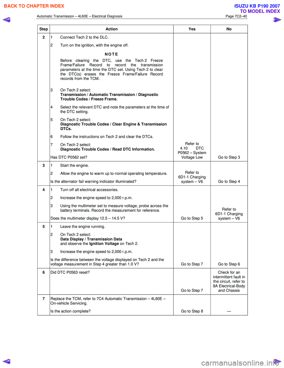
Step Action Yes No
2 1 Connect Tech 2 to the DLC.
2 Turn on the ignition, with the engine off.
NOTE
Before clearing the DTC, use the Tech 2 Freeze
Frame/Failure Record to record the transmission
parameters at the time the DTC set. Using Tech 2 to clear
the DTC(s) erases the Freeze Frame/Failure Record
records from the TCM.
3 On Tech 2 select: Transmission / Automatic Transmission / Diagnostic
Trouble Codes / Freeze Frame.
4 Select the relevant DTC and note the parameters at the time of the DTC setting.
5 On Tech 2 select:
Diagnostic Trouble Codes / Clear Engine & Transmission
DTCs.
6 Follow the instructions on Tech 2 and clear the DTCs.
7 On Tech 2 select: Diagnostic Trouble Codes / Read DTC Information.
Has DTC P0562 set? Refer to
4.10 DTC
P0562 – System
Voltage Low Go to Step 3
3 1 Start the engine.
2 Allow the engine to warm up to normal operating temperature.
Is the alternator fail warning indicator illuminated? Refer to
6D1-1 Charging system – V6 Go to Step 4
4 1 Turn off all electrical accessories.
2 Increase the engine speed to 2,000 r.p.m.
3 Using the multimeter set to measure voltage, probe across the battery terminals. Record the measurement for reference.
Does the multimeter display 12.5 – 14.5 V? Go to Step 5 Refer to
6D1-1 Charging system – V6
5 1 Leave the engine running.
2 On Tech 2 select: Data Display / Transmission Data
and observe the Ignition Voltage on Tech 2.
3 Increase the engine speed to 2,000 r.p.m.
Is the difference between the voltage displayed on Tech 2 and the
voltage measurement in Step 4 greater than 1.0 V? Go to Step 7 Go to Step 6
6 Did DTC P0563 reset?
Go to Step 7 Check for an
intermittent fault in the circuit, refer to
8A Electrical-Body and Chassis
7 Replace the TCM, refer to 7C4 Automatic Transmission – 4L60E –
On-vehicle Servicing.
Is the action complete? Go to Step 8 —
BACK TO CHAPTER INDEX
TO MODEL INDEX
ISUZU KB P190 2007
Page 4002 of 6020
7A2-36 TRANSMISSION CONTROL SYSTEM (AW30–40LE)
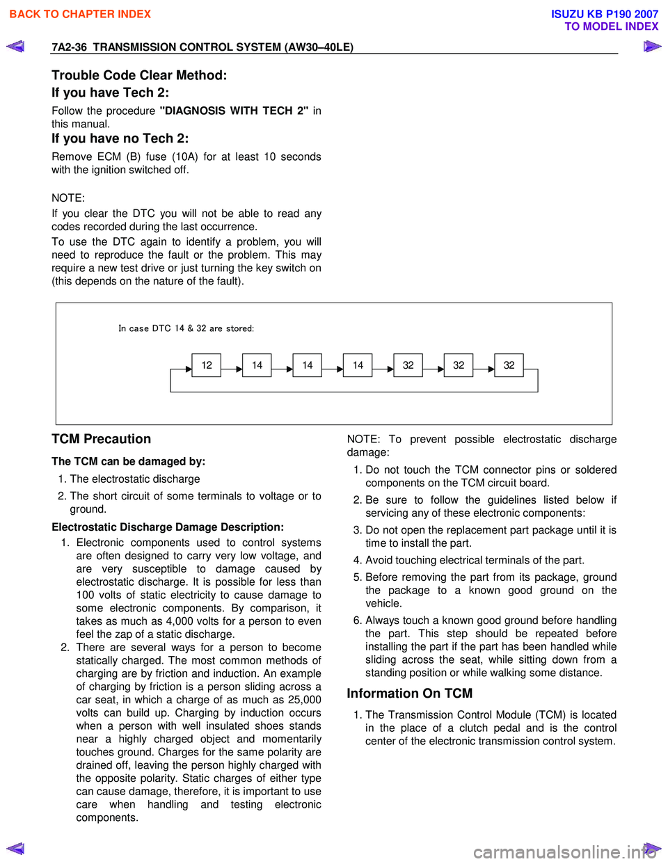
Trouble Code Clear Method:
If you have Tech 2:
Follow the procedure "DIAGNOSIS WITH TECH 2" in
this manual.
If you have no Tech 2:
Remove ECM (B) fuse (10A) for at least 10 seconds
with the ignition switched off.
NOTE:
If you clear the DTC you will not be able to read an
y
codes recorded during the last occurrence.
To use the DTC again to identify a problem, you will
need to reproduce the fault or the problem. This ma
y
require a new test drive or just turning the key switch on
(this depends on the nature of the fault).
12141414323232
In case DTC 14 & 32 are stored:
TCM Precaution
The TCM can be damaged by:
1. The electrostatic discharge
2. The short circuit of some terminals to voltage or to
ground.
Electrostatic Discharge Damage Description: 1. Electronic components used to control systems are often designed to carry very low voltage, and
are very susceptible to damage caused b
y
electrostatic discharge. It is possible for less than
100 volts of static electricity to cause damage to
some electronic components. By comparison, it
takes as much as 4,000 volts for a person to even
feel the zap of a static discharge.
2. There are several ways for a person to become statically charged. The most common methods o
f
charging are by friction and induction. An example
of charging by friction is a person sliding across a
car seat, in which a charge of as much as 25,000
volts can build up. Charging by induction occurs
when a person with well insulated shoes stands
near a highly charged object and momentaril
y
touches ground. Charges for the same polarity are
drained off, leaving the person highly charged with
the opposite polarity. Static charges of either type
can cause damage, therefore, it is important to use
care when handling and testing electronic
components.
NOTE: To prevent possible electrostatic discharge
damage:
1. Do not touch the TCM connector pins or soldered
components on the TCM circuit board.
2. Be sure to follow the guidelines listed below i
f
servicing any of these electronic components:
3. Do not open the replacement part package until it is time to install the part.
4. Avoid touching electrical terminals of the part.
5. Before removing the part from its package, ground
the package to a known good ground on the
vehicle.
6.
Always touch a known good ground before handling
the part. This step should be repeated before
installing the part if the part has been handled while
sliding across the seat, while sitting down from a
standing position or while walking some distance.
Information On TCM
1. The Transmission Control Module (TCM) is located
in the place of a clutch pedal and is the control
center of the electronic transmission control system.
BACK TO CHAPTER INDEX
TO MODEL INDEX
ISUZU KB P190 2007
Page 4007 of 6020
TRANSMISSION CONTROL SYSTEM (AW30–40LE) 7A2-41
• All of the following conditions are met.
- Device Control is not operating
- Disable Normal Communication Service is receiving enable
- DTC Clear is not operating
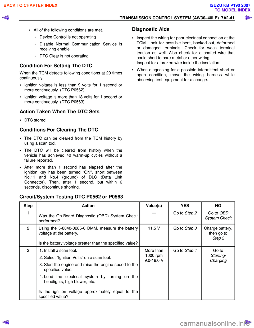
Condition For Setting The DTC
W hen the TCM detects following conditions at 20 times
continuously.
• Ignition voltage is less than 9 volts for 1 second o
r
more continuously. (DTC P0562)
• Ignition voltage is more than 18 volts for 1 second o
r
more continuously. (DTC P0563)
Action Taken When The DTC Sets
• DTC stored.
Conditions For Clearing The DTC
• The DTC can be cleared from the TCM history by
using a scan tool.
• The DTC will be cleared from history when the
vehicle has achieved 40 warm-up cycles without a
failure reported.
•
After more than 1 second has elapsed after the
ignition key has been turned “ON”, short between
No.11 and No.4 (ground) of DLC (Data Link
Connector). Then, after 1 second, but within 6
seconds, discontinue shorting.
Diagnostic Aids
•
Inspect the wiring for poor electrical connection at the
TCM. Look for possible bent, backed out, deformed
or damaged terminals. Check for weak terminal
tension as well. Also check for a chafed wire that
could short to bare metal or other wiring.
Inspect for a broken wire inside the insulation.
• W hen diagnosing for a possible intermittent short o
r
open condition, move the wiring harness while
observing test equipment for a change.
Circuit/System Testing DTC P0562 or P0563
Step Action Value(s) YES NO
1
W as the On-Board Diagnostic (OBD) System Check
performed? — Go to
Step 2 Go to OBD
System Check
2 Using the 5-8840-0285-0 DMM, measure the battery voltage at the battery.
Is the battery voltage greater than the specified value? 11.5 V Go to
Step 3 Charge battery,
then go to Step 3
3 1. Install a scan tool.
2. Select “Ignition Volts” on a scan tool.
3. Start the engine and raise the engine speed to the specified value.
4. Load the electrical system by turning on the headlights, high blower, etc.
Is the ignition voltage approximately equal to the
specified value? More than
1000 rpm
9.0-18.0 V Go to
Step 4 Go to
Starting/
Charging
BACK TO CHAPTER INDEX
TO MODEL INDEX
ISUZU KB P190 2007
Page 4317 of 6020
TRANSMISSION CONTROL SYSTEM (JR405E) 7A2-33
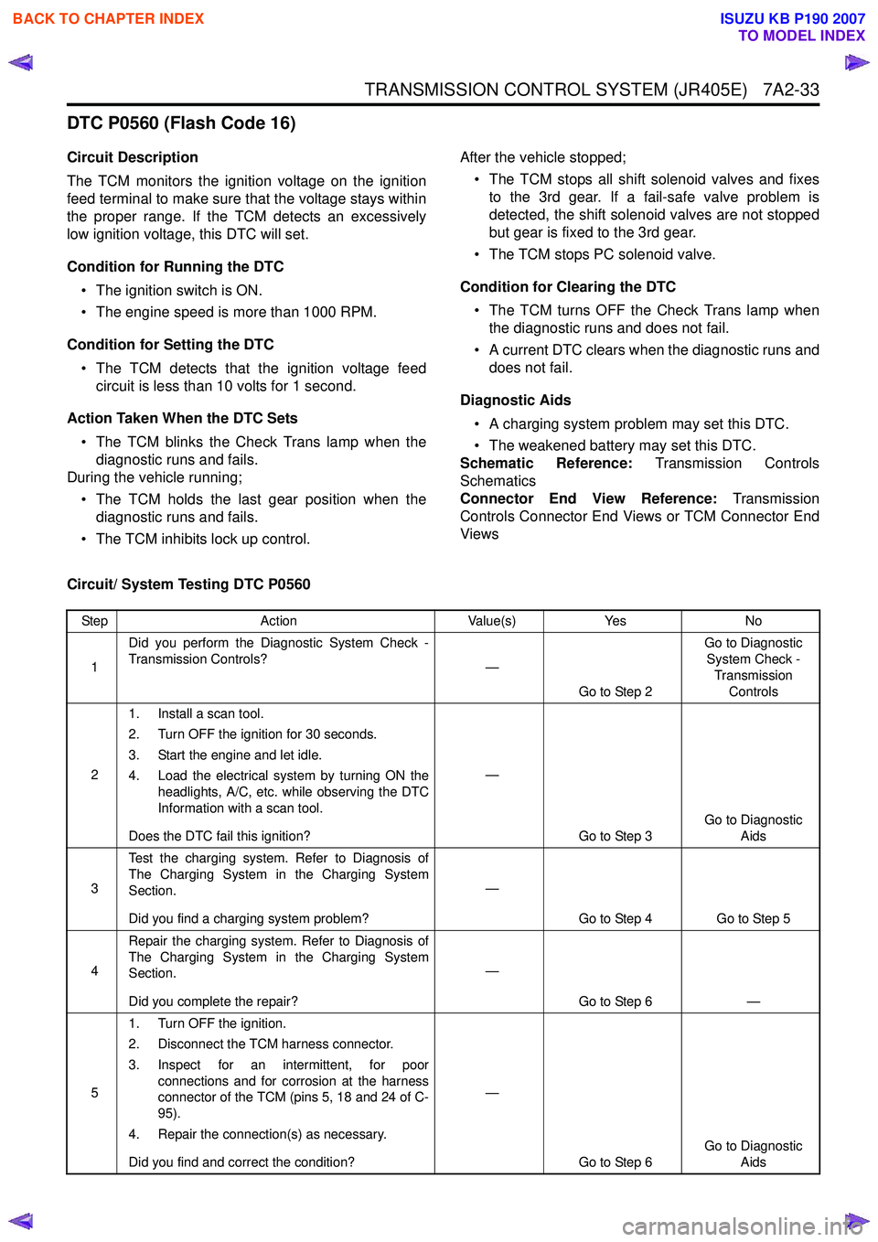
DTC P0560 (Flash Code 16)
Circuit Description
The TCM monitors the ignition voltage on the ignition
feed terminal to make sure that the voltage stays within
the proper range. If the TCM detects an excessively
low ignition voltage, this DTC will set.
Condition for Running the DTC • The ignition switch is ON.
• The engine speed is more than 1000 RPM.
Condition for Setting the DTC • The TCM detects that the ignition voltage feed circuit is less than 10 volts for 1 second.
Action Taken When the DTC Sets • The TCM blinks the Check Trans lamp when the diagnostic runs and fails.
During the vehicle running;
• The TCM holds the last gear position when the diagnostic runs and fails.
• The TCM inhibits lock up control. After the vehicle stopped;
• The TCM stops all shift solenoid valves and fixes to the 3rd gear. If a fail-safe valve problem is
detected, the shift solenoid valves are not stopped
but gear is fixed to the 3rd gear.
• The TCM stops PC solenoid valve.
Condition for Clearing the DTC • The TCM turns OFF the Check Trans lamp when the diagnostic runs and does not fail.
• A current DTC clears when the diagnostic runs and does not fail.
Diagnostic Aids • A charging system problem may set this DTC.
• The weakened battery may set this DTC.
Schematic Reference: Transmission Controls
Schematics
Connector End View Reference: Transmission
Controls Connector End Views or TCM Connector End
Views
Circuit/ System Testing DTC P0560
Step Action Value(s)Yes No
1 Did you perform the Diagnostic System Check -
Transmission Controls? —
Go to Step 2 Go to Diagnostic
System Check -
Transmission Controls
2 1. Install a scan tool.
2. Turn OFF the ignition for 30 seconds.
3. Start the engine and let idle.
4. Load the electrical system by turning ON the headlights, A/C, etc. while observing the DTC
Information with a scan tool.
Does the DTC fail this ignition? —
Go to Step 3 Go to Diagnostic
Aids
3 Test the charging system. Refer to Diagnosis of
The Charging System in the Charging System
Section.
Did you find a charging system problem? —
Go to Step 4 Go to Step 5
4 Repair the charging system. Refer to Diagnosis of
The Charging System in the Charging System
Section.
Did you complete the repair? —
Go to Step 6 —
5 1. Turn OFF the ignition.
2. Disconnect the TCM harness connector.
3. Inspect for an intermittent, for poor connections and for corrosion at the harness
connector of the TCM (pins 5, 18 and 24 of C-
95).
4. Repair the connection(s) as necessary.
Did you find and correct the condition? —
Go to Step 6 Go to Diagnostic
Aids
BACK TO CHAPTER INDEX
TO MODEL INDEX
ISUZU KB P190 2007
Page 4424 of 6020
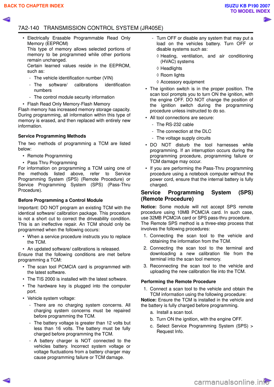
7A2-140 TRANSMISSION CONTROL SYSTEM (JR405E)
• Electrically Erasable Programmable Read OnlyMemory (EEPROM)
This type of memory allows selected portions of
memory to be programmed while other portions
remain unchanged.
Certain learned values reside in the EEPROM,
such as:
- The vehicle identification number (VIN)
- The software/ calibrations identification numbers
- The control module security information
• Flash Read Only Memory-Flash Memory
Flash memory has increased memory storage capacity.
During programming, all information within this type of
memory is erased, and then replaced with entirely new
information.
Service Programming Methods
The two methods of programming a TCM are listed
below:
• Remote Programming
• Pass Thru Programming
For information on programming a TCM using one of
the methods listed above, refer to Service
Programming System (SPS) (Remote Procedure) or
Service Programming System (SPS) (Pass-Thru
Procedure).
Before Programming a Control Module
Important: DO NOT program an existing TCM with the
identical software/ calibration package. This procedure
is not a short cut to correct the driveability condition.
This is an ineffective repair. An TCM should only be
programmed when the following occurs:
• When a service procedure instructs you to replace the TCM.
• An updated software/ calibrations is released.
Ensure that the following conditions are met before
programming a TCM:
• The scan tool PCMCIA card is programmed with the latest software.
• The TIS 2000 is installed with the latest software.
• The hardware key is plugged into the computer port.
• Vehicle system voltage:
- There are no charging system concerns. Allcharging system concerns must be repaired
before programming the TCM.
- The battery voltage is greater than 12 volts but less than 16 volts. The battery must be fully
charged before programming the TCM.
- A battery charger is NOT connected to the vehicles battery. Incorrect system voltage or
voltage fluctuations from a battery charger may
cause programming failure or TCM damage. - Turn OFF or disable any system that may put a
load on the vehicles battery. Turn OFF or
disable systems such as:
◊ Heating, ventilation, and air conditioning
(HVAC) systems
◊ Headlights
◊ Room lights
◊ Accessory equipment
• The ignition switch is in the proper position. The scan tool prompts you to turn ON the ignition, with
the engine OFF. DO NOT change the position of
the ignition switch during the programming
procedure unless instructed to do so.
• All tool connections are secure:
- The RS-232 cable
- The connection at the DLC
- The voltage supply circuits
• DO NOT disturb the tool harnesses while programming. If an interruption occurs during the
programming procedure, programming failure or
TCM damage may occur.
• If you are performing the Pass-Thru programming procedure using a notebook computer without the
power cord, ensure that the internal battery is fully
charged.
Service Programming System (SPS)
(Remote Procedure)
Notice: Some module will not accept SPS remote
procedure using 10MB PCMCIA card. In such case,
use 32MB PCMCIA card or SPS pass-thru procedure.
The Remote SPS method is a three-step process that
involves the following procedures:
1. Connecting the scan tool to the vehicle and obtaining the information from the TCM.
2. Connecting the scan tool to the terminal and downloading a new calibration file from the
terminal into the scan tool memory.
3. Reconnecting the scan tool to the vehicle and uploading the new calibration file into the TCM.
Performing the Remote Procedure 1. Connect a scan tool to the vehicle and obtain the TCM information using the following procedure:
Notice: Ensure the TCM is installed in the vehicle and
the battery is fully charged before programming.
a. Install a scan tool.
b. Turn ON the ignition, with the engine OFF.
c. Select Service Programming System (SPS) > Request Info.
BACK TO CHAPTER INDEX
TO MODEL INDEX
ISUZU KB P190 2007
Page 4437 of 6020
TRANSMISSION CONTROL SYSTEM (JR405E) 7A2-153
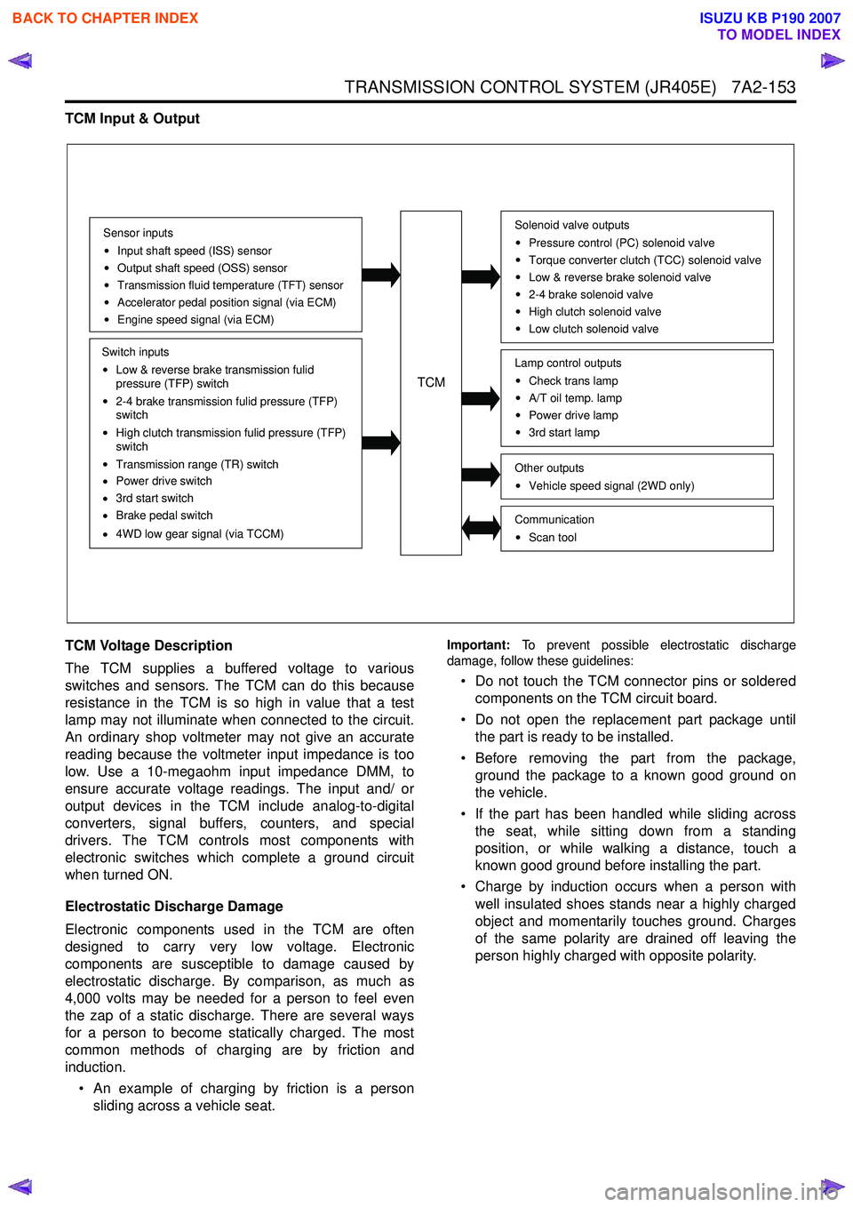
TCM Input & Output
TCM Voltage Description
The TCM supplies a buffered voltage to various
switches and sensors. The TCM can do this because
resistance in the TCM is so high in value that a test
lamp may not illuminate when connected to the circuit.
An ordinary shop voltmeter may not give an accurate
reading because the voltmeter input impedance is too
low. Use a 10-megaohm input impedance DMM, to
ensure accurate voltage readings. The input and/ or
output devices in the TCM include analog-to-digital
converters, signal buffers, counters, and special
drivers. The TCM controls most components with
electronic switches which complete a ground circuit
when turned ON.
Electrostatic Discharge Damage
Electronic components used in the TCM are often
designed to carry very low voltage. Electronic
components are susceptible to damage caused by
electrostatic discharge. By comparison, as much as
4,000 volts may be needed for a person to feel even
the zap of a static discharge. There are several ways
for a person to become statically charged. The most
common methods of charging are by friction and
induction.
• An example of charging by friction is a person sliding across a vehicle seat.
Important: To prevent possible electrostatic discharge
damage, follow these guidelines:
• Do not touch the TCM connector pins or soldered components on the TCM circuit board.
• Do not open the replacement part package until the part is ready to be installed.
• Before removing the part from the package, ground the package to a known good ground on
the vehicle.
• If the part has been handled while sliding across the seat, while sitting down from a standing
position, or while walking a distance, touch a
known good ground before installing the part.
• Charge by induction occurs when a person with well insulated shoes stands near a highly charged
object and momentarily touches ground. Charges
of the same polarity are drained off leaving the
person highly charged with opposite polarity.
Sensor inputs
Input shaft speed (ISS) sensor
Output shaft speed (OSS) sensor
Transmission fluid temperature (TFT) sensor
Accelerator pedal position signal (via ECM)
Engine speed signal (via ECM)
Switch inputs
Low & reverse brake transmission fulid
pressure (TFP) switch
2-4 brake transmission fulid pressure (TFP)
switch
High clutch transmission fulid pressure (TFP)
switch
Transmission range (TR) switch
Power drive switch
3rd start switch
Brake pedal switch
4WD low gear signal (via TCCM)
TCM
Solenoid valve outputs
Pressure control (PC) solenoid valve
Torque converter clutch (TCC) solenoid valve
Low & reverse brake solenoid valve
2-4 brake solenoid valve
High clutch solenoid valve
Low clutch solenoid valve
Other outputsVehicle speed signal (2WD only)
CommunicationScan tool
Lamp control outputsCheck trans lamp
A/T oil temp. lamp
Power drive lamp
3rd start lamp
BACK TO CHAPTER INDEX
TO MODEL INDEX
ISUZU KB P190 2007
Page 4940 of 6020
8A-2 ELECTRICAL-BODY AND CHASSIS
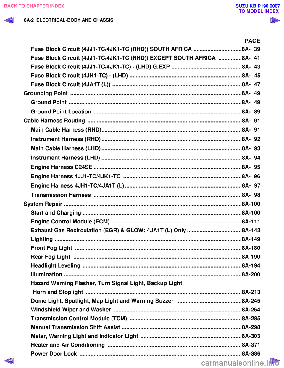
PAGE
Fuse Block Circuit (4JJ1-TC/4JK1-TC (RHD)) SOUTH AFRICA ...............................8A- 39
Fuse Block Circuit (4JJ1-TC/4JK1-TC (RHD)) EXCEPT SOUTH AFRICA ...............8A- 41
Fuse Block Circuit (4JJ1-TC/4JK1-TC) - (LHD) G.EXP .............................................8A- 43
Fuse Block Circuit (4JH1-TC) - (LHD) ........................................................................8A- 45
Fuse Block Circuit (4JA1T (L)) ...................................................................................8A- 47
Grounding Point ..............................................................................................................8 A- 49
Ground Point ...............................................................................................................8A- 49
Ground Point Location ...............................................................................................8A- 89
Cable Harness Routing ...................................................................................................8A- 91
Main Cable Harness (RHD)..........................................................................................8A- 91
Instrument Harness (RHD) ..........................................................................................8A- 92
Main Cable Harness (LHD) ..........................................................................................8A- 93
Instrument Harness (LHD) ..........................................................................................8A- 94
Engine Harness C24SE ...............................................................................................8A- 95
Engine Harness 4JJ1-TC/4JK1-TC ............................................................................8A- 96
Engine Harness 4JH1-TC/4JA1T (L) ...........................................................................8A- 97
Transmission Harness ...............................................................................................8A- 98
System Repair ................................................................................................................. .8A- 100
Start and Charging ......................................................................................................8A- 10 0
Engine Control Module (ECM) ...................................................................................8A- 111
Exhaust Gas Recirculation (EGR) & GLOW; 4JA1T (L) Only ...................................8A- 143
Lighting ...................................................................................................................... ..8A- 149
Front Fog Light ...........................................................................................................8A- 180
Rear Fog Light ............................................................................................................8A- 190
Headlight Leveling ......................................................................................................8A- 19 4
Illumination .................................................................................................................. 8A- 200
Hazard Warning Flasher, Turn Signal Light, Backup Light, Horn and Stoplight ....................................................................................................8A- 213
Dome Light, Spotlight, Map Light and Warning Buzzer ..........................................8A- 245
Windshield Wiper and Washer ..................................................................................8A- 264
Transmission Control Module (TCM) ........................................................................8A- 285
Manual Transmission Shift Assist .............................................................................8A- 298
Meter, Warning Light and Indicator Light .................................................................8A- 303
Heater and Air Conditioning ......................................................................................8A- 371
Power Door Lock ........................................................................................................8A- 386
BACK TO CHAPTER INDEX
TO MODEL INDEX
ISUZU KB P190 2007