Page 3602 of 6020
Charging System – V6 Page 6D1-1-15
4 Major Service Operations
4.1 Generator
Remove
Refer to 1.2 WARNING, CAUTION and NOTES
before disconnecting the battery.
1 Disconnect the battery ground lead P-5. Refer to 8A Electrical Body and Chassis.
2 Insert a ½ inch drive socket bar into the tensioner arm and rotate the tensioner arm clockwise.
3 Remove the drive belt from the generator pulley and release the tensioner. Refer to 6A1 Engine Mechanical – V6 for further details as required.
4 Pull the battery harness cap back from generator terminal P-9 (3), remove the nut (4) and remove the
positive lead (2) from the generator (5).
5 Disengage the connector retaining clip and remove the connector E-4, (1) from the generator.
Figure 6D1-1 4
6 Remove the three bolts (1, 2, 4) retaining the generator (3) to the generator bracket.
7 Remove the generator assembly from the vehicle.
Figure 6D1-1 5
BACK TO CHAPTER INDEX
TO MODEL INDEX
ISUZU KB P190 2007
Page 3603 of 6020
Charging System – V6 Page 6D1-1-16
Reinstall
Reinstallation of the generator is the reverse of the removal procedure, noting the following:
1 Tighten all fasteners to the correct torque specification.
2 Reconnect the battery ground lead.
3 Start the engine.
4 Check the generator warning indicator operation.
5 Check the drive belt is correctly routed and aligned.
6 Check the generator output. Refer to 3.3 On-vehicle Testing.
7 Check the voltage regulator operation. Refer to 3.3 On-vehicle Testing.
8 Turn the ignition switch off.
Generator mounting bolts ........................... (1) 58.0 Nm
Generator mounting bolts ........................... (2) 58.0 Nm
Generator mounting bolts ........................... (4) 58.0 Nm
Battery harness to P-9 pin B nut
torque specification ...................................7.1 – 13.3 Nm
BACK TO CHAPTER INDEX
TO MODEL INDEX
ISUZU KB P190 2007
Page 3604 of 6020
Charging System – V6 Page 6D1-1-17
4.2 Generator Mounting Bracket
Remove
1 Remove the idler pulley bolt (7) then the idler pulley (6), Refer to 4.1 Generator.
2 Remove the bolts (1, 2, 3 ,4); five places attaching the generator mounting bracket (5) to the engine block.
3 Remove the generator mounting bracket from the vehicle.
Figure 6D1-1 6
Reinstall
Reinstallation of the generator mounting bracket and generator is the reverse of the removal procedure, noting the
following:
1 Tighten all fasteners to the correct torque specification.
2 Reinstall the generator, refer to 4.1 Generator.
Generator mounting bracket bolts ... (1) 40.0 – 60.0 Nm
Generator mounting bracket bolts ... (2) 100.0 Nm
Generator mounting bracket bolts ... (3) 40.0 – 60.0 Nm
Generator mounting bracket bolts ... (4) 40.0 – 60.0 Nm
Idler pulley bolt................................. (7) 58.0 Nm
BACK TO CHAPTER INDEX
TO MODEL INDEX
ISUZU KB P190 2007
Page 3605 of 6020
Charging System – V6 Page 6D1-1-18
4.3 Drive Belt Routing
Without Air Conditioning
Ensure the drive belt ribs are correctly positioned in all pulleys and the crankshaft balancer.
NOTE
For detailed information relating to drive belt
service procedure, refer to 6A1 Engine
Mechanical.
Figure 6D1-1 7 shows the drive belt routing for the HFV6 engine without air-conditioning.
Figure 6D1-1 7
Legend
1 Water Pump
2 Generator
3 Idler 4 Power Steering
5 Crankshaft
6 Tensioner
BACK TO CHAPTER INDEX
TO MODEL INDEX
ISUZU KB P190 2007
Page 3606 of 6020

Charging System – V6 Page 6D1-1-19
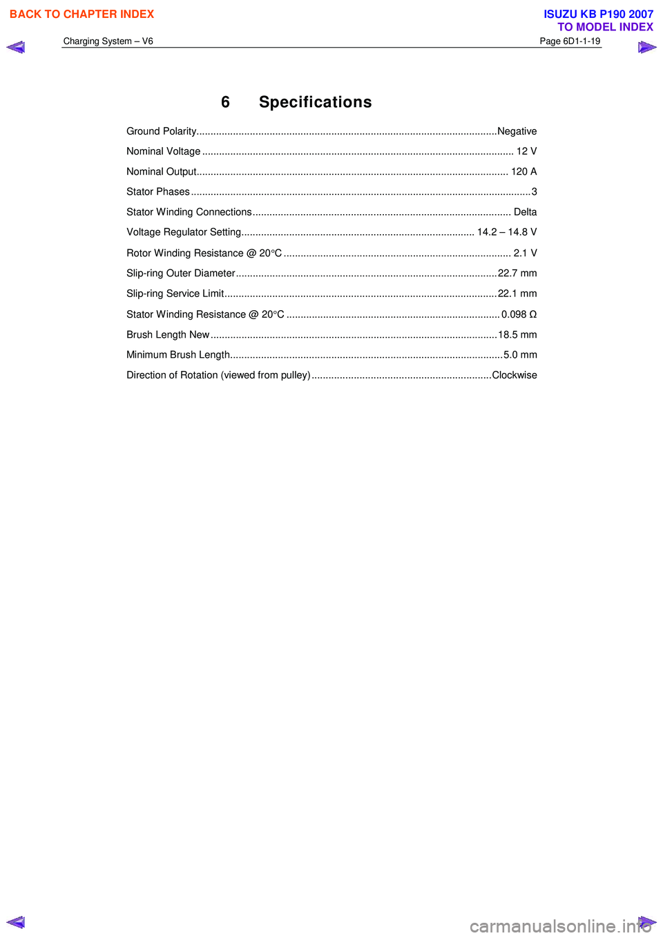
6 Specifications
Ground Polarity...........................................................................................................Negative
Nominal Voltage ............................................................................................................... 1 2 V
Nominal Output............................................................................................................... 12 0 A
Stator Phases .................................................................................................................. ....... 3
Stator W inding Connections ............................................................................................ Delta
Voltage Regulator Setting................................................................................... 14.2 – 14.8 V
Rotor W inding Resistance @ 20 °C ................................................................................. 2.1 V
Slip-ring Outer Diameter ............................................................................................. 22.7 mm
Slip-ring Service Limit ................................................................................................. 22.1 mm
Stator W inding Resistance @ 20 °C ............................................................................ 0.098 Ω
Brush Length New ...................................................................................................... 18.5 mm
Minimum Brush Length................................................................................................. 5.0 mm
Direction of Rotation (viewed from pulley) ................................................................Clockwise
BACK TO CHAPTER INDEX
TO MODEL INDEX
ISUZU KB P190 2007
Page 3607 of 6020
Charging System – V6 Page 6D1-1-20
7 Torque Wrench Specifications
..................................................................................................................... Nm
Generator Mounting Bolts (1, 2, 4) ..............................................................58.0
Generator Mounting Bracket Bolts (1, 3, 4) ......................................40.0 – 60.0
Generator Mounting Bracket Bolts (2) ...........................................................0.0
Battery Harness to G8 – X1 pin A Nut................................................5.0 – 12.0
BACK TO CHAPTER INDEX
TO MODEL INDEX
ISUZU KB P190 2007
Page 3608 of 6020
Charging System – V6 Page 6D1-1-21
8 Special Tools
TOOL NUMBER ILLUSTRATION
DESCRIPTION TOOL
CLASSIFICATION
J35616-A
(KM609)
CONNECTOR TEST ADAPTOR KIT
Used when carrying out electrical
diagnostic circuit checks.
Previously released. Desirable
3588
(J39200)
DIGITAL MULTIMETER
Must have at least 10 M Ω input
impedance and be capable of reading
frequencies.
Previously released. Available
BACK TO CHAPTER INDEX
TO MODEL INDEX
ISUZU KB P190 2007
Page 3646 of 6020

Battery Page 6D1-3–6
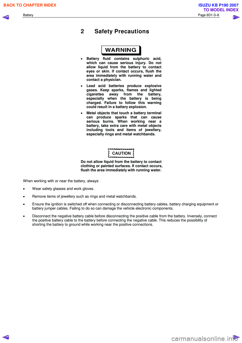
2 Safety Precautions
• Battery fluid contains sulphuric acid,
which can cause serious injury. Do not
allow liquid from the battery to contact
eyes or skin. If contact occurs, flush the
area immediately with running water and
contact a physician.
• Lead acid batteries produce explosive
gases. Keep sparks, flames and lighted
cigarettes away from the battery,
especially when the battery is being
charged. Failure to follow this warning
could result in a battery explosion.
• Metal objects that touch a battery terminal
can produce sparks that can cause
serious burns. When working near a
battery, take extra care with metal objects
including tools and items of jewellery,
especially rings and metal watchbands.
Do not allow liquid from the battery to contact
clothing or painted surfaces. If contact occurs,
flush the area immediately with running water.
W hen working with or near the battery, always:
• W ear safety glasses and work gloves.
• Remove items of jewellery such as rings and metal watchbands.
• Ensure the ignition is switched off when connecting or disconnecting battery cables, battery charging equipment or
battery jumper cables. Failing to do so can damage the vehicle electronic components.
• Disconnect the negative battery cable before disconnecting the positive cable from the battery. Inversely, connect
the positive battery cable to the battery before connecting the negative cable. This reduces the possibility of
shorting the battery to ground while working near the positive connections.
BACK TO CHAPTER INDEX
TO MODEL INDEX
ISUZU KB P190 2007