Page 4952 of 6020
8A-14 ELECTRICAL-BODY AND CHASSIS
Distinction of Circuit by Wire Base Color
Base color Circuits Base color Circuits
B Starter circuit and grounding circuit Y Instrument circuit
W Charging circuit L, O, BR,
R Lighting circuit LG, GR, Other circuits
G Signal circuit P, LB, V
Wire Size
W ire size is specified with the metric gauge system.
The metric gauge system gives the wire size in cross sectional
area measured in square millimeters.
Wire Size Specifications
Nominal size Cross sectional area
(mm2) Outside diameter
(mm) Allowable current
(A)
0.3 0.372 1.8 9
0.5 0.563 2.0 12
0.85 0.885 2.2 16
1.25 1.287 2.5 21
2 2.091 2.9 28
3 3.296 3.6 37.5
5 5.227 4.4 53
8 7.952 5.5 67
15 13.36 7.0 75
20 20.61 8.2 97
BACK TO CHAPTER INDEX TO MODEL INDEXISUZU KB P190 2007
Page 4957 of 6020
ELECTRICAL-BODY AND CHASSIS 8A-19
Battery-1
BATTERY
Inspection
1. Check the battery terminals 1 for corrosion.
2. Check the battery cables
2 for looseness.
3. Check the battery case
3 for cracks and other damage.
4. Check the battery electrolyte level.
Battery-2
Battery Replacement
1. Disconnect the battery ground cable 1.
2. Disconnect the battery positive cable
2.
3. Remove the battery clamp
3.
4. Remove the battery
Caution:
It is important that the battery ground cable be removed
first.
Removing the battery positive cable first can result in a
short circuit.
Jump Starting the Engine with a Booster Battery
The following description assumes that you are using a booster
battery mounted on a second vehicle.
The listed steps (with some minor modifications) are also
applicable if you are using a naked booster battery or special
battery charging equipment.
BACK TO CHAPTER INDEX TO MODEL INDEXISUZU KB P190 2007
Page 5038 of 6020
8A-100 ELECTRICAL-BODY AND CHASSIS
SYSTEM REPAIR
START AND CHARGING
PARTS LOCATION (RHD)
RTW 78AXF036101
BACK TO CHAPTER INDEX
TO MODEL INDEXISUZU KB P190 2007
Page 5577 of 6020

CRUISE CONTROL SYSTEM 8B-5
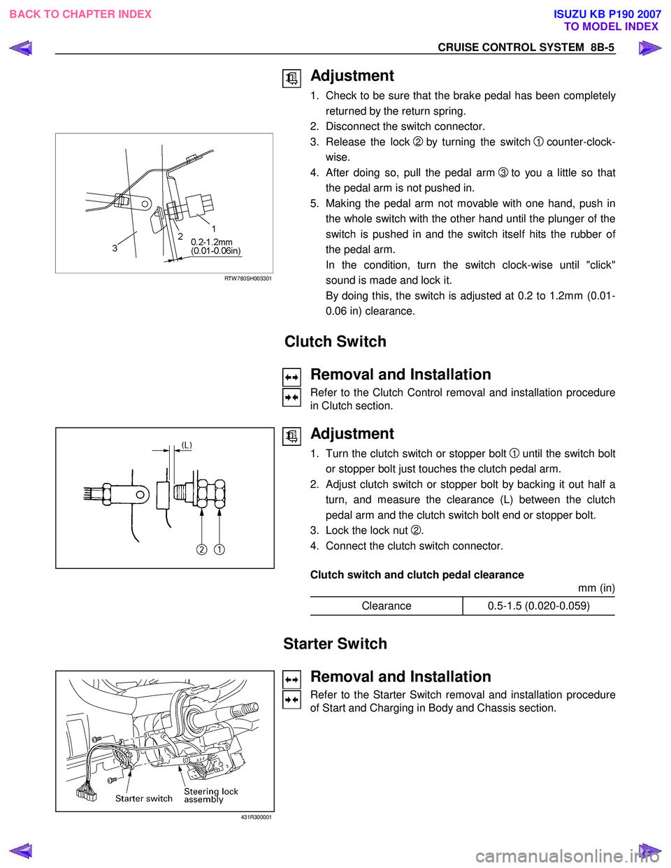
Adjustment
1. Check to be sure that the brake pedal has been completely
returned by the return spring.
2. Disconnect the switch connector.
RTW 780SH003301
3. Release the lock 2 by turning the switch 1 counter-clock-
wise.
4. After doing so, pull the pedal arm
3 to you a little so that
the pedal arm is not pushed in.
5. Making the pedal arm not movable with one hand, push in
the whole switch with the other hand until the plunger of the
switch is pushed in and the switch itself hits the rubber o
f
the pedal arm.
In the condition, turn the switch clock-wise until "click"
sound is made and lock it.
By doing this, the switch is adjusted at 0.2 to 1.2mm (0.01-
0.06 in) clearance.
Clutch Switch
Removal and Installation
Refer to the Clutch Control removal and installation procedure
in Clutch section.
Adjustment
1. Turn the clutch switch or stopper bolt 1 until the switch bolt
or stopper bolt just touches the clutch pedal arm.
2.
Adjust clutch switch or stopper bolt by backing it out half a
turn, and measure the clearance (L) between the clutch
pedal arm and the clutch switch bolt end or stopper bolt.
3. Lock the lock nut
2.
4. Connect the clutch switch connector.
Clutch switch and clutch pedal clearance
mm (in)
Clearance 0.5-1.5 (0.020-0.059)
Starter Switch
431R300001
Removal and Installation
Refer to the Starter Switch removal and installation procedure
of Start and Charging in Body and Chassis section.
BACK TO CHAPTER INDEX
TO MODEL INDEXISUZU KB P190 2007
Page 5754 of 6020
9A1-72 RESTRAINT CONTROL SYSTEM
DTC B0062 (Flash Code 62) Battery Voltage Too High
Step Action Yes No
1 W as the “SRS Diagnostic System Check” performed? Go to Step 2 Go to the “SRS
Diagnostic System Check”
2 1. Ignition switch is at “LOCK”.
2. Disconnect the SRS control unit.
3. Ignition switch “ON”.
4. Measure voltage on SRS control unit harness connector from terminal “1” to terminal “3” (ground).
Is voltage on terminal “1” below 16.5V? Ignition switch is at
“LOCK”.
Replace the SRS control unit.
Go to Step 3 Inspect the
Charging System. Refer to the
"Engine Electrical" section.
Go to Step 3
3 1. Reconnect all the components and ensure all components
are properly mounted.
2. Clear diagnostic trouble codes.
Is this step finished? Go to the “SRS
Diagnostic system Check” ―
BACK TO CHAPTER INDEX
TO MODEL INDEX
ISUZU KB P190 2007
Page 5756 of 6020

9A1-74 RESTRAINT CONTROL SYSTEM
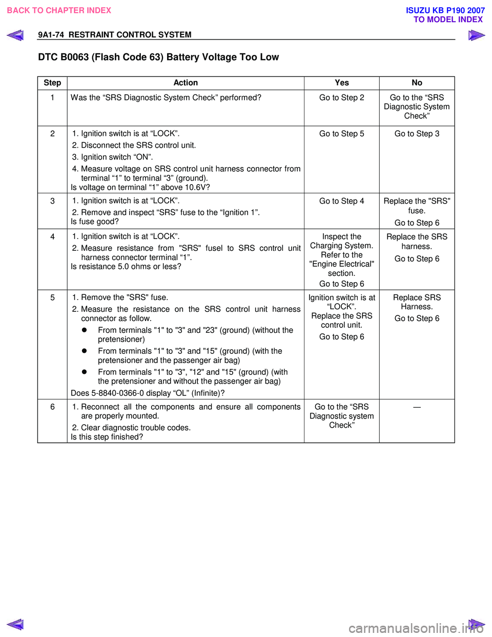
DTC B0063 (Flash Code 63) Battery Voltage Too Low
Step Action Yes No
1 W as the “SRS Diagnostic System Check” performed? Go to Step 2 Go to the “SRS
Diagnostic System Check”
2 1. Ignition switch is at “LOCK”.
2. Disconnect the SRS control unit.
3. Ignition switch “ON”.
4. Measure voltage on SRS control unit harness connector from terminal “1” to terminal “3” (ground).
Is voltage on terminal “1” above 10.6V? Go to Step 5 Go to Step 3
3
1. Ignition switch is at “LOCK”.
2. Remove and inspect “SRS” fuse to the “Ignition 1”.
Is fuse good? Go to Step 4 Replace the "SRS"
fuse.
Go to Step 6
4
1. Ignition switch is at “LOCK”.
2. Measure resistance from "SRS" fusel to SRS control unit
harness connector terminal “1”.
Is resistance 5.0 ohms or less? Inspect the
Charging System. Refer to the
"Engine Electrical" section.
Go to Step 6 Replace the SRS
harness.
Go to Step 6
5
1. Remove the "SRS" fuse.
2. Measure the resistance on the SRS control unit harness connector as follow.
�z From terminals "1" to "3" and "23" (ground) (without the
pretensioner)
�z From terminals "1" to "3" and "15" (ground) (with the
pretensioner and the passenger air bag)
�z From terminals "1" to "3", "12" and "15" (ground) (with
the pretensioner and without the passenger air bag)
Does 5-8840-0366-0 display “OL” (Infinite)? Ignition switch is at
“LOCK”.
Replace the SRS control unit.
Go to Step 6 Replace SRS
Harness.
Go to Step 6
6 1. Reconnect all the components and ensure all components
are properly mounted.
2. Clear diagnostic trouble codes.
Is this step finished? Go to the “SRS
Diagnostic system Check” ―
BACK TO CHAPTER INDEX
TO MODEL INDEX
ISUZU KB P190 2007