2007 ISUZU KB P190 charging
[x] Cancel search: chargingPage 2375 of 6020
ENGINE DRIVEABILITY AND EMISSIONS 6E–205
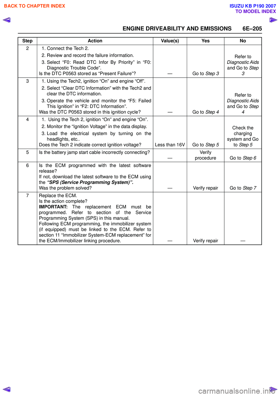
2 1. Connect the Tech 2. 2. Review and record the failure information.
3. Select “F0: Read DTC Infor By Priority” in “F0: Diagnostic Trouble Code”.
Is the DTC P0563 stored as “Present Failure”? — Go to Step 3Refer to
Diagnostic Aids and Go to Step
3
3 1. Using the Tech2, ignition “On” and engine “Off”. 2. Select “Clear DTC Information” with the Tech2 andclear the DTC information.
3. Operate the vehicle and monitor the “F5: Failed This Ignition” in “F2: DTC Information”.
Was the DTC P0563 stored in this ignition cycle? — Go to Step 4Refer to
Diagnostic Aids and Go to Step
4
4 1. Using the Tech 2, ignition “On” and engine “On”. 2. Monitor the “Ignition Voltage” in the data display.
3. Load the electrical system by turning on the headlights, etc..
Does the Tech 2 indicate correct ignition voltage? Less than 16V Go to Step 5Check the
charging
system and Go to Step 5
5 Is the battery jamp start cable incorrectly connecting? —Ve r if y
procedure Go to Step 6
6 Is the ECM programmed with the latest software release?
If not, download the latest software to the ECM using
the “SPS (Service Programming System)”.
Was the problem solved? — Verify repair Go to Step 7
7 Replace the ECM. Is the action complete?
IMPORTANT: The replacement ECM must be
programmed. Refer to section of the Service
Programming System (SPS) in this manual.
Following ECM programming, the immobilizer system
(if equipped) must be linked to the ECM. Refer to
section 11 “Immobilizer System-ECM replacement” for
the ECM/Immobilizer linking procedure. — Verify repair —
Step
Action Value(s) Yes No
BACK TO CHAPTER INDEX
TO MODEL INDEX
ISUZU KB P190 2007
Page 2479 of 6020
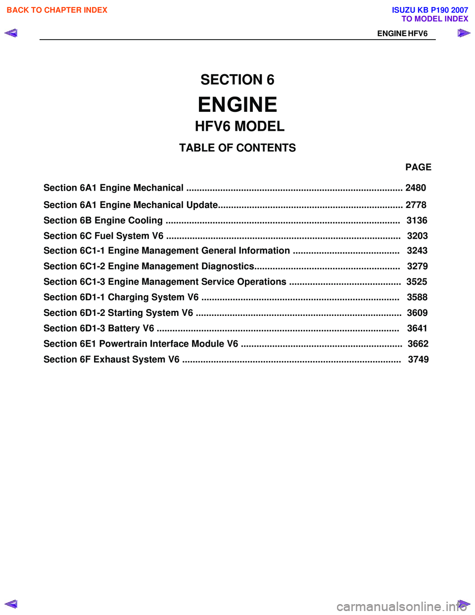
Section 6A1 Engine Mechanical ................................................................................... 2480 PAGE
Section 6A1 Engine Mechanical Update....................................................................... 2778
Section 6C1-1 Engine Management General Information ......................................... 3243
Section 6C1-2 Engine Management Diagnostics........................................................ 3279
Section 6C1-3 Engine Management Service Operations ........................................... 3525
Section 6D1-1 Charging System V6 ............................................................................ 3588
SECTION 6
ENGINE
TA BLE OF CONTENTS
Section 6D1-3 Battery V6 ............................................................................................. 3641
Section 6E1 Powertrain Interface Module V6 .............................................................. 3662
HFV6 MODEL
ENGINE HFV6
Section 6B Engine Cooling .......................................................................................... 3136
Section 6C Fuel System V6 .......................................................................................... 3203
Section 6 D1-2 St art ing Syste m V 6 ............................................................................... 36 09
Section 6F Exhaust System V6 .................................................................................... 3749
BACK TO CHAPTER INDEX
TO MODEL INDEX
ISUZU KB P190 2007
Page 3296 of 6020
Engine Management – V6 – Diagnostics Page 6C1-2–18
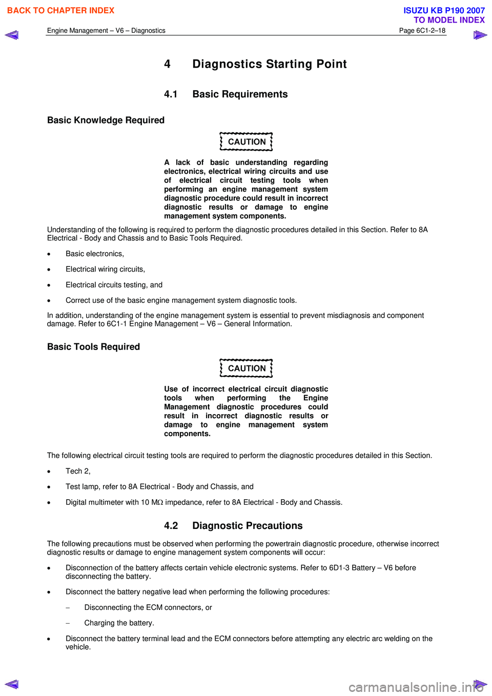
4 Diagnostics Starting Point
4.1 Basic Requirements
Basic Knowledge Required
A lack of basic understanding regarding
electronics, electrical wiring circuits and use
of electrical circuit testing tools when
performing an engine management system
diagnostic procedure could result in incorrect
diagnostic results or damage to engine
management system components.
Understanding of the following is required to perform the diagnostic procedures detailed in this Section. Refer to 8A
Electrical - Body and Chassis and to Basic Tools Required.
• Basic electronics,
• Electrical wiring circuits,
• Electrical circuits testing, and
• Correct use of the basic engine management system diagnostic tools.
In addition, understanding of the engine management system is essential to prevent misdiagnosis and component
damage. Refer to 6C1-1 Engine Management – V6 – General Information.
Basic Tools Required
Use of incorrect electrical circuit diagnostic
tools when performing the Engine
Management diagnostic procedures could
result in incorrect diagnostic results or
damage to engine management system
components.
The following electrical circuit testing tools are required to perform the diagnostic procedures detailed in this Section.
• Tech 2,
• Test lamp, refer to 8A Electrical - Body and Chassis, and
• Digital multimeter with 10 M Ω impedance, refer to 8A Electrical - Body and Chassis.
4.2 Diagnostic Precautions
The following precautions must be observed when performing the powertrain diagnostic procedure, otherwise incorrect
diagnostic results or damage to engine management system components will occur:
• Disconnection of the battery affects certain vehicle electronic systems. Refer to 6D1-3 Battery – V6 before
disconnecting the battery.
• Disconnect the battery negative lead when performing the following procedures:
− Disconnecting the ECM connectors, or
− Charging the battery.
• Disconnect the battery terminal lead and the ECM connectors before attempting any electric arc welding on the
vehicle.
BACK TO CHAPTER INDEX
TO MODEL INDEX
ISUZU KB P190 2007
Page 3309 of 6020
Engine Management – V6 – Diagnostics Page 6C1-2–31
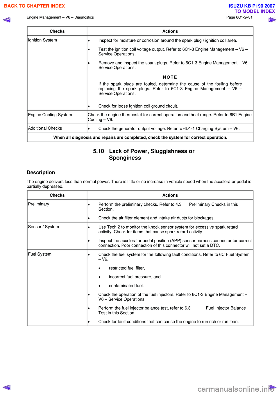
Checks Actions
Ignition System
• Inspect for moisture or corrosion around the spark plug / ignition coil area.
• Test the ignition coil voltage output. Refer to 6C1-3 Engine Management – V6 –
Service Operations.
• Remove and inspect the spark plugs. Refer to 6C1-3 Engine Management – V6 –
Service Operations.
NOTE
If the spark plugs are fouled, determine the cause of the fouling before
replacing the spark plugs. Refer to 6C1-3 Engine Management – V6 –
Service Operations.
• Check for loose ignition coil ground circuit.
Engine Cooling System Check the engine thermostat for correct operation and heat range. Refer to 6B1 Engine
Cooling – V6.
Additional Checks • Check the generator output voltage. Refer to 6D1-1 Charging System – V6.
When all diagnosis and repairs are completed, check the system for correct operation.
5.10 Lack of Power, Sluggishness or
Sponginess
Description
The engine delivers less than normal power. There is little or no increase in vehicle speed when the accelerator pedal is
partially depressed.
Checks Actions
Preliminary • Perform the preliminary checks. Refer to 4.3 Preliminary Checks in this
Section.
• Check the air filter element and intake air ducts for blockages.
Sensor / System
• Use Tech 2 to monitor the knock sensor system for excessive spark retard
activity. Check for items that cause spark retard activity.
• Inspect the accelerator pedal position (APP) sensor harness connector for correct
connection. Poor connection of this connector will not set a DTC.
Fuel System • Check the fuel system for the following fault conditions. Refer to 6C Fuel System
– V6.
• restricted fuel filter,
• incorrect fuel pressure, and
• contaminated fuel.
• Check the operation of the fuel injectors. Refer to 6C1-3 Engine Management –
V6 – Service Operations.
• Perform the fuel injector balance test, refer to 6.3 Fuel Injector Balance
Test in this Section.
• Check for fault conditions that can cause the engine to run rich or run lean.
BACK TO CHAPTER INDEX
TO MODEL INDEX
ISUZU KB P190 2007
Page 3426 of 6020
Engine Management – V6 – Diagnostics Page 6C1-2–148
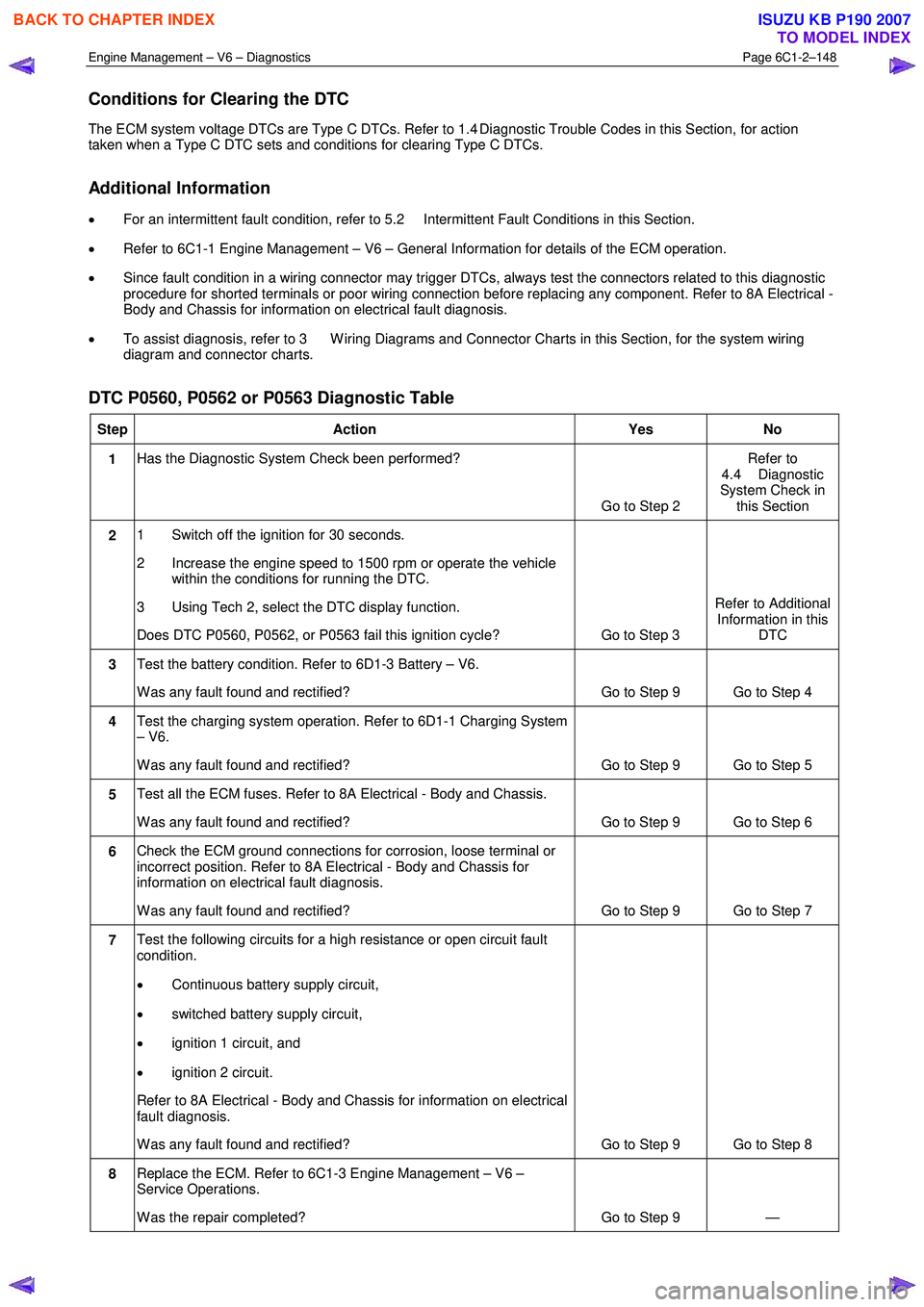
Conditions for Clearing the DTC
The ECM system voltage DTCs are Type C DTCs. Refer to 1.4 Diagnostic Trouble Codes in this Section, for action
taken when a Type C DTC sets and conditions for clearing Type C DTCs.
Additional Information
• For an intermittent fault condition, refer to 5.2 Intermittent Fault Conditions in this Section.
• Refer to 6C1-1 Engine Management – V6 – General Information for details of the ECM operation.
• Since fault condition in a wiring connector may trigger DTCs, always test the connectors related to this diagnostic
procedure for shorted terminals or poor wiring connection before replacing any component. Refer to 8A Electrical -
Body and Chassis for information on electrical fault diagnosis.
• To assist diagnosis, refer to 3 W iring Diagrams and Connector Charts in this Section, for the system wiring
diagram and connector charts.
DTC P0560, P0562 or P0563 Diagnostic Table
Step Action Yes No
1 Has the Diagnostic System Check been performed?
Go to Step 2 Refer to
4.4 Diagnostic
System Check in this Section
2 1 Switch off the ignition for 30 seconds.
2 Increase the engine speed to 1500 rpm or operate the vehicle within the conditions for running the DTC.
3 Using Tech 2, select the DTC display function.
Does DTC P0560, P0562, or P0563 fail this ignition cycle? Go to Step 3 Refer to Additional
Information in this DTC
3 Test the battery condition. Refer to 6D1-3 Battery – V6.
W as any fault found and rectified? Go to Step 9 Go to Step 4
4 Test the charging system operation. Refer to 6D1-1 Charging System
– V6.
W as any fault found and rectified? Go to Step 9 Go to Step 5
5 Test all the ECM fuses. Refer to 8A Electrical - Body and Chassis.
W as any fault found and rectified? Go to Step 9 Go to Step 6
6 Check the ECM ground connections for corrosion, loose terminal or
incorrect position. Refer to 8A Electrical - Body and Chassis for
information on electrical fault diagnosis.
W as any fault found and rectified? Go to Step 9 Go to Step 7
7 Test the following circuits for a high resistance or open circuit fault
condition.
• Continuous battery supply circuit,
• switched battery supply circuit,
• ignition 1 circuit, and
• ignition 2 circuit.
Refer to 8A Electrical - Body and Chassis for information on electrical
fault diagnosis.
W as any fault found and rectified? Go to Step 9 Go to Step 8
8 Replace the ECM. Refer to 6C1-3 Engine Management – V6 –
Service Operations.
W as the repair completed? Go to Step 9 —
BACK TO CHAPTER INDEX
TO MODEL INDEX
ISUZU KB P190 2007
Page 3431 of 6020
Engine Management – V6 – Diagnostics Page 6C1-2–153
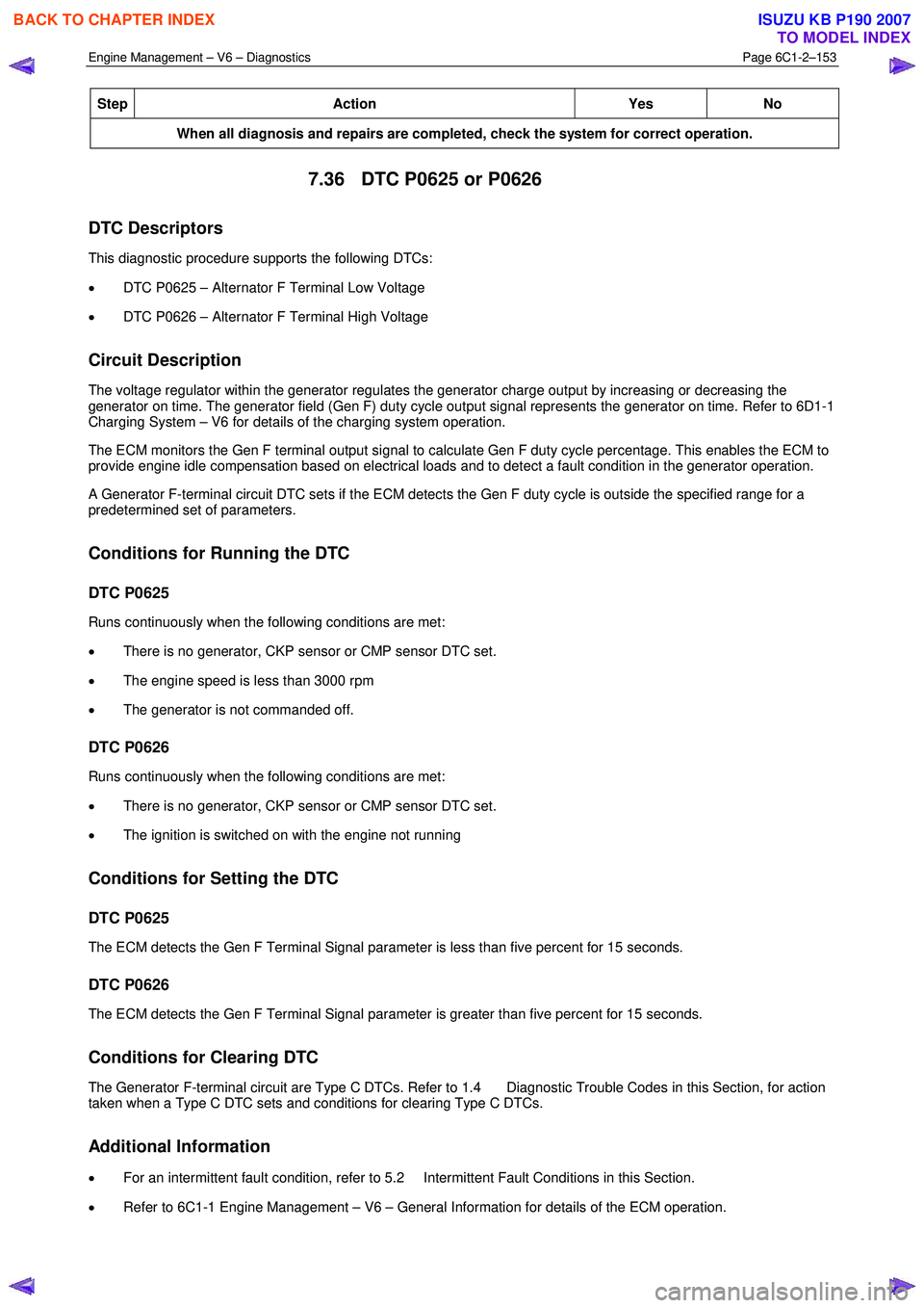
Step Action Yes No
When all diagnosis and repairs are completed, check the system for correct operation.
7.36 DTC P0625 or P0626
DTC Descriptors
This diagnostic procedure supports the following DTCs:
• DTC P0625 – Alternator F Terminal Low Voltage
• DTC P0626 – Alternator F Terminal High Voltage
Circuit Description
The voltage regulator within the generator regulates the generator charge output by increasing or decreasing the
generator on time. The generator field (Gen F) duty cycle output signal represents the generator on time. Refer to 6D1-1
Charging System – V6 for details of the charging system operation.
The ECM monitors the Gen F terminal output signal to calculate Gen F duty cycle percentage. This enables the ECM to
provide engine idle compensation based on electrical loads and to detect a fault condition in the generator operation.
A Generator F-terminal circuit DTC sets if the ECM detects the Gen F duty cycle is outside the specified range for a
predetermined set of parameters.
Conditions for Running the DTC
DTC P0625
Runs continuously when the following conditions are met:
• There is no generator, CKP sensor or CMP sensor DTC set.
• The engine speed is less than 3000 rpm
• The generator is not commanded off.
DTC P0626
Runs continuously when the following conditions are met:
• There is no generator, CKP sensor or CMP sensor DTC set.
• The ignition is switched on with the engine not running
Conditions for Setting the DTC
DTC P0625
The ECM detects the Gen F Terminal Signal parameter is less than five percent for 15 seconds.
DTC P0626
The ECM detects the Gen F Terminal Signal parameter is greater than five percent for 15 seconds.
Conditions for Clearing DTC
The Generator F-terminal circuit are Type C DTCs. Refer to 1.4 Diagnostic Trouble Codes in this Section, for action
taken when a Type C DTC sets and conditions for clearing Type C DTCs.
Additional Information
• For an intermittent fault condition, refer to 5.2 Intermittent Fault Conditions in this Section.
• Refer to 6C1-1 Engine Management – V6 – General Information for details of the ECM operation.
BACK TO CHAPTER INDEX
TO MODEL INDEX
ISUZU KB P190 2007
Page 3432 of 6020
Engine Management – V6 – Diagnostics Page 6C1-2–154
• Refer to 6D1-1 Charging System – V6 for details of the charging system operation.
• Since fault condition in a wiring connector may trigger DTCs, always test the connectors related to this diagnostic
procedure for shorted terminals or poor wiring connection before replacing any component. Refer to 8A Electrical -
Body and Chassis for information on electrical fault diagnosis.
• To assist diagnosis, refer to 3 W iring Diagrams and Connector Charts in this Section, for the system wiring
diagram and connector charts.
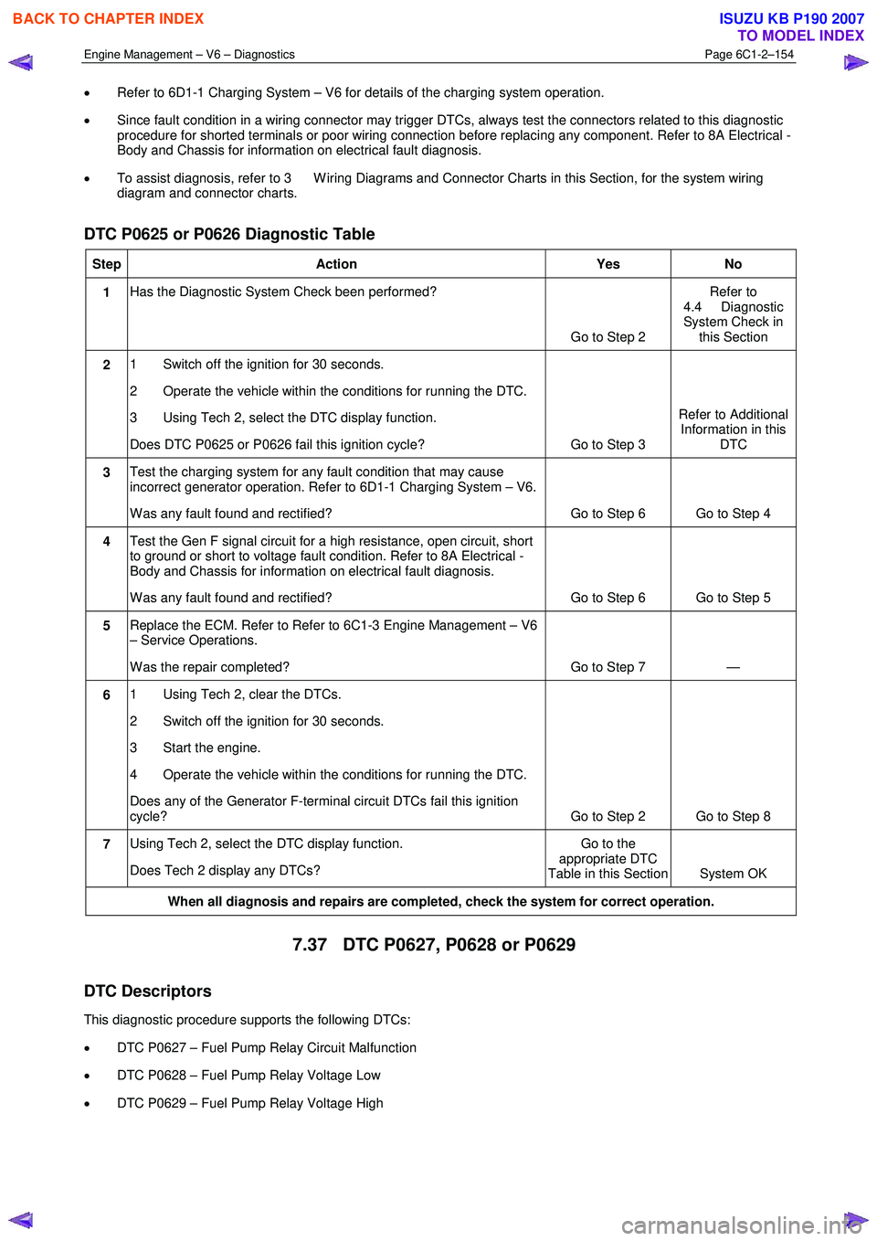
DTC P0625 or P0626 Diagnostic Table
Step Action Yes No
1 Has the Diagnostic System Check been performed?
Go to Step 2 Refer to
4.4 Diagnostic
System Check in this Section
2 1 Switch off the ignition for 30 seconds.
2 Operate the vehicle within the conditions for running the DTC.
3 Using Tech 2, select the DTC display function.
Does DTC P0625 or P0626 fail this ignition cycle? Go to Step 3 Refer to Additional
Information in this DTC
3 Test the charging system for any fault condition that may cause
incorrect generator operation. Refer to 6D1-1 Charging System – V6.
W as any fault found and rectified? Go to Step 6 Go to Step 4
4 Test the Gen F signal circuit for a high resistance, open circuit, short
to ground or short to voltage fault condition. Refer to 8A Electrical -
Body and Chassis for information on electrical fault diagnosis.
W as any fault found and rectified? Go to Step 6 Go to Step 5
5 Replace the ECM. Refer to Refer to 6C1-3 Engine Management – V6
– Service Operations.
W as the repair completed? Go to Step 7 —
6 1 Using Tech 2, clear the DTCs.
2 Switch off the ignition for 30 seconds.
3 Start the engine.
4 Operate the vehicle within the conditions for running the DTC.
Does any of the Generator F-terminal circuit DTCs fail this ignition
cycle? Go to Step 2 Go to Step 8
7 Using Tech 2, select the DTC display function.
Does Tech 2 display any DTCs? Go to the
appropriate DTC
Table in this Section System OK
When all diagnosis and repairs are completed, check the system for correct operation.
7.37 DTC P0627, P0628 or P0629
DTC Descriptors
This diagnostic procedure supports the following DTCs:
• DTC P0627 – Fuel Pump Relay Circuit Malfunction
• DTC P0628 – Fuel Pump Relay Voltage Low
• DTC P0629 – Fuel Pump Relay Voltage High
BACK TO CHAPTER INDEX
TO MODEL INDEX
ISUZU KB P190 2007
Page 3445 of 6020
Engine Management – V6 – Diagnostics Page 6C1-2–167
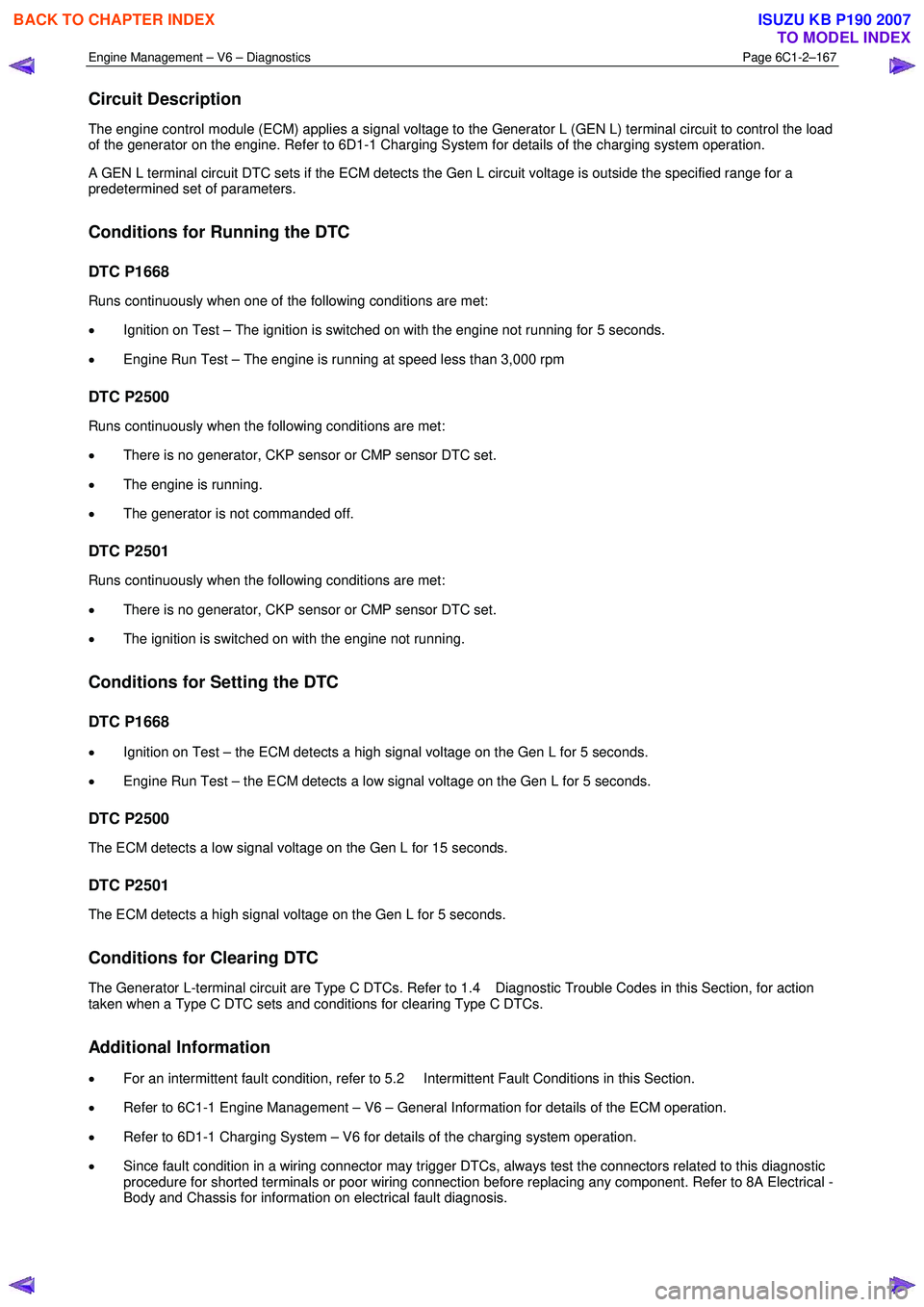
Circuit Description
The engine control module (ECM) applies a signal voltage to the Generator L (GEN L) terminal circuit to control the load
of the generator on the engine. Refer to 6D1-1 Charging System for details of the charging system operation.
A GEN L terminal circuit DTC sets if the ECM detects the Gen L circuit voltage is outside the specified range for a
predetermined set of parameters.
Conditions for Running the DTC
DTC P1668
Runs continuously when one of the following conditions are met:
• Ignition on Test – The ignition is switched on with the engine not running for 5 seconds.
• Engine Run Test – The engine is running at speed less than 3,000 rpm
DTC P2500
Runs continuously when the following conditions are met:
• There is no generator, CKP sensor or CMP sensor DTC set.
• The engine is running.
• The generator is not commanded off.
DTC P2501
Runs continuously when the following conditions are met:
• There is no generator, CKP sensor or CMP sensor DTC set.
• The ignition is switched on with the engine not running.
Conditions for Setting the DTC
DTC P1668
• Ignition on Test – the ECM detects a high signal voltage on the Gen L for 5 seconds.
• Engine Run Test – the ECM detects a low signal voltage on the Gen L for 5 seconds.
DTC P2500
The ECM detects a low signal voltage on the Gen L for 15 seconds.
DTC P2501
The ECM detects a high signal voltage on the Gen L for 5 seconds.
Conditions for Clearing DTC
The Generator L-terminal circuit are Type C DTCs. Refer to 1.4 Diagnostic Trouble Codes in this Section, for action
taken when a Type C DTC sets and conditions for clearing Type C DTCs.
Additional Information
• For an intermittent fault condition, refer to 5.2 Intermittent Fault Conditions in this Section.
• Refer to 6C1-1 Engine Management – V6 – General Information for details of the ECM operation.
• Refer to 6D1-1 Charging System – V6 for details of the charging system operation.
• Since fault condition in a wiring connector may trigger DTCs, always test the connectors related to this diagnostic
procedure for shorted terminals or poor wiring connection before replacing any component. Refer to 8A Electrical -
Body and Chassis for information on electrical fault diagnosis.
BACK TO CHAPTER INDEX
TO MODEL INDEX
ISUZU KB P190 2007