2007 ISUZU KB P190 oil
[x] Cancel search: oilPage 3244 of 6020
Engine Management – V6 – General Information Page 6C1-1–2
3.9 Serial Data Communication System ................................................................................................................... 17
3.10 Self Diagnostics System ..................................................................................................................................... 17
3.11 Service Programming System ..................................................................................................... ....................... 17
3.12 Immobiliser System ............................................................................................................................................. 18
4 Component Description and Operation ............................................................................................ .19
4.1 A/C Refrigerant Pressure Sensor ....................................................................................................................... 19
4.2 Brake Pedal Switch Assembly ............................................................................................................................ 19
Stop Lamp and Initial Brake Apply Switch ....................................................................................... ................. 19
Stop Lamp Switch ............................................................................................................................................ 19
Initial Brake Apply Switch ..................................................................................................... ............................ 19
4.3 Barometric Pressure Sensor..................................................................................................... .......................... 20
4.4 Camshaft Position Sensor .................................................................................................................................. 20
4.5 Crankshaft Position Sensor ................................................................................................................................ 21
4.6 Clutch Pedal Switch Assembly – Manual Vehicles Only ............................................................................ ...... 22
4.7 Engine Control Module........................................................................................................................................ 22
4.8 Engine Coolant Temperature Sensor .............................................................................................. ................... 23
4.9 Electric Cooling Fans .......................................................................................................................................... 23
4.10 Engine Oil Level and Temperature Sensor ........................................................................................ ................ 24
Engine Oil Temperature Sensor ......................................................................................................................... 24
Engine Oil Level Sensor ...................................................................................................................................... 25
4.11 Engine Oil Pressure Sensor..................................................................................................... ........................... 25
4.12 Fuel Injectors........................................................................................................................................................ 26
4.13 Fuel Rail Assembly ............................................................................................................. ................................. 27
4.14 Heated Oxygen Sensors .......................................................................................................... ............................ 27
LSF 4.2 Two-step Planar Heated Oxygen Sensors .................................................................................. ......... 27
LSU 4.2 Wide-band Planar Heated Oxygen Sensors ................................................................................. ....... 29
4.15 Ignition Coil and Spark Plug ............................................................................................................................... 31
4.16 Intake Air Temperature Sensor .................................................................................................. ......................... 32
4.17 Knock Sensor ....................................................................................................................................................... 32
4.18 Mass Air Flow Sensor........................................................................................................... ............................... 33
Air Intake System ................................................................................................................................................. 33
Mass Air Flow Sensor........................................................................................................... ............................... 33
Construction ..................................................................................................................................................... 34
Operation ......................................................................................................................................................... 34
5 Abbreviations and Glossary of Terms ............................................................................................ ...35
BACK TO CHAPTER INDEX
TO MODEL INDEX
ISUZU KB P190 2007
Page 3245 of 6020
Engine Management – V6 – General Information Page 6C1-1–3
1 General Information
The V6 engine management system
incorporates functions and components that
could cause personal injury or vehicle
damage. Refer to 6C1-2 Engine Management –
V6 – Diagnostics, and 6C1-3 Engine
Management – V6 – Service Operations,
before attempting any diagnosis or repairs.
1.1 Introduction
The V6 engine management system is designed to improve engine performance and increase vehicle safety while
meeting the stringent Euro 3 vehicle emission standard. This is achieved by the introduction of the following engine
management sub-systems and components:
• Throttle actuator control (TAC) System – the TAC system allows the engine control module (ECM) to electronically
control the throttle plate opening eliminating the need for the following components:
• mechanical link between the throttle plate and accelerator pedal,
• cruise control module, and
• idle air control motor.
Refer to 3.5 Throttle Actuator Control System for details of the TAC System operation and to 3.6 Cruise Control System for details of the cruise control operation.
This feature results in improved driveability, better fuel economy and emission control.
• W ide band heated oxygen sensor provides a more accurate measurement of the oxygen concentration in the
exhaust gas. Refer to 4.14 Heated Oxygen Sensors.
• Dual spray fuel injectors are now used. The use of this spray pattern is used in engines with two intake valves per
cylinder. The dual spray is achieved by having two openings in the spray orifice disc that are arranged in such a
way that two fuel sprays result, being aimed at each intake valve port. Refer to 4.12 Fuel Injectors.
• Pencil Coil – allows the ignition coil to be fitted directly on the spark plug eliminating the need for spark plug wires.
Refer to 4.15 Ignition Coil and Spark Plug.
The engine management system has a self diagnostic capability, as well as connections to enable diagnosis of faults. If
the ECM recognises operational problems it can alert the driver via the malfunction indicator lamp (MIL) in the instrument
cluster. The ECM also interfaces with other systems in the vehicle as required.
For further information on the air-conditioning system refer to 2A Heater and Air-conditioning,
For the location of fuses, fusible links and relays, refer to 8A Electrical-Body and Chassis.
1.2 Emission Control
ADR 79/01 Emissions Standards
MY2006 I190 Rodeo has been configured to comply with Australian Design Rule 79/01, that adopts the technical
requirements of the European Council Directive 98/69/EC. Commonly referred to as “Euro 3”, the new legislation
modifies the exhaust emissions, compared to the existing ADR 37/01 (or ‘Euro 2’) vehicle emissions standards.
Australian Design Rule 79/01 implements the 'Euro 3' exhaust and evaporative emissions requirements for petrol fuelled
passenger cars, forward control vehicles and passenger off-road vehicles with a gross vehicle mass (GVM) up to 3.5
tonnes. All new vehicles within these categories and first registered from January 1, 2006 must comply with ADR 79/01.
The next table shows a comparison between the existing ADR 37/01 (‘Euro 2’) and ADR 79/01 (‘Euro 3’) Hydrocarbons
Carbon
Monoxide (g/km) Exhaust
(g/km) Evaporative
(g/test) Oxides of Nitrogen
(g/km) Particulate
Matter (g/test)
BACK TO CHAPTER INDEX
TO MODEL INDEX
ISUZU KB P190 2007
Page 3248 of 6020
Engine Management – V6 – General Information Page 6C1-1–6
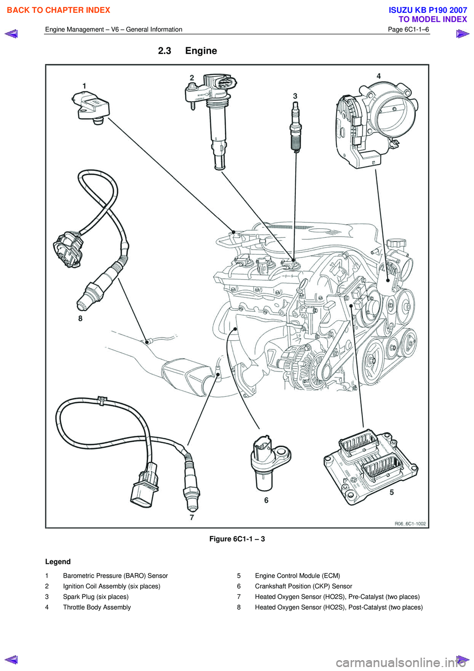
2.3 Engine
Figure 6C1-1 – 3
Legend
1 Barometric Pressure (BARO) Sensor
2 Ignition Coil Assembly (six places)
3 Spark Plug (six places)
4 Throttle Body Assembly 5 Engine Control Module (ECM)
6 Crankshaft Position (CKP) Sensor
7 Heated Oxygen Sensor (HO2S), Pre-Catalyst (two places)
8 Heated Oxygen Sensor (HO2S), Post-Catalyst (two places)
BACK TO CHAPTER INDEX
TO MODEL INDEX
ISUZU KB P190 2007
Page 3249 of 6020
Engine Management – V6 – General Information Page 6C1-1–7
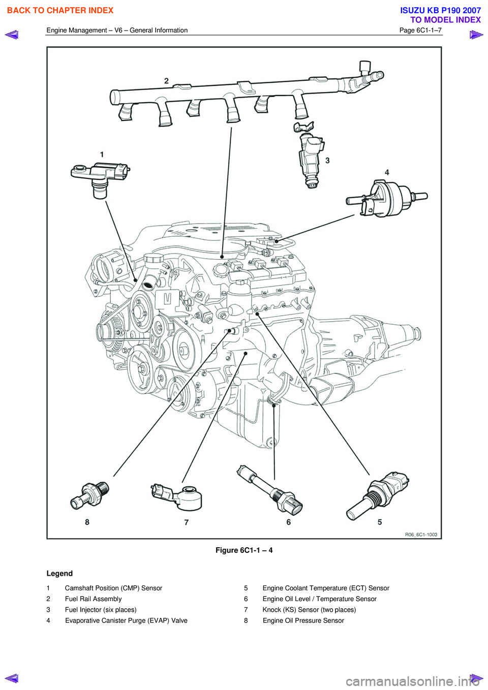
Figure 6C1-1 – 4
Legend
1 Camshaft Position (CMP) Sensor
2 Fuel Rail Assembly
3 Fuel Injector (six places)
4 Evaporative Canister Purge (EVAP) Valve 5 Engine Coolant Temperature (ECT) Sensor
6 Engine Oil Level / Temperature Sensor
7 Knock (KS) Sensor (two places)
8 Engine Oil Pressure Sensor
BACK TO CHAPTER INDEX
TO MODEL INDEX
ISUZU KB P190 2007
Page 3251 of 6020
Engine Management – V6 – General Information Page 6C1-1–9
3 System Operation
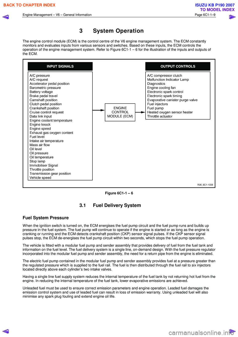
The engine control module (ECM) is the control centre of the V6 engine management system. The ECM constantly
monitors and evaluates inputs from various sensors and switches. Based on these inputs, the ECM controls the
operation of the engine management system. Refer to Figure 6C1-1 – 6 for the illustration of the inputs and outputs of
the ECM.
Figure 6C1-1 – 6
3.1 Fuel Delivery System
Fuel System Pressure
W hen the ignition switch is turned on, the ECM energises the fuel pump circuit and the fuel pump runs and builds up
pressure in the fuel system. The fuel pump will continue to operate if the engine is started or as long as the engine is
cranking or running and the ECM detects crankshaft position (CKP) sensor signal pulses. If the CKP sensor signal
pulses stop, the ECM de-energises the fuel pump circuit within two seconds, which stops the fuel pump operation.
The vehicle is fitted with a modular fuel pump and sender assembly that provides delivery of fuel from the fuel tank and
information on the fuel level. The fuel delivery system is a single line, on-demand design. W ith the fuel pressure regulator
incorporated into the modular fuel pump and sender assembly, the need for a return pipe from the engine is eliminated.
The electric fuel pump contained in the modular fuel pump and sender assembly provides fuel at a pressure greater than
the regulated pressure which is supplied to the fuel rail. The fuel is then distributed through the fuel rail to six injectors
located directly above each cylinder’s two intake valves.
Having a single line fuel supply system reduces the internal temperature of the fuel tank by not returning hot fuel from the
engine. In reducing the internal temperature of the fuel tank, lower evaporative emissions are achieved.
Unleaded fuel must be used to ensure correct emission parameters and engine operation. Leaded fuel damages the
emission control system and use of leaded fuel can result in loss of emission warranty. Using unleaded fuel will also
minimise any spark plug fouling and extend engine oil life.
BACK TO CHAPTER INDEX
TO MODEL INDEX
ISUZU KB P190 2007
Page 3254 of 6020
Engine Management – V6 – General Information Page 6C1-1–12
Battery Voltage Correction Mode
The ECM monitors the battery voltage circuit to ensure the voltage available to the engine management system stays
within the specified range. A low system voltage changes the voltage across the fuel injectors, which affects the fuel
injector flow rate. In addition, a low system voltage fault condition may cause other engine management system
components to malfunction.
The ECM switches to battery voltage correction mode when the ECM detects a low battery voltage fault condition. W hile
in battery voltage correction mode, the ECM performs the following functions to compensate for the low system voltage:
• Increases the injector on-time to maintain the correct amount of fuel being delivered, and
• Increases the idle speed to increase the generator output.
Limp Mode
The programming in the ECM software allows the engine to run in a back-up fuel strategy or limp mode when the ECM
fails to receive signal inputs from critical sensors or when a critical engine management fault condition exists.
The ECM switches to limp mode to enable the vehicle to be driven until service operations can be performed.
Engine Protection Mode
Engine protection mode is engaged to protect engine components from friction damage in the event of an engine over-
temperature condition being detected by the ECM.
W hen the ECM is in engine protection mode, fuel injectors are systematically disabled and re-activated. The injectors
that have been shut down allow the air being drawn into the engine to assist with engine cooling.
Clear Flood Mode
If the engine is flooded with fuel during starting and will not start, the clear flood mode can be manually selected by
depressing the accelerator pedal to wide open throttle (W OT). In this mode, the ECM will completely disable the fuel
injectors, and will maintain this state during engine cranking as long as the ECM detects a W OT condition with engine
speed less than 1,000 rpm.
3.3 Ignition Control System
The electronic ignition system provides a spark to ignite the compressed air / fuel mixture at the correct time. The ECM
maintains correct spark timing and dwell for all engine operating conditions. The ECM calculates the optimum spark
parameters from information received from the various sensors and triggers the appropriate ignition module / coil to fire
the spark plug.
3.4 Starter Motor Operation
The engine control module controls the activation of the start relay in response to inputs from:
• Ignition switch,
• Battery,
• Immobiliser system, and
• Automatic transmission gear selector position / clutch pedal position switch for vehicles with manual transmissions.
3.5 Throttle Actuator Control System
Description
The throttle actuator control (TAC) system is used to improve emissions, fuel economy and driveability. The TAC system
eliminates the mechanical link between the accelerator pedal and the throttle plate and eliminates the need for a cruise
control module and idle air control motor. The TAC system comprises of:
BACK TO CHAPTER INDEX
TO MODEL INDEX
ISUZU KB P190 2007
Page 3263 of 6020
Engine Management – V6 – General Information Page 6C1-1–21
4.5 Crankshaft Position Sensor
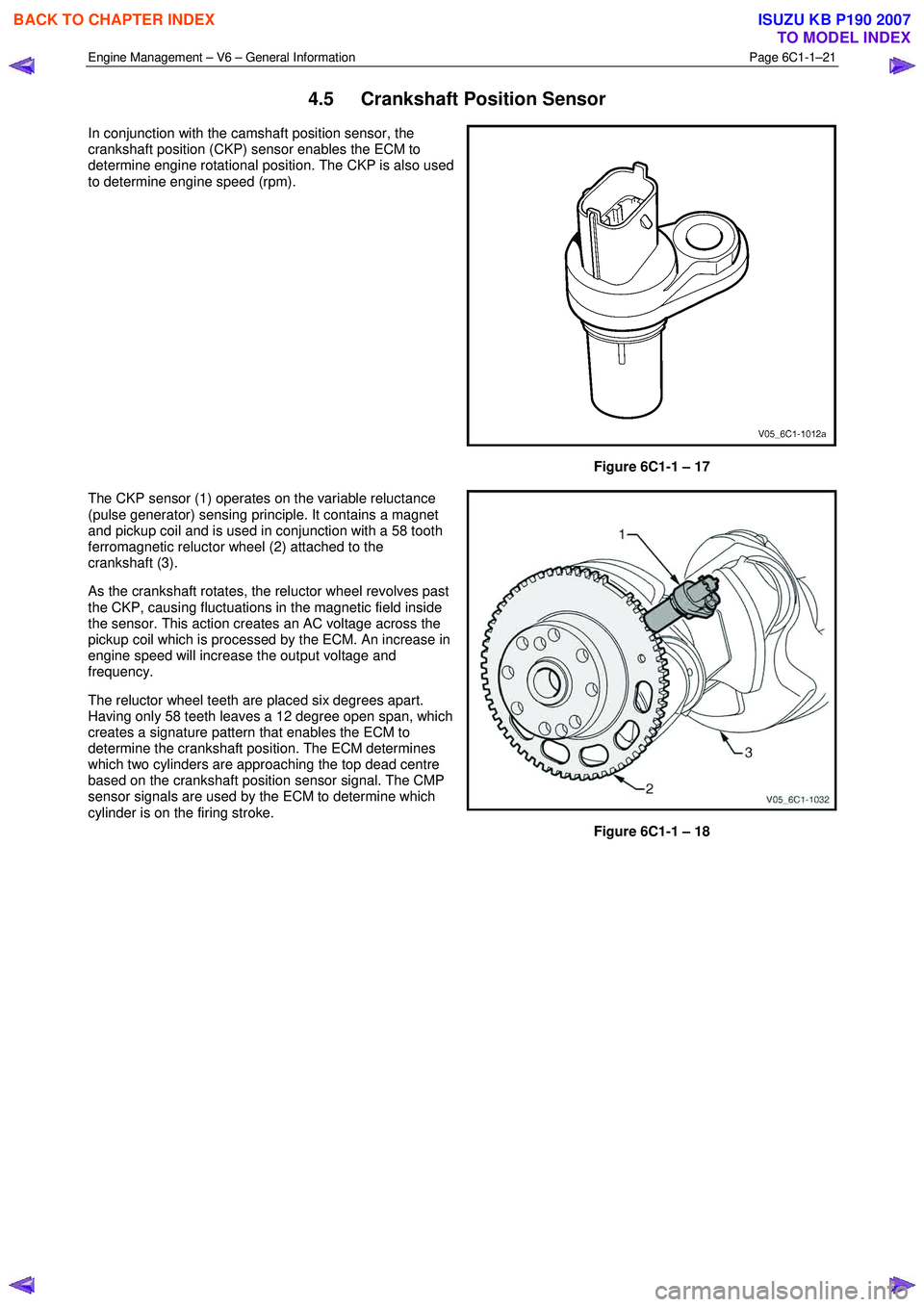
In conjunction with the camshaft position sensor, the
crankshaft position (CKP) sensor enables the ECM to
determine engine rotational position. The CKP is also used
to determine engine speed (rpm).
Figure 6C1-1 – 17
The CKP sensor (1) operates on the variable reluctance
(pulse generator) sensing principle. It contains a magnet
and pickup coil and is used in conjunction with a 58 tooth
ferromagnetic reluctor wheel (2) attached to the
crankshaft (3).
As the crankshaft rotates, the reluctor wheel revolves past
the CKP, causing fluctuations in the magnetic field inside
the sensor. This action creates an AC voltage across the
pickup coil which is processed by the ECM. An increase in
engine speed will increase the output voltage and
frequency.
The reluctor wheel teeth are placed six degrees apart.
Having only 58 teeth leaves a 12 degree open span, which
creates a signature pattern that enables the ECM to
determine the crankshaft position. The ECM determines
which two cylinders are approaching the top dead centre
based on the crankshaft position sensor signal. The CMP
sensor signals are used by the ECM to determine which
cylinder is on the firing stroke.
Figure 6C1-1 – 18
BACK TO CHAPTER INDEX
TO MODEL INDEX
ISUZU KB P190 2007
Page 3264 of 6020
Engine Management – V6 – General Information Page 6C1-1–22
4.6 Clutch Pedal Switch Assembly – Manual
Vehicles Only
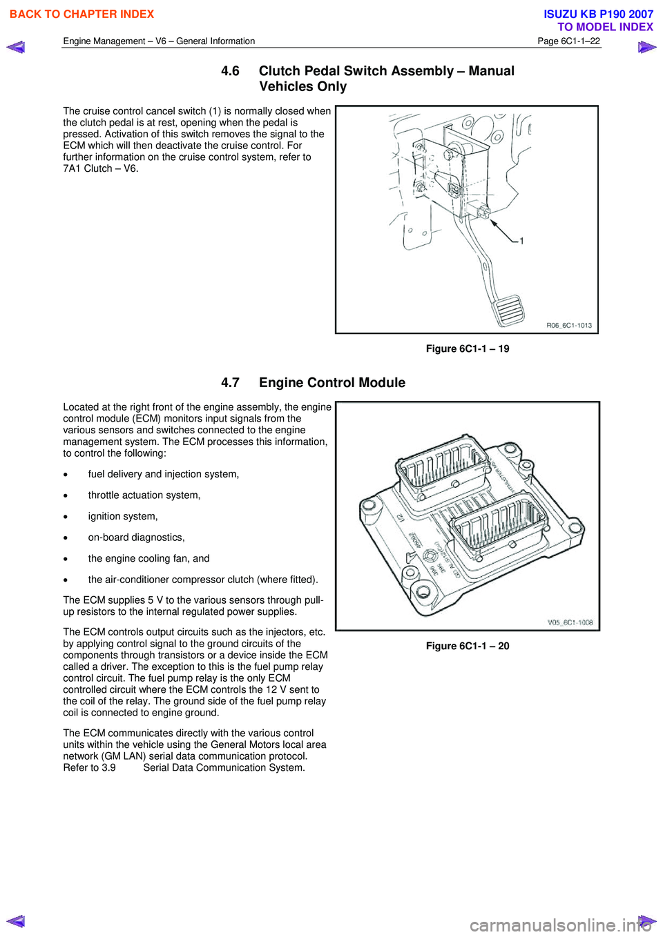
The cruise control cancel switch (1) is normally closed when
the clutch pedal is at rest, opening when the pedal is
pressed. Activation of this switch removes the signal to the
ECM which will then deactivate the cruise control. For
further information on the cruise control system, refer to
7A1 Clutch – V6.
Figure 6C1-1 – 19
4.7 Engine Control Module
Located at the right front of the engine assembly, the engine
control module (ECM) monitors input signals from the
various sensors and switches connected to the engine
management system. The ECM processes this information,
to control the following:
• fuel delivery and injection system,
• throttle actuation system,
• ignition system,
• on-board diagnostics,
• the engine cooling fan, and
• the air-conditioner compressor clutch (where fitted).
The ECM supplies 5 V to the various sensors through pull-
up resistors to the internal regulated power supplies.
The ECM controls output circuits such as the injectors, etc.
by applying control signal to the ground circuits of the
components through transistors or a device inside the ECM
called a driver. The exception to this is the fuel pump relay
control circuit. The fuel pump relay is the only ECM
controlled circuit where the ECM controls the 12 V sent to
the coil of the relay. The ground side of the fuel pump relay
coil is connected to engine ground.
The ECM communicates directly with the various control
units within the vehicle using the General Motors local area
network (GM LAN) serial data communication protocol.
Refer to 3.9 Serial Data Communication System.
Figure 6C1-1 – 20
BACK TO CHAPTER INDEX
TO MODEL INDEX
ISUZU KB P190 2007