2007 ISUZU KB P190 oil
[x] Cancel search: oilPage 3266 of 6020
Engine Management – V6 – General Information Page 6C1-1–24
4.10 Engine Oil Level and Temperature
Sensor
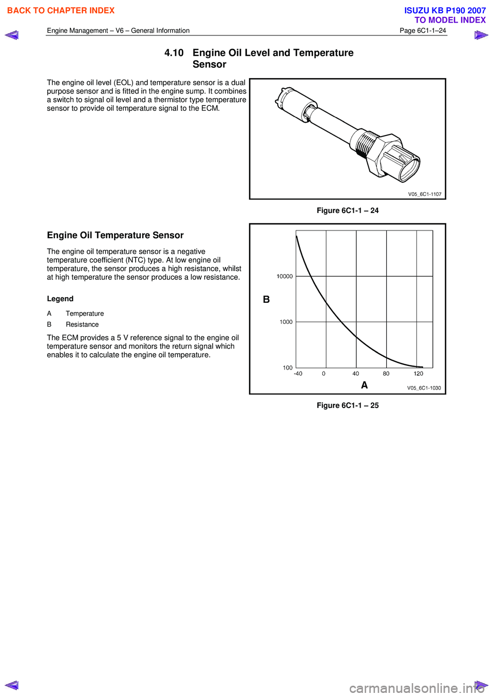
The engine oil level (EOL) and temperature sensor is a dual
purpose sensor and is fitted in the engine sump. It combines
a switch to signal oil level and a thermistor type temperature
sensor to provide oil temperature signal to the ECM.
Figure 6C1-1 – 24
Engine Oil Temperature Sensor
The engine oil temperature sensor is a negative
temperature coefficient (NTC) type. At low engine oil
temperature, the sensor produces a high resistance, whilst
at high temperature the sensor produces a low resistance.
Legend
A Temperature
B Resistance
The ECM provides a 5 V reference signal to the engine oil
temperature sensor and monitors the return signal which
enables it to calculate the engine oil temperature.
Figure 6C1-1 – 25
BACK TO CHAPTER INDEX
TO MODEL INDEX
ISUZU KB P190 2007
Page 3267 of 6020
Engine Management – V6 – General Information Page 6C1-1–25
Engine Oil Level Sensor
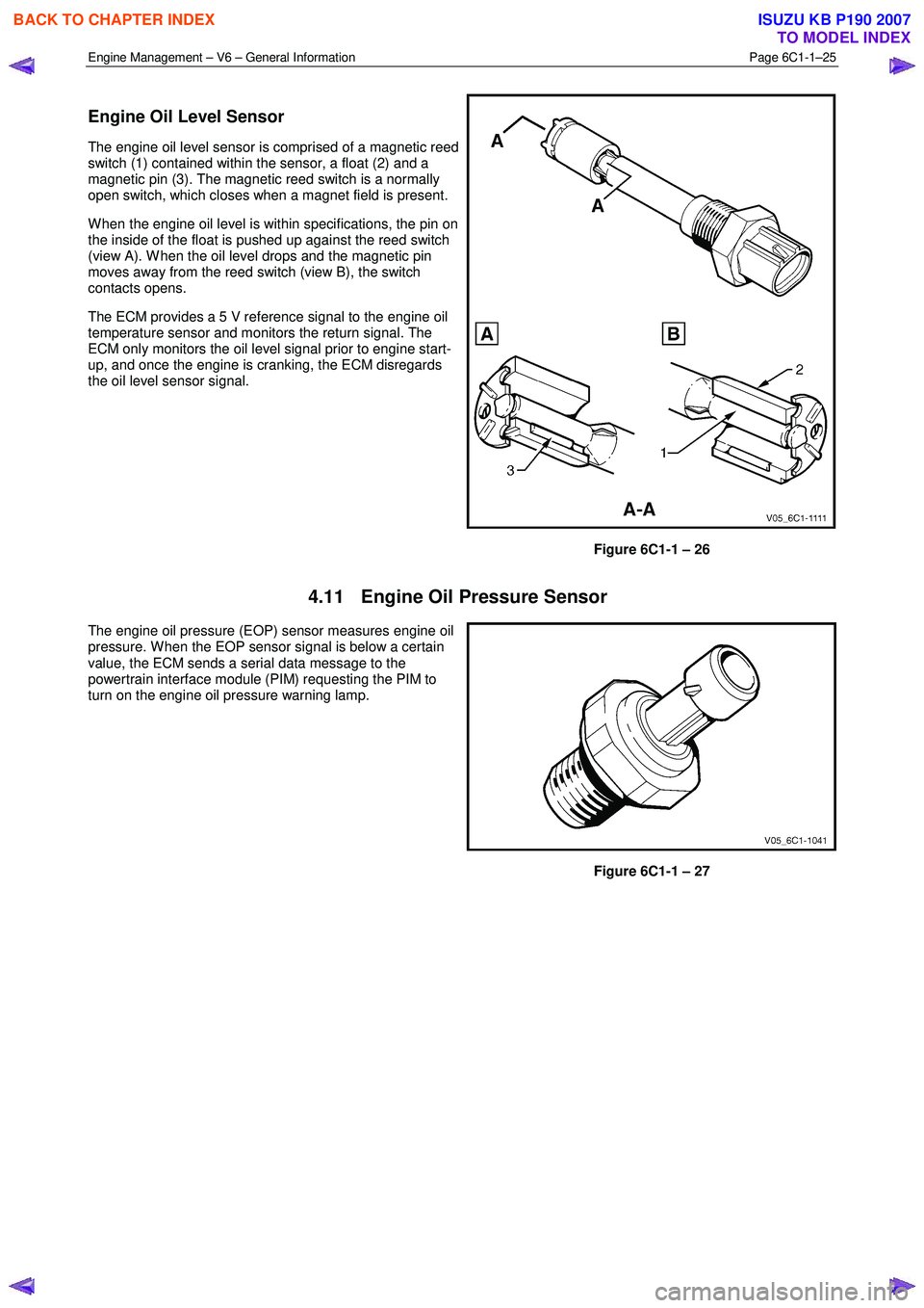
The engine oil level sensor is comprised of a magnetic reed
switch (1) contained within the sensor, a float (2) and a
magnetic pin (3). The magnetic reed switch is a normally
open switch, which closes when a magnet field is present.
W hen the engine oil level is within specifications, the pin on
the inside of the float is pushed up against the reed switch
(view A). W hen the oil level drops and the magnetic pin
moves away from the reed switch (view B), the switch
contacts opens.
The ECM provides a 5 V reference signal to the engine oil
temperature sensor and monitors the return signal. The
ECM only monitors the oil level signal prior to engine start-
up, and once the engine is cranking, the ECM disregards
the oil level sensor signal.
Figure 6C1-1 – 26
4.11 Engine Oil Pressure Sensor
The engine oil pressure (EOP) sensor measures engine oil
pressure. W hen the EOP sensor signal is below a certain
value, the ECM sends a serial data message to the
powertrain interface module (PIM) requesting the PIM to
turn on the engine oil pressure warning lamp.
Figure 6C1-1 – 27
BACK TO CHAPTER INDEX
TO MODEL INDEX
ISUZU KB P190 2007
Page 3268 of 6020
Engine Management – V6 – General Information Page 6C1-1–26
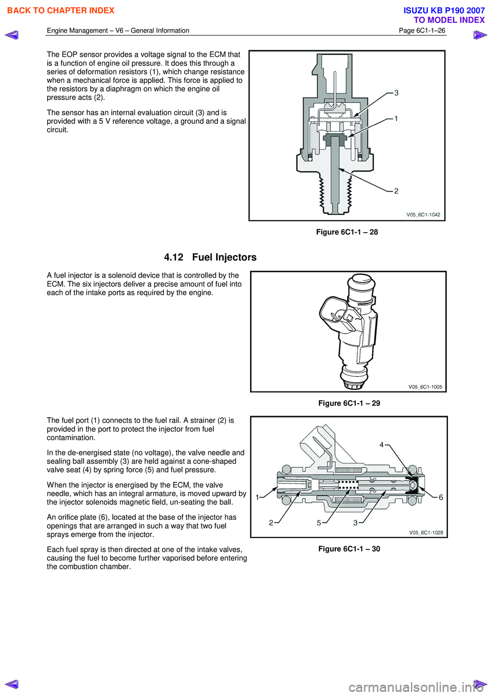
The EOP sensor provides a voltage signal to the ECM that
is a function of engine oil pressure. It does this through a
series of deformation resistors (1), which change resistance
when a mechanical force is applied. This force is applied to
the resistors by a diaphragm on which the engine oil
pressure acts (2).
The sensor has an internal evaluation circuit (3) and is
provided with a 5 V reference voltage, a ground and a signal
circuit.
Figure 6C1-1 – 28
4.12 Fuel Injectors
A fuel injector is a solenoid device that is controlled by the
ECM. The six injectors deliver a precise amount of fuel into
each of the intake ports as required by the engine.
Figure 6C1-1 – 29
The fuel port (1) connects to the fuel rail. A strainer (2) is
provided in the port to protect the injector from fuel
contamination.
In the de-energised state (no voltage), the valve needle and
sealing ball assembly (3) are held against a cone-shaped
valve seat (4) by spring force (5) and fuel pressure.
W hen the injector is energised by the ECM, the valve
needle, which has an integral armature, is moved upward by
the injector solenoids magnetic field, un-seating the ball.
An orifice plate (6), located at the base of the injector has
openings that are arranged in such a way that two fuel
sprays emerge from the injector.
Each fuel spray is then directed at one of the intake valves,
causing the fuel to become further vaporised before entering
the combustion chamber.
Figure 6C1-1 – 30
BACK TO CHAPTER INDEX
TO MODEL INDEX
ISUZU KB P190 2007
Page 3273 of 6020
Engine Management – V6 – General Information Page 6C1-1–31
4.15 Ignition Coil and Spark Plug
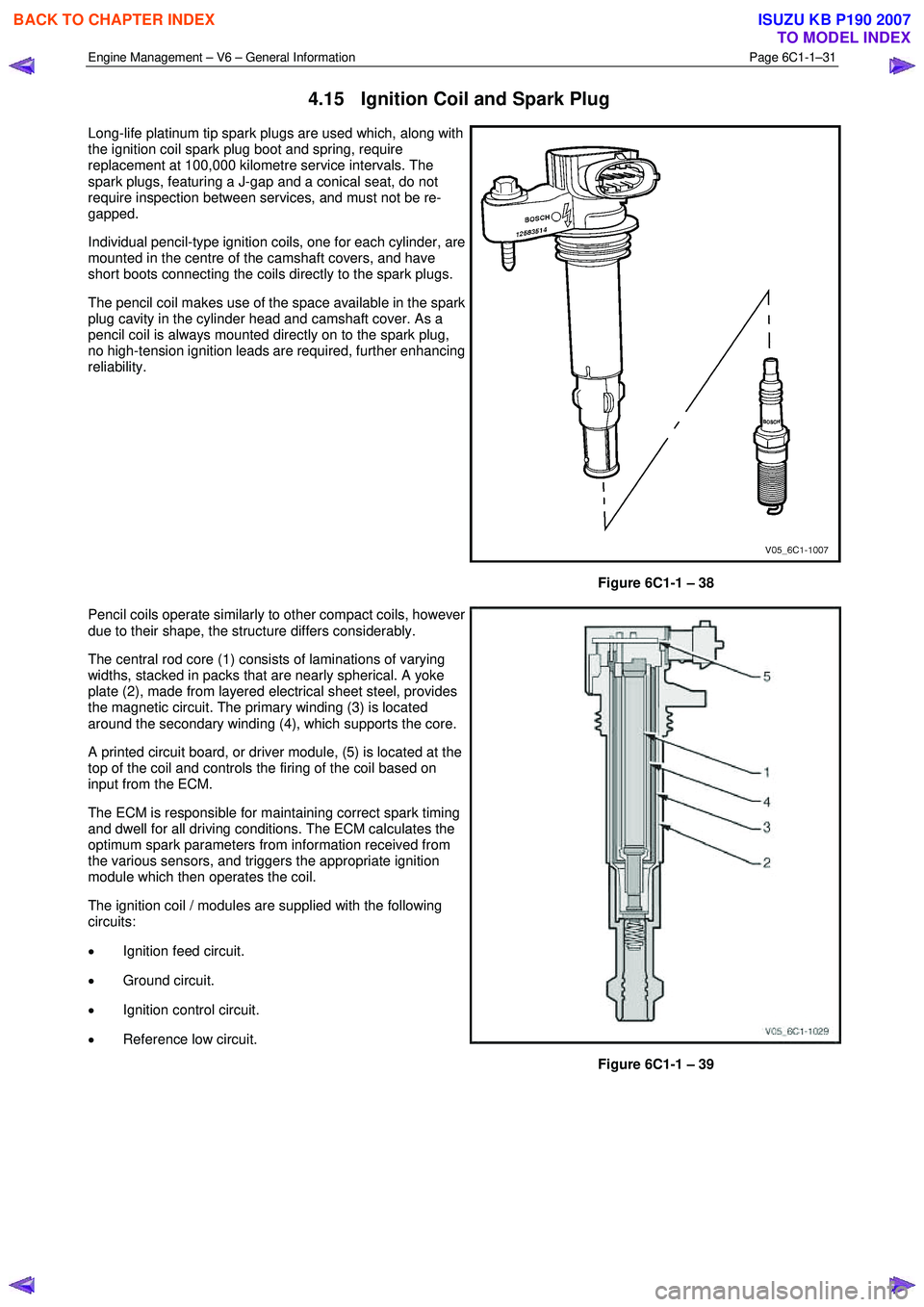
Long-life platinum tip spark plugs are used which, along with
the ignition coil spark plug boot and spring, require
replacement at 100,000 kilometre service intervals. The
spark plugs, featuring a J-gap and a conical seat, do not
require inspection between services, and must not be re-
gapped.
Individual pencil-type ignition coils, one for each cylinder, are
mounted in the centre of the camshaft covers, and have
short boots connecting the coils directly to the spark plugs.
The pencil coil makes use of the space available in the spark
plug cavity in the cylinder head and camshaft cover. As a
pencil coil is always mounted directly on to the spark plug,
no high-tension ignition leads are required, further enhancing
reliability.
Figure 6C1-1 – 38
Pencil coils operate similarly to other compact coils, however
due to their shape, the structure differs considerably.
The central rod core (1) consists of laminations of varying
widths, stacked in packs that are nearly spherical. A yoke
plate (2), made from layered electrical sheet steel, provides
the magnetic circuit. The primary winding (3) is located
around the secondary winding (4), which supports the core.
A printed circuit board, or driver module, (5) is located at the
top of the coil and controls the firing of the coil based on
input from the ECM.
The ECM is responsible for maintaining correct spark timing
and dwell for all driving conditions. The ECM calculates the
optimum spark parameters from information received from
the various sensors, and triggers the appropriate ignition
module which then operates the coil.
The ignition coil / modules are supplied with the following
circuits:
• Ignition feed circuit.
• Ground circuit.
• Ignition control circuit.
• Reference low circuit.
Figure 6C1-1 – 39
BACK TO CHAPTER INDEX
TO MODEL INDEX
ISUZU KB P190 2007
Page 3278 of 6020
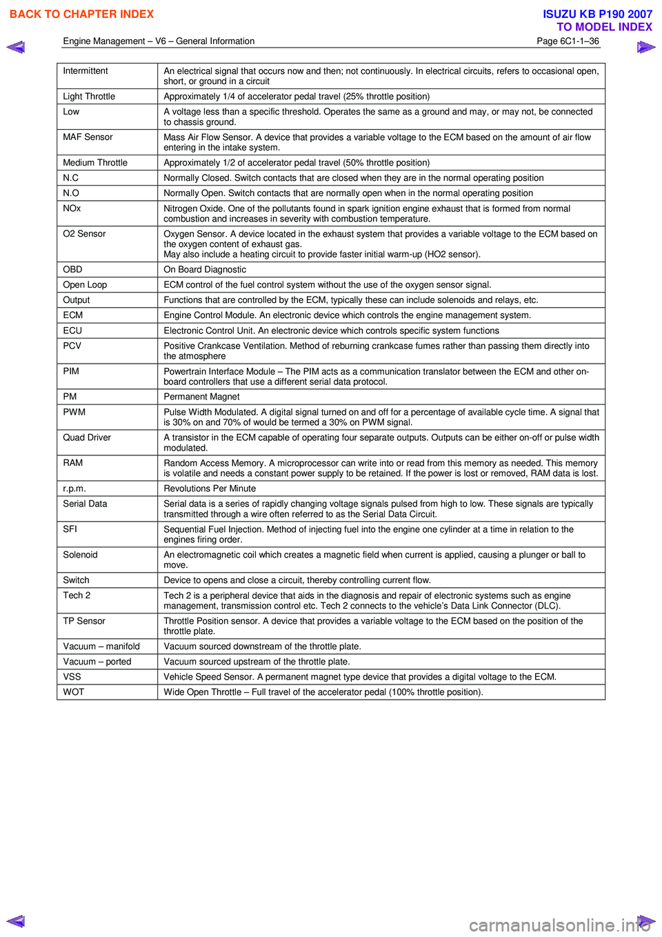
Engine Management – V6 – General Information Page 6C1-1–36
Intermittent
An electrical signal that occurs now and then; not continuously. In electrical circuits, refers to occasional open,
short, or ground in a circuit
Light Throttle Approximately 1/4 of accelerator pedal travel (25% throttle position)
Low
A voltage less than a specific threshold. Operates the same as a ground and may, or may not, be connected
to chassis ground.
MAF Sensor Mass Air Flow Sensor. A device that provides a variable voltage to the ECM based on the amount of air flow
entering in the intake system.
Medium Throttle Approximately 1/2 of accelerator pedal travel (50% throttle position)
N.C Normally Closed. Switch contacts that are closed when they are in the normal operating position
N.O Normally Open. Switch contacts that are normally open when in the normal operating position
NOx
Nitrogen Oxide. One of the pollutants found in spark ignition engine exhaust that is formed from normal
combustion and increases in severity with combustion temperature.
O2 Sensor Oxygen Sensor. A device located in the exhaust system that provides a variable voltage to the ECM based on
the oxygen content of exhaust gas.
May also include a heating circuit to provide faster initial warm-up (HO2 sensor).
OBD On Board Diagnostic
Open Loop ECM control of the fuel control system without the use of the oxygen sensor signal.
Output Functions that are controlled by the ECM, typically these can include solenoids and relays, etc.
ECM Engine Control Module. An electronic device which controls the engine management system.
ECU Electronic Control Unit. An electronic device which controls specific system functions
PCV
Positive Crankcase Ventilation. Method of reburning crankcase fumes rather than passing them directly into
the atmosphere
PIM Powertrain Interface Module – The PIM acts as a communication translator between the ECM and other on-
board controllers that use a different serial data protocol.
PM Permanent Magnet
PWM
Pulse Width Modulated. A digital signal turned on and off for a percentage of available cycle time. A signal that
is 30% on and 70% of would be termed a 30% on PWM signal.
Quad Driver A transistor in the ECM capable of operating four separate outputs. Outputs can be either on-off or pulse width
modulated.
RAM Random Access Memory. A microprocessor can write into or read from this memory as needed. This memory
is volatile and needs a constant power supply to be retained. If the power is lost or removed, RAM data is lost.
r.p.m. Revolutions Per Minute
Serial Data
Serial data is a series of rapidly changing voltage signals pulsed from high to low. These signals are typically
transmitted through a wire often referred to as the Serial Data Circuit.
SFI Sequential Fuel Injection. Method of injecting fuel into the engine one cylinder at a time in relation to the
engines firing order.
Solenoid An electromagnetic coil which creates a magnetic field when current is applied, causing a plunger or ball to
move.
Switch Device to opens and close a circuit, thereby controlling current flow.
Tech 2
Tech 2 is a peripheral device that aids in the diagnosis and repair of electronic systems such as engine
management, transmission control etc. Tech 2 connects to the vehicle’s Data Link Connector (DLC).
TP Sensor Throttle Position sensor. A device that provides a variable voltage to the ECM based on the position of the
throttle plate.
Vacuum – manifold Vacuum sourced downstream of the throttle plate.
Vacuum – ported Vacuum sourced upstream of the throttle plate.
VSS Vehicle Speed Sensor. A permanent magnet type device that provides a digital voltage to the ECM.
WOT Wide Open Throttle – Full travel of the accelerator pedal (100% throttle position).
BACK TO CHAPTER INDEX
TO MODEL INDEX
ISUZU KB P190 2007
Page 3279 of 6020
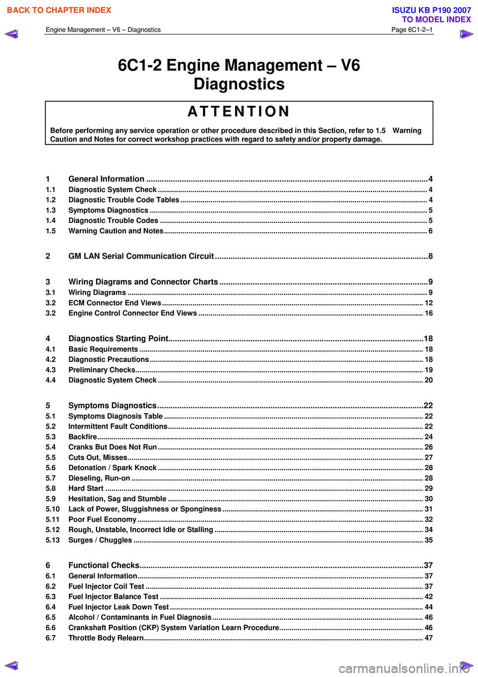
Engine Management – V6 – Diagnostics Page 6C1-2–1
6C1-2 Engine Management – V6
Diagnostics
ATTENTION
Before performing any service operation or other procedure described in this Section, refer to 1.5 Warning
Caution and Notes for correct workshop practices with regard to safety and/or property damage.
1 General Information ............................................................................................................ ...................4
1.1 Diagnostic System Check ..................................................................................................................................... 4
1.2 Diagnostic Trouble Code Tables ................................................................................................. ......................... 4
1.3 Symptoms Diagnostics ......................................................................................................................................... 5
1.4 Diagnostic Trouble Codes .................................................................................................................................... 5
1.5 Warning Caution and Notes .................................................................................................................................. 6
2 GM LAN Serial Communication Circuit ............................................................................................ ....8
3 Wiring Diagrams and Connector Charts ........................................................................................... ...9
3.1 Wiring Diagrams .................................................................................................................................................... 9
3.2 ECM Connector End Views ................................................................................................................................. 12
3.2 Engine Control Connector End Views ............................................................................................. .................. 16
4 Diagnostics Starting Point...................................................................................................................18
4.1 Basic Requirements ............................................................................................................................................ 18
4.2 Diagnostic Precautions ......................................................................................................... .............................. 18
4.3 Preliminary Checks.............................................................................................................................................. 19
4.4 Diagnostic System Check ........................................................................................................ ........................... 20
5 Symptoms Diagnostics ........................................................................................................................22
5.1 Symptoms Diagnosis Table ....................................................................................................... ......................... 22
5.2 Intermittent Fault Conditions .............................................................................................................................. 22
5.3 Backfire................................................................................................................................................................. 24
5.4 Cranks But Does Not Run ........................................................................................................ ........................... 26
5.5 Cuts Out, Misses.................................................................................................................................................. 27
5.6 Detonation / Spark Knock ....................................................................................................... ............................ 28
5.7 Dieseling, Run-on ................................................................................................................................................ 28
5.8 Hard Start ............................................................................................................................................................. 29
5.9 Hesitation, Sag and Stumble .................................................................................................... .......................... 30
5.10 Lack of Power, Sluggishness or Sponginess ...................................................................................... ............. 31
5.11 Poor Fuel Economy ............................................................................................................................................. 32
5.12 Rough, Unstable, Incorrect Idle or Stalling .................................................................................... ................... 34
5.13 Surges / Chuggles ............................................................................................................................................... 35
6 Functional Checks................................................................................................................................37
6.1 General Information ............................................................................................................ ................................. 37
6.2 Fuel Injector Coil Test ......................................................................................................................................... 37
6.3 Fuel Injector Balance Test ..................................................................................................... ............................. 42
6.4 Fuel Injector Leak Down Test ................................................................................................... .......................... 44
6.5 Alcohol / Contaminants in Fuel Diagnosis ....................................................................................... ................. 46
6.6 Crankshaft Position (CKP) System Variation Learn Procedure..................................................................... .. 46
6.7 Throttle Body Relearn.......................................................................................................................................... 47
BACK TO CHAPTER INDEX
TO MODEL INDEX
ISUZU KB P190 2007
Page 3291 of 6020
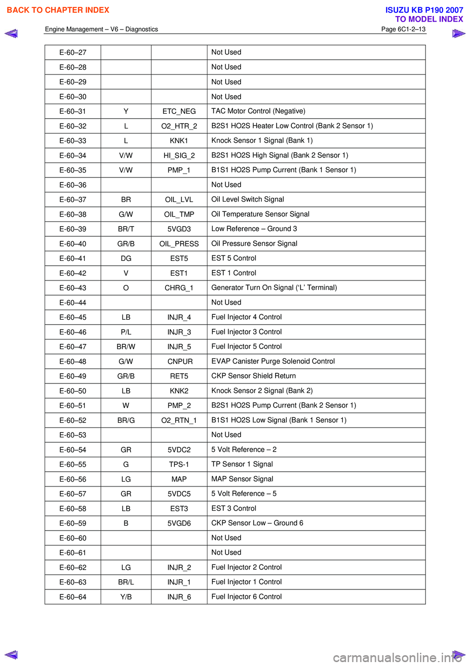
Engine Management – V6 – Diagnostics Page 6C1-2–13
E-60–27 Not Used
E-60–28 Not Used
E-60–29 Not
Used
E-60–30 Not Used
E-60–31 Y ETC_NEG TAC Motor Control (Negative)
E-60–32 L O2_HTR_2 B2S1 HO2S Heater Low Control (Bank 2 Sensor 1)
E-60–33 L KNK1 Knock Sensor 1 Signal (Bank 1)
E-60–34 V/W HI_SIG_2 B2S1 HO2S High Signal (Bank 2 Sensor 1)
E-60–35 V/W PMP_1 B1S1 HO2S Pump Current (Bank 1 Sensor 1)
E-60–36 Not Used
E-60–37 BR OIL_LVL Oil Level Switch Signal
E-60–38 G/W OIL_TMP Oil Temperature Sensor Signal
E-60–39 BR/T 5VGD3 Low Reference – Ground 3
E-60–40 GR/B OIL_PRESS Oil Pressure Sensor Signal
E-60–41 DG EST5 EST 5 Control
E-60–42 V EST1 EST 1 Control
E-60–43 O CHRG_1 Generator Turn On Signal (‘L’ Terminal)
E-60–44 Not Used
E-60–45 LB INJR_4 Fuel Injector 4 Control
E-60–46 P/L INJR_3 Fuel Injector 3 Control
E-60–47 BR/W INJR_5 Fuel Injector 5 Control
E-60–48 G/W CNPUR EVAP Canister Purge Solenoid Control
E-60–49 GR/B RET5 CKP Sensor Shield Return
E-60–50 LB KNK2 Knock Sensor 2 Signal (Bank 2)
E-60–51 W PMP_2 B2S1 HO2S Pump Current (Bank 2 Sensor 1)
E-60–52 BR/G O2_RTN_1 B1S1 HO2S Low Signal (Bank 1 Sensor 1)
E-60–53 Not Used
E-60–54 GR 5VDC2 5 Volt Reference – 2
E-60–55 G TPS-1 TP Sensor 1 Signal
E-60–56 LG MAP MAP Sensor Signal
E-60–57 GR 5VDC5 5 Volt Reference – 5
E-60–58 LB EST3 EST 3 Control
E-60–59 B 5VGD6 CKP Sensor Low – Ground 6
E-60–60 Not Used
E-60–61 Not Used
E-60–62 LG INJR_2 Fuel Injector 2 Control
E-60–63 BR/L INJR_1 Fuel Injector 1 Control
E-60–64 Y/B INJR_6 Fuel Injector 6 Control
BACK TO CHAPTER INDEX
TO MODEL INDEX
ISUZU KB P190 2007
Page 3293 of 6020
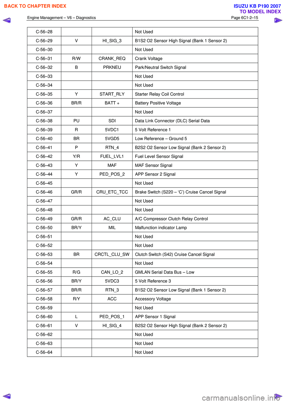
Engine Management – V6 – Diagnostics Page 6C1-2–15
C-56–28 Not Used
C-56–29 V HI_SIG_3 B1S2 O2 Sensor High Signal (Bank 1 Sensor 2)
C-56–30 Not Used
C-56–31 R/W CRANK_REQ Crank Voltage
C-56–32 B PRKNEU Park/Neutral Switch Signal
C-56–33 Not Used
C-56–34 Not Used
C-56–35 Y START_RLY Starter Relay Coil Control
C-56–36 BR/R BATT + Battery Positive Voltage
C-56–37 Not Used
C-56–38 PU SDI Data Link Connector (DLC) Serial Data
C-56–39 R 5VDC1 5 Volt Reference 1
C-56–40 BR 5VGD5 Low Reference – Ground 5
C-56–41 P RTN_4 B2S2 O2 Sensor Low Signal (Bank 2 Sensor 2)
C-56–42 Y/R FUEL_LVL1 Fuel Level Sensor Signal
C-56–43 Y MAF MAF Sensor Signal
C-56–44 Y PED_POS_2 APP Sensor 2 Signal
C-56–45 Not Used
C-56–46 GR/R CRU_ETC_TCC Brake Switch (S220 – ‘C’) Cruise Cancel Signal
C-56–47 Not Used
C-56–48 Not Used
C-56–49 GR/R AC_CLU A/C Compressor Clutch Relay Control
C-56–50 BR/Y MIL Malfunction indicator Lamp
C-56–51 Not Used
C-56–52 Not Used
C-56–53 BR CRCTL_CLU_SW Clutch Switch (S42) Cruise Cancel Signal
C-56–54 Not Used
C-56–55 R/G CAN_LO_2 GMLAN Serial Data Bus – Low
C-56–56 BR/Y 5VDC3 5 Volt Reference 3
C-56–57 BR/R RTN_3 B1S2 O2 Sensor Low Signal (Bank 1 Sensor 2)
C-56–58 R/Y ACC Accessory Voltage
C-56–59 Not Used
C-56–60 L PED_POS_1 APP Sensor 1 Signal
C-56–61 V HI_SIG_4 B2S2 O2 Sensor High Signal (Bank 2 Sensor 2)
C-56–62 Not Used
C-56–63 Not Used
C-56–64 Not Used
BACK TO CHAPTER INDEX
TO MODEL INDEX
ISUZU KB P190 2007