2007 ISUZU KB P190 oil
[x] Cancel search: oilPage 3148 of 6020
Engine Cooling – V6 Engine Page 6B1–13
2.6 Coolant Filler Cap
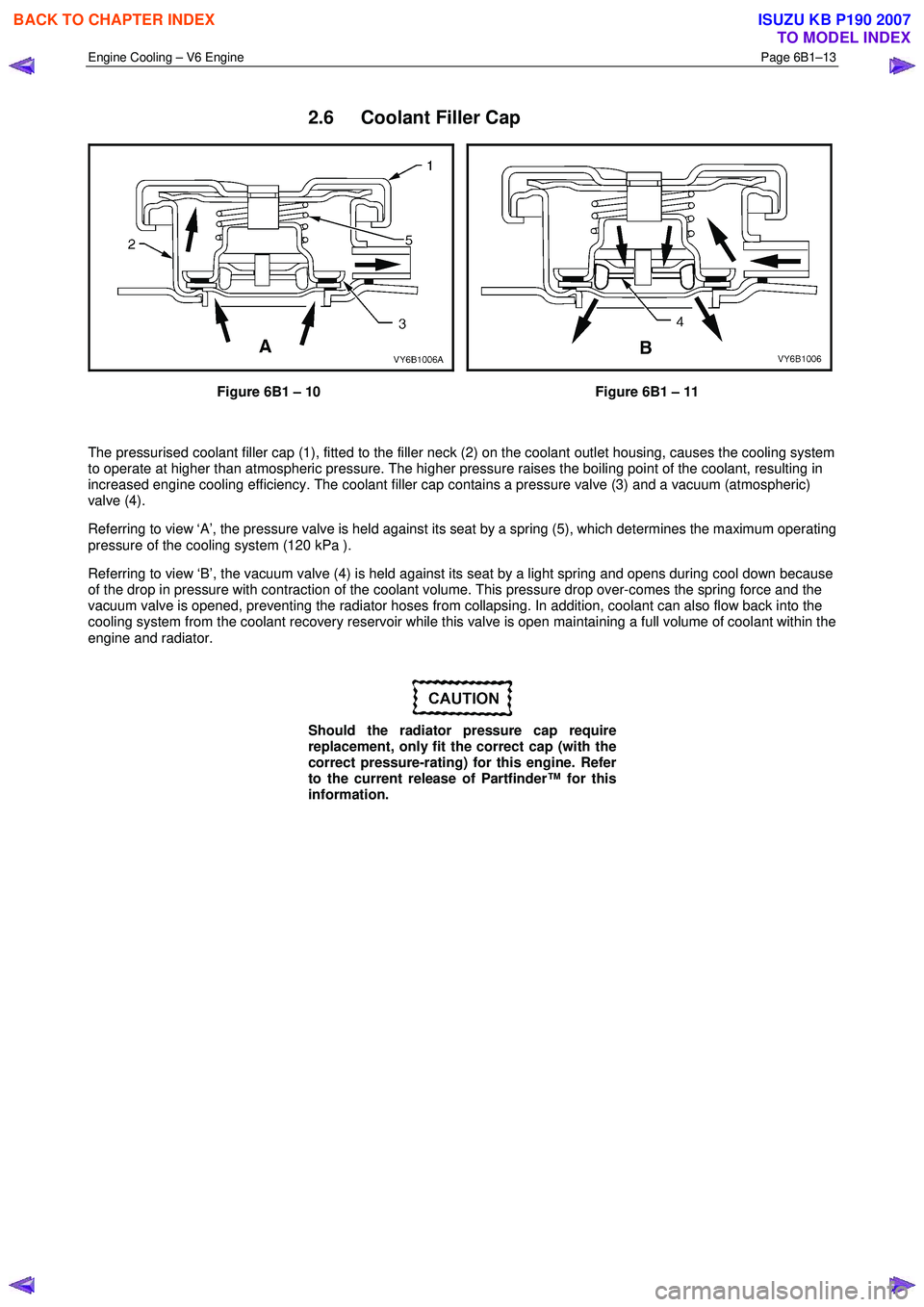
Figure 6B1 – 10 Figure 6B1 – 11
The pressurised coolant filler cap (1), fitted to the filler neck (2) on the coolant outlet housing, causes the cooling system
to operate at higher than atmospheric pressure. The higher pressure raises the boiling point of the coolant, resulting in
increased engine cooling efficiency. The coolant filler cap contains a pressure valve (3) and a vacuum (atmospheric)
valve (4).
Referring to view ‘A’, the pressure valve is held against its seat by a spring (5), which determines the maximum operating
pressure of the cooling system (120 kPa ).
Referring to view ‘B’, the vacuum valve (4) is held against its seat by a light spring and opens during cool down because
of the drop in pressure with contraction of the coolant volume. This pressure drop over-comes the spring force and the
vacuum valve is opened, preventing the radiator hoses from collapsing. In addition, coolant can also flow back into the
cooling system from the coolant recovery reservoir while this valve is open maintaining a full volume of coolant within the
engine and radiator.
Should the radiator pressure cap require
replacement, only fit the correct cap (with the
correct pressure-rating) for this engine. Refer
to the current release of Partfinder™ for this
information.
BACK TO CHAPTER INDEX
TO MODEL INDEX
ISUZU KB P190 2007
Page 3152 of 6020
Engine Cooling – V6 Engine Page 6B1–17
3 Top up as required, using a 50 / 50 mix of clean water and the recommended coolant, which is either DEX-COOL®
long-life coolant or its equivalent, known as Extended Life Anti-freeze Coolant conforming to GM specification
6277M. Refer to 3.2 Coolant Maintenance and 3.3 Draining and Filling Cooling System in this Section, for the
necessary procedures and further information.
3.2 Coolant Maintenance
Do not mix different types of anti-freeze or
corrosion inhibitors, as they may be
incompatible. If a different type has been used
in the cooling system, flush the system with
clean water, refer to 3.4 Cleaning Cooling
System – Cooling System Flush in this
Section and refill cooling system with the
correct coolant. Refer to 3.3 Draining and
Filling Cooling System in this Section.
The cooling system is designed to use a coolant (a mixture of ethylene glycol antifreeze with added corrosion inhibitors,
and water), rather than plain water. The use of glycol also raises the boiling point and increases the cooling system
efficiency. For this reason, it is of the utmost importance that the correct concentration level of ethylene glycol in the
cooling system is maintained.
Addition of plain water into the cooling system when 'topping-up' may dilute the coolant mixture to a point where the
antifreeze / anti-boil and corrosion inhibitor properties of ethylene glycol become ineffective.
The coolant should comprise of a mixture 50% ethylene glycol antifreeze / inhibitor with 50% clear, clean water.
Ethylene glycol conforming to the correct specification is either named DEX-COOL® long-life coolant or its equivalent,
known as Extended Life Anti-freeze Coolant conforming to GM specification 6277M. Both are available in a number of
different quantities. Check the current release of Partfinder™ for specific details.
BACK TO CHAPTER INDEX
TO MODEL INDEX
ISUZU KB P190 2007
Page 3158 of 6020

Engine Cooling – V6 Engine Page 6B1–23
1 W ith the engine off, remove the coolant filler cap on
the coolant outlet housing, located at the front left-
hand side of the engine.
Figure 6B1 – 19
2 If filling a completely empty cooling system for automatic transmission models, mix 5 litres of clean
water with 5 litres of the recommended coolant or
5.2 litres of each for manual transmission models.
3 Add coolant via the engine coolant filler neck on the coolant outlet housing.
NOTE
Do not replace the coolant filler cap before
starting the engine (in step 6). Leaving the filler
cap off allows the engine to warm up without
pressurising.
4 Reconnect battery ground lead. Refer to 6D1 – 3 Battery – V6.
5 Start the engine and set the HVAC controls to: • Full hot
• Low fan
Figure 6B1 – 20
6 Run the engine at approximately 2,000 rpm to warm up the engine.
7 W ait until the radiator fan switches on.
8 W hen the radiator fan has switched on, let the engine rpm drop back to idle.
9 Turn the engine off when the radiator fan switches off.
10 Top up the coolant until full.
11 Replace the coolant filler cap.
Do not loosen or remove the radiator filler cap
when the coolant temperature is high. Steam
or boiling coolant will gush out and you may
be burnt. To open the radiator filler cap, cover
the filler cap with a thick cloth when the
coolant has cooled, release the pressure by
slowly turning the filler cap, and remove the
cap.
BACK TO CHAPTER INDEX
TO MODEL INDEX
ISUZU KB P190 2007
Page 3168 of 6020
Engine Cooling – V6 Engine Page 6B1–33
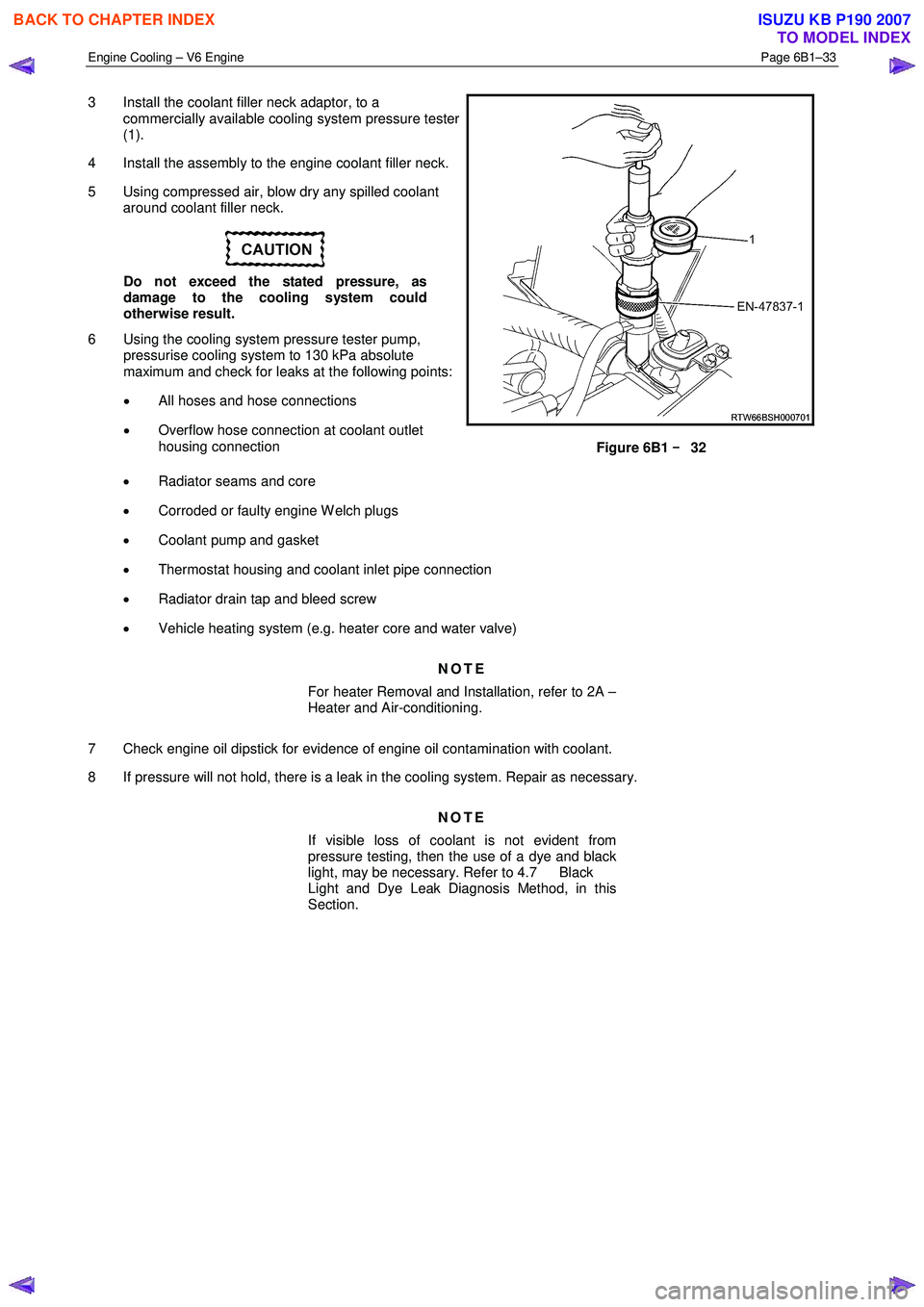
3 Install the coolant filler neck adaptor, to a
commercially available cooling system pressure tester
(1).
4 Install the assembly to the engine coolant filler neck.
5 Using compressed air, blow dry any spilled coolant around coolant filler neck.
Do not exceed the stated pressure, as
damage to the cooling system could
otherwise result.
6 Using the cooling system pressure tester pump, pressurise cooling system to 130 kPa absolute
maximum and check for leaks at the following points:
• All hoses and hose connections
• Overflow hose connection at coolant outlet
housing connection
Figure 6B1 –
––
–
32
• Radiator seams and core
• Corroded or faulty engine W elch plugs
• Coolant pump and gasket
• Thermostat housing and coolant inlet pipe connection
• Radiator drain tap and bleed screw
• Vehicle heating system (e.g. heater core and water valve)
NOTE
For heater Removal and Installation, refer to 2A –
Heater and Air-conditioning.
7 Check engine oil dipstick for evidence of engine oil contamination with coolant.
8 If pressure will not hold, there is a leak in the cooling system. Repair as necessary.
NOTE
If visible loss of coolant is not evident from
pressure testing, then the use of a dye and black
light, may be necessary. Refer to 4.7 Black
Light and Dye Leak Diagnosis Method, in this
Section.
BACK TO CHAPTER INDEX
TO MODEL INDEX
ISUZU KB P190 2007
Page 3170 of 6020
Engine Cooling – V6 Engine Page 6B1–35
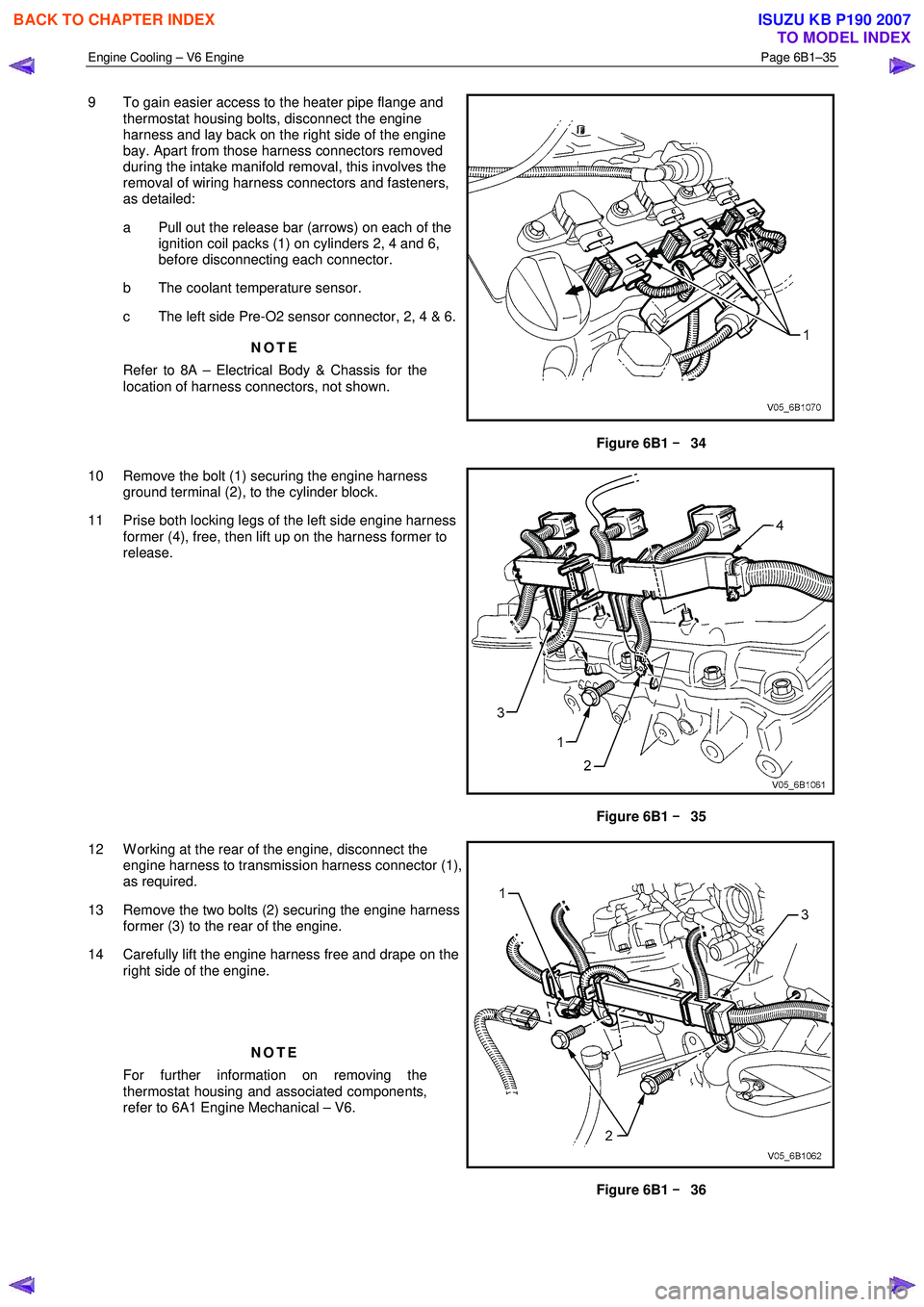
9 To gain easier access to the heater pipe flange and
thermostat housing bolts, disconnect the engine
harness and lay back on the right side of the engine
bay. Apart from those harness connectors removed
during the intake manifold removal, this involves the
removal of wiring harness connectors and fasteners,
as detailed:
a Pull out the release bar (arrows) on each of the ignition coil packs (1) on cylinders 2, 4 and 6,
before disconnecting each connector.
b The coolant temperature sensor.
c The left side Pre-O2 sensor connector, 2, 4 & 6.
NOTE
Refer to 8A – Electrical Body & Chassis for the
location of harness connectors, not shown.
Figure 6B1 –
––
–
34
10 Remove the bolt (1) securing the engine harness ground terminal (2), to the cylinder block.
11 Prise both locking legs of the left side engine harness former (4), free, then lift up on the harness former to
release.
Figure 6B1 –
––
–
35
12 W orking at the rear of the engine, disconnect the engine harness to transmission harness connector (1),
as required.
13 Remove the two bolts (2) securing the engine harness former (3) to the rear of the engine.
14 Carefully lift the engine harness free and drape on the right side of the engine.
NOTE
For further information on removing the
thermostat housing and associated components,
refer to 6A1 Engine Mechanical – V6.
Figure 6B1 –
––
–
36
BACK TO CHAPTER INDEX
TO MODEL INDEX
ISUZU KB P190 2007
Page 3192 of 6020
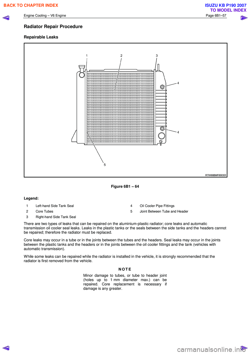
Engine Cooling – V6 Engine Page 6B1–57
Radiator Repair Procedure
Repairable Leaks
Figure 6B1 – 64
Legend:
1 Left-hand Side Tank Seal
2 Core Tubes
3 Right-hand Side Tank Seal 4 Oil Cooler Pipe Fittings
5 Joint Between Tube and Header
There are two types of leaks that can be repaired on the aluminium-plastic radiator; core leaks and automatic
transmission oil cooler seal leaks. Leaks in the plastic tanks or the seals between the side tanks and the headers cannot
be repaired; therefore the radiator must be replaced.
Core leaks may occur in a tube or in the joints between the tubes and the headers. Seal leaks may occur in the joints
between the plastic tanks and the headers or in the joints between the oil cooler fittings and the tank (vehicles with
automatic transmission).
W hile some leaks can be repaired while the radiator is installed in the vehicle, it is strongly recommended that the
radiator is first removed from the vehicle.
NOTE
Minor damage to tubes, or tube to header joint
(holes up to 1 mm diameter max.) can be
repaired. Core replacement is necessary if
damage is any greater.
BACK TO CHAPTER INDEX
TO MODEL INDEX
ISUZU KB P190 2007
Page 3194 of 6020
Engine Cooling – V6 Engine Page 6B1–59
General Core Repair
NOTE
The need for careful preparation of the surface in
the repair area cannot be over-emphasised. If the
leak area surface is not clean, the repair material
will not adhere to the surface.
Refer to ‘
‘‘
‘
Environmental Issues ’
’’
’
in 3.1
Service Notes, before draining the coolant.
1 Drain the coolant from the system. Refer to 3.3 Draining and Filling Cooling System in this Section.
2 Remove the radiator. Refer to 3.15 Radiator in this Section.
3 If necessary, carefully cut away fins to expose the damaged area.
NOTE
Do not cut away more than 25 mm total fin
material.
4 Clean away dirt etc. with water. Dry the affected area using hot air from a hair drier.
Do not apply flame to dry damaged area.
5 Clean affected area with petrol to remove any traces of oil.
6 Thoroughly stir contents of repair agent.
NOTE
In cases of extended shelf life, the silicon in
solution may separate from the thinner base.
Should this occur, mix contents well until agent is
again homogeneous.
7 Apply repair agent sparingly to damaged area. Do not apply an excessive amount, as this will cause blockage of the radiator tube.
NOTE
Use a clean, dry wooden applicator to 'DRIP'
agent onto damaged area of radiator.
8 Allow radiator to stand in a clean, dry area for a minimum of 3 hours (at ambient temperature of 20 – 30 ° C) with
adequate ventilation.
NOTE
Do not apply heat or flame to promote drying.
9 Reinstall the radiator. Refer to 3.15 Radiator in this Section.
BACK TO CHAPTER INDEX
TO MODEL INDEX
ISUZU KB P190 2007
Page 3195 of 6020
Engine Cooling – V6 Engine Page 6B1–60
Transmission Oil Cooler Leak Test
If the transmission oil cooler is suspected of leaking oil, test it before the radiator is replaced, as follows:
1 Disconnect oil cooler pipes at the flexible hose connections. Refer to 3.14 Flexible Transmission Cooler Hose, in this Section.
2 Plug one of the connections, using a blocked pipe fitting and attach an air supply to the other flexible hose.
3 Remove coolant filler cap and check that the coolant is filled to the coolant filler cap filler neck.
4 Apply air pressure gradually, increasing up to an absolute maximum of 110 kPa. If bubbles appear in radiator neck, the oil cooler is leaking and the radiator assembly must be replaced.
Transmission Oil Cooler Seal Replacement.
It is strongly recommended that the transmission oil cooler connector fittings to the right-hand side radiator header tank,
not be disturbed. If coolant is found to leak from either of these two areas, then the radiator should be replaced.
BACK TO CHAPTER INDEX
TO MODEL INDEX
ISUZU KB P190 2007