2007 ISUZU KB P190 oil
[x] Cancel search: oilPage 3090 of 6020
Engine Mechanical – V6 Page 6A1–313
Page 6A1–313
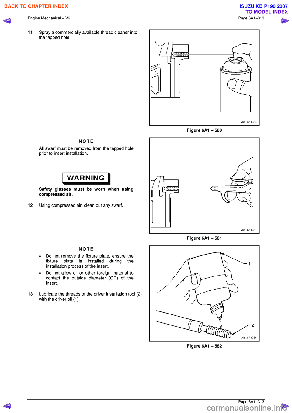
11 Spray a commercially available thread cleaner into
the tapped hole.
Figure 6A1 – 580
NOTE
All swarf must be removed from the tapped hole
prior to insert installation.
Safety glasses must be worn when using
compressed air.
12 Using compressed air, clean out any swarf.
Figure 6A1 – 581
NOTE
• Do not remove the fixt ure plate, ensure the
fixture plate is in stalled during the
installation process of the insert.
• Do not allow oil or other foreign material to
contact the outside diam eter (OD) of the
insert.
13 Lubricate the threads of the driver installation tool (2)
with the driver oil (1).
Figure 6A1 – 582
BACK TO CHAPTER INDEX
TO MODEL INDEX
ISUZU KB P190 2007
Page 3096 of 6020
Engine Mechanical – V6 Page 6A1–319
Page 6A1–319
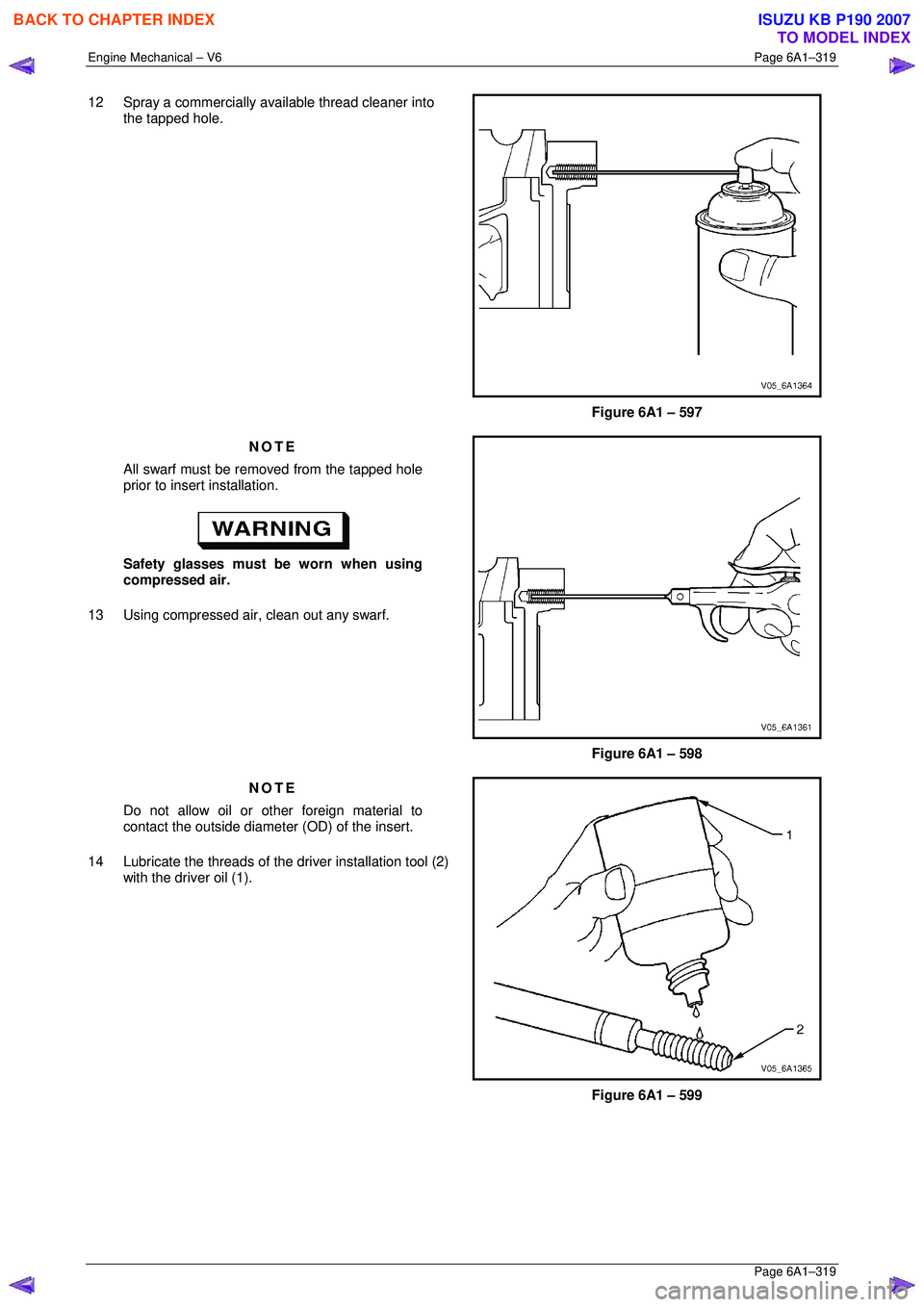
12 Spray a commercially available thread cleaner into
the tapped hole.
Figure 6A1 – 597
NOTE
All swarf must be removed from the tapped hole
prior to insert installation.
Safety glasses must be worn when using
compressed air.
13 Using compressed air, clean out any swarf.
Figure 6A1 – 598
NOTE
Do not allow oil or other foreign material to
contact the outside diameter (OD) of the insert.
14 Lubricate the threads of the driver installation tool (2)
with the driver oil (1).
Figure 6A1 – 599
BACK TO CHAPTER INDEX
TO MODEL INDEX
ISUZU KB P190 2007
Page 3121 of 6020
Engine Mechanical – V6 Page 6A1–344
Page 6A1–344
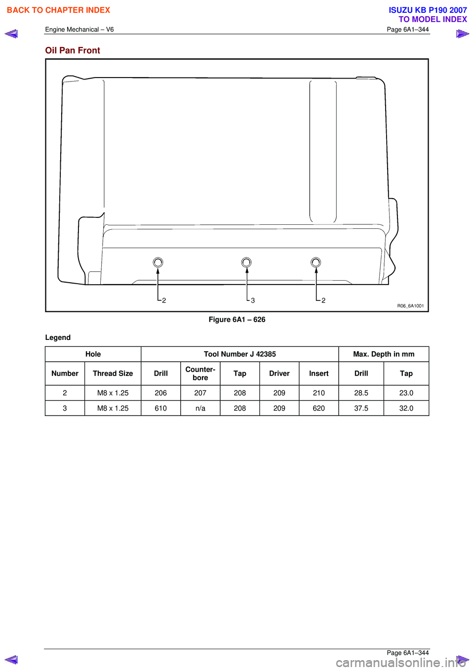
Oil Pan Front
Figure 6A1 – 626
Legend Hole Tool Number J 42385 Max. Depth in mm
Number Thread Size Drill Counter-
bore Tap Driver Insert Drill Tap
2 M8 x 1.25 206 207 208 209 210 28.5 23.0
3 M8 x 1.25 610 n/a 208 209 620 37.5 32.0
BACK TO CHAPTER INDEX
TO MODEL INDEX
ISUZU KB P190 2007
Page 3122 of 6020
Engine Mechanical – V6 Page 6A1–345
Page 6A1–345
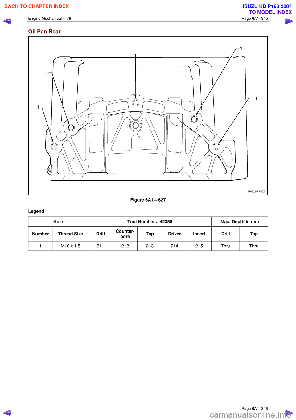
Oil Pan Rear
Figure 6A1 – 627
Legend Hole Tool Number J 42385 Max. Depth in mm
Number Thread Size Drill Counter-
bore Tap Driver Insert Drill Tap
1 M10 x 1.5 211 212 213 214 215 Thru Thru
BACK TO CHAPTER INDEX
TO MODEL INDEX
ISUZU KB P190 2007
Page 3123 of 6020
Engine Mechanical – V6 Page 6A1–346
Page 6A1–346
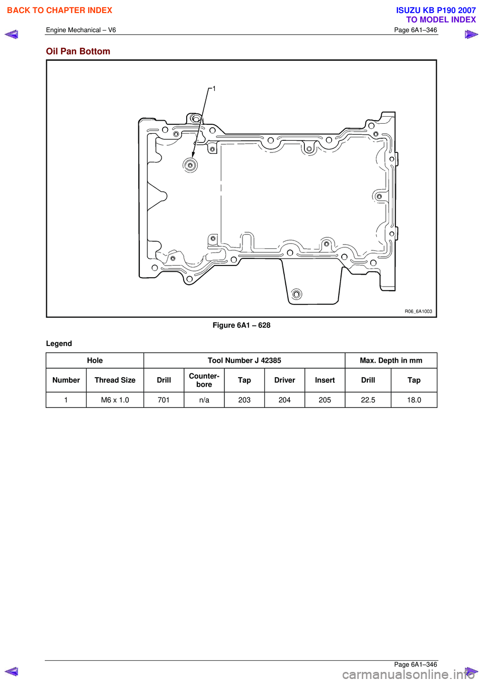
Oil Pan Bottom
Figure 6A1 – 628
Legend Hole Tool Number J 42385 Max. Depth in mm
Number Thread Size Drill Counter-
bore Tap Driver Insert Drill Tap
1 M6 x 1.0 701 n/a 203 204 205 22.5 18.0
BACK TO CHAPTER INDEX
TO MODEL INDEX
ISUZU KB P190 2007
Page 3125 of 6020
Engine Mechanical – V6 Page 6A1–348
Page 6A1–348
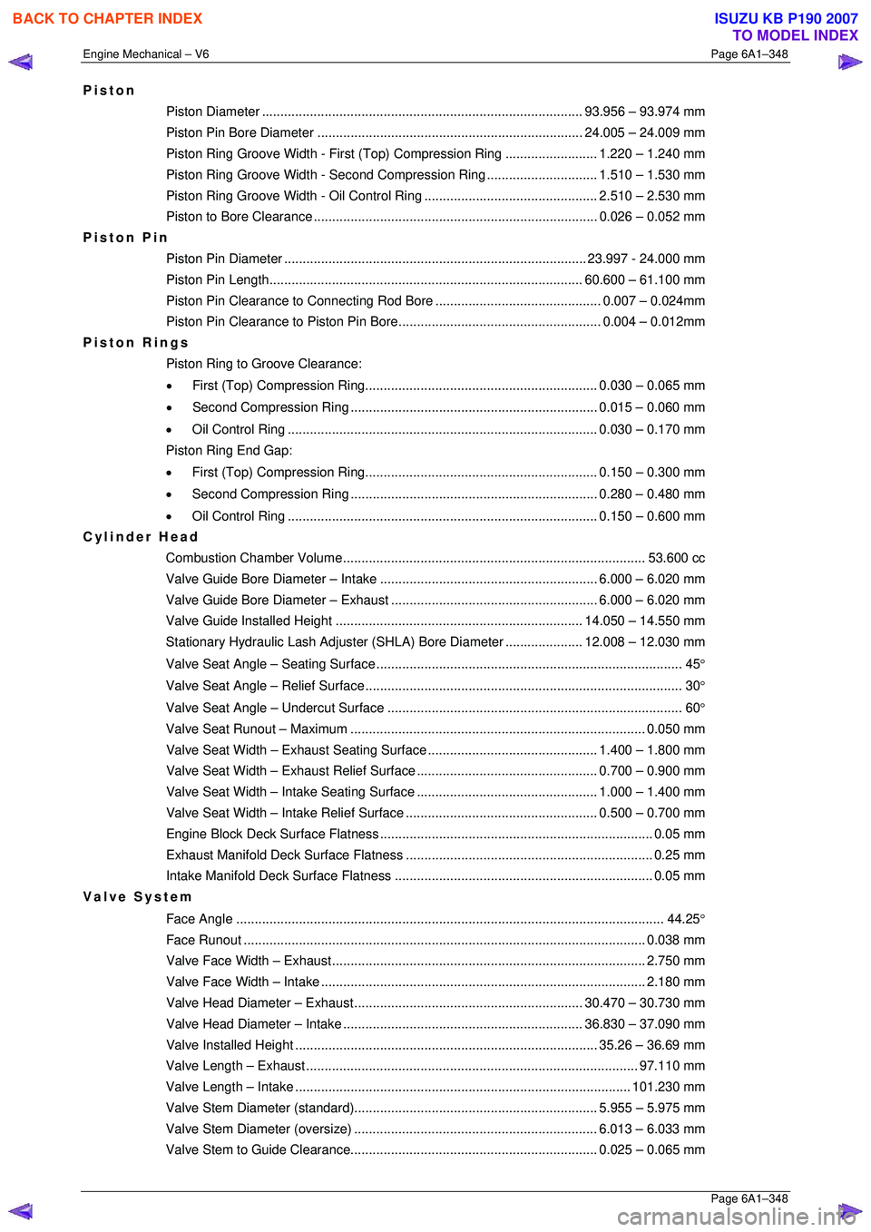
Piston
Piston Diameter ....................................................................................... 93. 956 – 93.974 mm
Piston Pin Bore Diame ter ........................................................................ 24.005 – 24.009 mm
Piston Ring Groove Width - First (Top) Compression Ring ......................... 1.220 – 1.240 mm
Piston Ring Groove Width - Second Compression Ring.............................. 1. 510 – 1.530 mm
Piston Ring Groove Width - Oil Control Ring ............................................... 2. 510 – 2.530 mm
Piston to Bore Clear ance ............................................................................. 0.026 – 0.052 mm
Piston Pin
Piston Pin Diamet er .................................................................................. 23.997 - 24.000 mm
Piston Pin Length ..................................................................................... 60. 600 – 61.100 mm
Piston Pin Clearance to Connec ting Rod Bore............................................. 0. 007 – 0.024mm
Piston Pin Clearance to Pist on Pin Bore....................................................... 0. 004 – 0.012mm
Piston Rings
Piston Ring to Groove Clearance:
• First (Top) Compression Ring............................................................... 0. 030 – 0.065 mm
• Second Compression Ring ................................................................... 0.015 – 0.060 mm
• Oil Control Ring .................................................................................... 0. 030 – 0.170 mm
Piston Ring End Gap:
• First (Top) Compression Ring............................................................... 0. 150 – 0.300 mm
• Second Compression Ring ................................................................... 0.280 – 0.480 mm
• Oil Control Ring .................................................................................... 0. 150 – 0.600 mm
Cylinder Head
Combustion Chambe r Volume.................................................................................. 53. 600 cc
Valve Guide Bore Diameter – Intake ........................................................... 6.000 – 6.020 mm
Valve Guide Bore Diameter – Exhaust ........................................................ 6.000 – 6.020 mm
Valve Guide Installed Height................................................................... 14. 050 – 14.550 mm
Stationary Hydraulic Lash Adjuster (S HLA) Bore Diameter .....................12.008 – 12.030 mm
Valve Seat Angle – Seating Surface ................................................................................... 45 °
Valve Seat Angle – Relief Surface...................................................................................... 30 °
Valve Seat Angle – Un dercut Surface ................................................................................ 60 °
Valve Seat Runout – Maximum................................................................................ 0. 050 mm
Valve Seat Width – Exhaust S eating Surface.............................................. 1. 400 – 1.800 mm
Valve Seat Width – Exhaust Re lief Surface................................................. 0. 700 – 0.900 mm
Valve Seat Width – Intake Se ating Surface................................................. 1. 000 – 1.400 mm
Valve Seat Width – Intake Relief Surface.................................................... 0. 500 – 0.700 mm
Engine Block Deck Surf ace Flatness .......................................................................... 0. 05 mm
Exhaust Manifold Deck Su rface Flatness ................................................................... 0. 25 mm
Intake Manifold Deck Su rface Flatness ...................................................................... 0. 05 mm
Valve System
Face Angle .................................................................................................................... 4 4.25°
Face Run out ............................................................................................................. 0.038 mm
Valve Face Width – Exhaust..................................................................................... 2. 750 mm
Valve Face Width – Intake........................................................................................ 2. 180 mm
Valve Head Diameter – Ex haust .............................................................. 30.470 – 30.730 mm
Valve Head Diameter – Intake ................................................................. 36. 830 – 37.090 mm
Valve Installed He ight .................................................................................. 35.26 – 36.69 mm
Valve Length – Exhaust.......................................................................................... 97. 110 mm
Valve Length – Intake ........................................................................................... 101.230 mm
Valve Stem Diameter (s tandard).................................................................. 5. 955 – 5.975 mm
Valve Stem Diameter (o versize).................................................................. 6.013 – 6.033 mm
Valve Stem to Guide Clearance................................................................... 0. 025 – 0.065 mm
BACK TO CHAPTER INDEX
TO MODEL INDEX
ISUZU KB P190 2007
Page 3126 of 6020
Engine Mechanical – V6 Page 6A1–349
Page 6A1–349
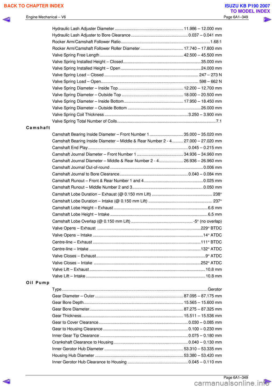
Hydraulic Lash Adjuster Diameter ........................................................... 11.986 – 12.000 mm
Hydraulic Lash Adjuster to Bore Clearance................................................. 0. 037 – 0.041 mm
Rocker Arm/Camshaft Fo llower Ratio............................................................................. 1. 68:1
Rocker Arm/Camshaft Follower Ro ller Diameter..................................... 17. 740 – 17.800 mm
Valve Spring Free Le ngth ........................................................................ 42.500 – 45.500 mm
Valve Spring Installed He ight – Closed................................................................... 35. 000 mm
Valve Spring Installed Height – Open ..................................................................... 24.000 mm
Valve Spring Load – Closed................................................................................. 247 – 273 N
Valve Spring Load – Open.................................................................................... 598 – 662 N
Valve Spring Diameter – In side Top ........................................................ 12.200 – 12.700 mm
Valve Spring Diameter – Ou tside Top ..................................................... 18.000 – 20.500 mm
Valve Spring Diameter – In side Bottom ................................................... 17.950 – 18.450 mm
Valve Spring Diameter – Outside Bottom ............................................................... 26. 000 mm
Valve Spring Coil Thi ckness ........................................................................ 3.250 – 3.900 mm
Valve Spring Total Nu mber of Coils..................................................................................... 7.1
Camshaft
Camshaft Bearing Inside Diameter – Front Number 1 ............................. 35. 000 – 35.020 mm
Camshaft Bearing Inside Diam eter – Middle & Rear Number 2 - 4..........27.000 – 27.020 mm
Camshaft End Play ...................................................................................... 0. 045 – 0.215 mm
Camshaft Journal Diameter – Fr ont Number 1........................................ 34. 936 – 34.960 mm
Camshaft Journal Diameter – Middle & Rear Number 2 - 4..................... 26. 936 – 26.960 mm
Camshaft Journal Ou t-of-round................................................................................ 0. 006 mm
Camshaft Journal to Bore Clearance ........................................................... 0.040 – 0.084 mm
Camshaft Runout – Front & R ear Number 1 and 4................................................... 0. 025 mm
Camshaft Runout – Middle Number 2 and 3............................................................ .0 .050 mm
Camshaft Lobe Duration – Ex haust (@ 0.150 mm Lift) .................................................... 238 °
Camshaft Lobe Duration – In take (@ 0.150 mm Lift) ....................................................... 237 °
Camshaft Lobe Height – Exhaust ................................................................................. 6.6 mm
Camshaft Lobe Height – Intake.................................................................................... 6.5 mm
Camshaft Lobe Overlap (@ 0.150 mm Lift) ..................................................... -5 ° (no overlap)
Valve Opens – Exhaust .........................................................................................229 ° BTDC
Valve Opens – Intake ...............................................................................................14 ° ATDC
Centre-line – Exhaust .............................................................................................111 ° BTDC
Centre-line – Intake ................................................................................................132 ° ATDC
Valve Closes – Exhaust ..............................................................................................9 ° ATDC
Valve Closes – Intake ............................................................................................252 ° ATDC
Valve Lift – Ex haust .................................................................................................... 10.8 mm
Valve Lift – Intake....................................................................................................... 10. 8 mm
Oil Pump
Type........................................................................................................................... ...Gerotor
Gear Diameter – Ou ter ............................................................................ 87.095 – 87.175 mm
Gear Bore Dept h...................................................................................... 15. 565 – 15.600 mm
Gear Bore Diamet er................................................................................. 87.275 – 87.325 mm
Gear Thickness ........................................................................................ 15. 511 – 15.536 mm
Gear to Cover Clear ance ............................................................................. 0.030 – 0.085 mm
Gear to Housing Cle arance......................................................................... 0. 100 – 0.230 mm
Inner Gear Tip Clear ance ............................................................................ 0.075 – 0.180 mm
Crankshaft Clearance to Housing................................................................ 0. 040 – 0.130 mm
Inner Gerotor Hub Di ameter.................................................................... 53. 310 – 53.335 mm
Housing Hub Diamet er ............................................................................ 53.380 – 53.420 mm
Inner Gerotor Hub Clearance to Housing .................................................... 0. 045 – 0.110 mm
BACK TO CHAPTER INDEX
TO MODEL INDEX
ISUZU KB P190 2007
Page 3127 of 6020
Engine Mechanical – V6 Page 6A1–350
Page 6A1–350
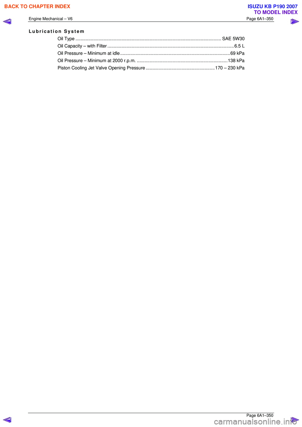
Lubrication System
Oil Type.................................................................................................................. SAE 5 W30
Oil Capacity – with Filter................................................................................................... 6. 5 L
Oil Pressure – Mini mum at idle ......................................................................................69 kPa
Oil Pressure – Minimum at 2000 r.p.m. ....................................................................... 138 kPa
Piston Cooling Jet Valve Op ening Pressure...................................................... 170 – 230 kPa
BACK TO CHAPTER INDEX
TO MODEL INDEX
ISUZU KB P190 2007