Page 3032 of 6020
Engine Mechanical – V6 Page 6A1–255
Page 6A1–255
Disassemble
1 Remove the following:
2 Oil pan drain plug (7) and sleeve (8).
3 Oil level sensor (9).
4 Crankshaft oil deflector bolts (6) and remove the deflector.
5 Oil pump suction pipe bolts (5) and the suction pipe (3).
6 Oil pump suction pipe gasket (4) from the suction pipe and discard.
Figure 6A1 – 444
Clean
1 Remove any remaining thread sealant, gasket material or sealant using a commercially available wooden or plastic
scraper.
2 Clean the oil pan and oil pan components in solvent.
3 Clean out debris from the bolt holes.
Safety glasses must be worn when using
compressed air.
4 Dry the oil pan and oil pan components with compressed air.
BACK TO CHAPTER INDEX
TO MODEL INDEX
ISUZU KB P190 2007
Page 3033 of 6020

Engine Mechanical – V6 Page 6A1–256
Page 6A1–256
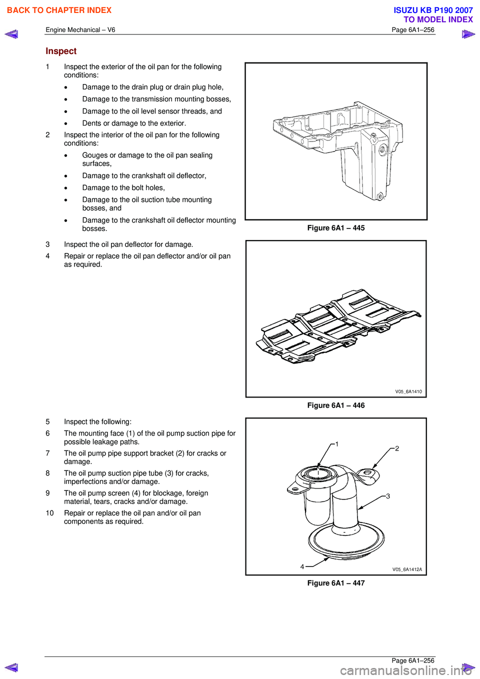
Inspect
1 Inspect the exterior of the oil pan for the following
conditions:
• Damage to the drain plug or drain plug hole,
• Damage to the transmission mounting bosses,
• Damage to the oil level sensor threads, and
• Dents or damage to the exterior.
2 Inspect the interior of the oil pan for the following conditions:
• Gouges or damage to the oil pan sealing
surfaces,
• Damage to the crankshaft oil deflector,
• Damage to the bolt holes,
• Damage to the oil suction tube mounting
bosses, and
• Damage to the crankshaft oil deflector mounting
bosses.
Figure 6A1 – 445
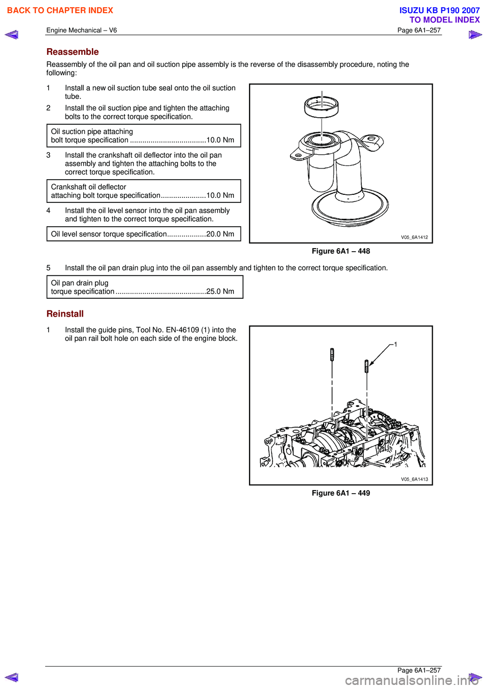
3 Inspect the oil pan deflector for damage.
4 Repair or replace the o il pan deflector and/or oil pan
as required.
Figure 6A1 – 446
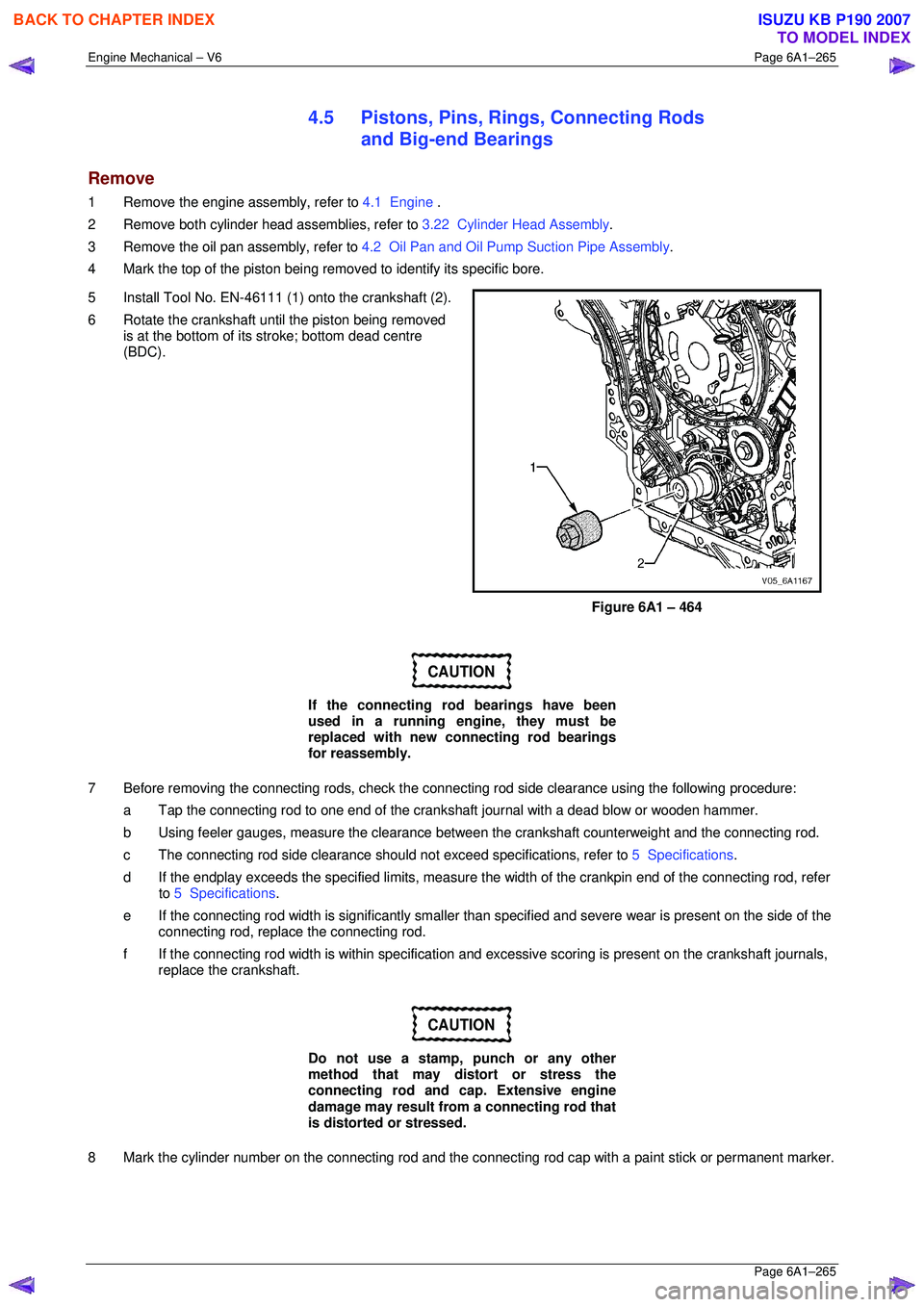
5 Inspect the following:
6 The mounting face (1) of the oil pump suction pipe for possible leakage paths.
7 The oil pump pipe support bracket (2) for cracks or damage.
8 The oil pump suction pipe tube (3) for cracks, imperfections and/or damage.
9 The oil pump screen (4) for blockage, foreign material, tears, cracks and/or damage.
10 Repair or replace the oil pan and/or oil pan components as required.
Figure 6A1 – 447
BACK TO CHAPTER INDEX
TO MODEL INDEX
ISUZU KB P190 2007
Page 3034 of 6020

Engine Mechanical – V6 Page 6A1–257
Page 6A1–257
Reassemble
Reassembly of the oil pan and oil suction pipe assembly is the reverse of the disassembly procedure, noting the
following:
1 Install a new oil suction t ube seal onto the oil suction
tube.
2 Install the oil suction pipe and tighten the attaching bolts to the correct torque specification.
Oil suction pipe attaching
bolt torque specif ication ..................................... 10.0 Nm
3 Install the crankshaft oil deflector into the oil pan
assembly and tighten the attaching bolts to the
correct torque specification.
Crankshaft oil deflector
attaching bolt torque specification ......................10.0 Nm
4 Install the oil level sensor into the oil pan assembly
and tighten to the correct torque specification.
Oil level sensor torque specification...................20.0 Nm
Figure 6A1 – 448
5 Install the oil pan drain plug into the oil pan assemb ly and tighten to the correct torque specification.
Oil pan drain plug
torque specificat ion ............................................ 25.0 Nm
Reinstall
1 Install the guide pins, Tool No. EN-46109 (1) into the
oil pan rail bolt hole on each side of the engine block.
Figure 6A1 – 449
BACK TO CHAPTER INDEX
TO MODEL INDEX
ISUZU KB P190 2007
Page 3035 of 6020
Engine Mechanical – V6 Page 6A1–258
Page 6A1–258
2 Place a 3mm bead (1) of RTV sealant on the cylinder
block pan rail and crankshaft rear oil seal housing to
oil pan mating surfaces.
3 Position the oil pan onto the cylinder block.
4 Remove the guide pins, Tool No. EN-46109 from the cylinder block.
Figure 6A1 – 450
5 Loosely install the oil pan bolts.
6 Tighten the oil pan attaching bolts to the correct torque specification and in the sequence shown.
Oil pan to cylinder block attaching
bolt (1 – 11) torque specif ication............. 20.0 – 26.0 Nm
Oil pan to crankshaft rear oil
seal housing attaching bolt (12 – 13)
torque specificatio n ................................... 8. 0 – 12.0 Nm
Figure 6A1 – 451
BACK TO CHAPTER INDEX
TO MODEL INDEX
ISUZU KB P190 2007
Page 3039 of 6020
Engine Mechanical – V6 Page 6A1–262
Page 6A1–262
4.4 Crankshaft Rear Seal and Plate
Assembly
Remove
1 Remove the engine assembly, refer to 4.1 Engine .
2 Remove the flexplat e assembly, refer to 4.3 Flexplate Assembly .
3 Remove the engine oil pan assembly, refer to 4.2 Oil Pan and Oil Pump Suction Pipe Assembly.
4 Remove the five bolts (1) attaching the crankshaft rear seal housing to the rear of the cylinder block (2).
Figure 6A1 – 457
5 Shear the RTV sealant usi ng the prise points located
at the edge of the crankshaft rear oil seal housing,
Figure 6A1 – 458
BACK TO CHAPTER INDEX
TO MODEL INDEX
ISUZU KB P190 2007
Page 3040 of 6020
Engine Mechanical – V6 Page 6A1–263
Page 6A1–263
6 Remove the crankshaft rear oil seal housing (1) from
the cylinder block (2).
Figure 6A1 – 459
Reinstall
1 Install the guide pins, Tool No. EN-46109 (1) into the two crankshaft rear oil seal housing bolt holes of the
cylinder block (2).
Figure 6A1 – 460
2 Apply a 3mm bead (1) of RTV sealant to the crankshaft rear oil seal housing.
Figure 6A1 – 461
BACK TO CHAPTER INDEX
TO MODEL INDEX
ISUZU KB P190 2007
Page 3041 of 6020
Engine Mechanical – V6 Page 6A1–264
Page 6A1–264
3 Install the crankshaft rear oil seal housing (1) to the
cylinder block (2).
NOTE
• Do not allow any engine oil onto the cylinder
block mating surface, where the crankshaft
rear oil seal housing is to be installed.
• A seal-protector is provided with the new
crankshaft rear seal and housing assembly.
Do not remove the seal protector from the
crankshaft rear oil seal housing until the
crankshaft rear oil seal housing is fully in
position.
4 Remove the guide pins from the cylinder block.
Figure 6A1 – 462
5 Install the crankshaft rear oil seal housing attaching bolts (1) to the cylinder block (2) and tighten to the
correct torque specification.
Crankshaft rear oil seal housing
attaching bolt torque spec ification ............. 8.0 – 12.0 Nm
Figure 6A1 – 463
BACK TO CHAPTER INDEX
TO MODEL INDEX
ISUZU KB P190 2007
Page 3042 of 6020

Engine Mechanical – V6 Page 6A1–265
Page 6A1–265
4.5 Pistons, Pins, Rings, Connecting Rods
and Big-end Bearings
Remove
1 Remove the engine assembly, refer to 4.1 Engine .
2 Remove both cylinder head assemblies, refer to 3.22 Cylinder Head Assembly.
3 Remove the oil pan assembly, refer to 4.2 Oil Pan and Oil Pump Suction Pipe Assembly .
4 Mark the top of the piston being remo ved to identify its specific bore.
5 Install Tool No. EN-46111 (1) onto the crankshaft (2).
6 Rotate the crankshaft until the piston being removed is at the bottom of its stroke; bottom dead centre
(BDC).
Figure 6A1 – 464
CAUTION
If the connecting rod bearings have been
used in a running engine, they must be
replaced with new connecting rod bearings
for reassembly.
7 Before removing the connecting rods, check the connec ting rod side clearance using the following procedure:
a Tap the connecting rod to one end of the cranks haft journal with a dead blow or wooden hammer.
b Using feeler gauges, measure the clearance between the crankshaft counterweight and the connecting rod.
c The connecting rod side clearance should not exceed specifications, refer to 5 Specifications.
d If the endplay exceeds the specified limits, measure the width of the crankpin end of the connecting rod, refer
to 5 Specifications .
e If the connecting rod width is significantly smaller than specified and severe wear is present on the side of the
connecting rod, replac e the connecting rod.
f If the connecting rod width is within specification and excessive scoring is present on the crankshaft journals,
replace the crankshaft.
CAUTION
Do not use a stamp, punch or any other
method that may distort or stress the
connecting rod and cap. Extensive engine
damage may result from a connecting rod that
is distorted or stressed.
8 Mark the cylinder number on the connec ting rod and the connecting rod cap with a paint stick or permanent marker.
BACK TO CHAPTER INDEX
TO MODEL INDEX
ISUZU KB P190 2007