2007 ISUZU KB P190 oil
[x] Cancel search: oilPage 3012 of 6020
Engine Mechanical – V6 Page 6A1–235
Page 6A1–235
5 Align the cylinder head with the locating pins.
6 Place the cylinder head in position on the deck face.
NOTE
Do not allow oil on the cylinder head bolt
bosses.
CAUTION
Do not reuse the old M11 cylinder head bolts
(1 to 8 inclusive).
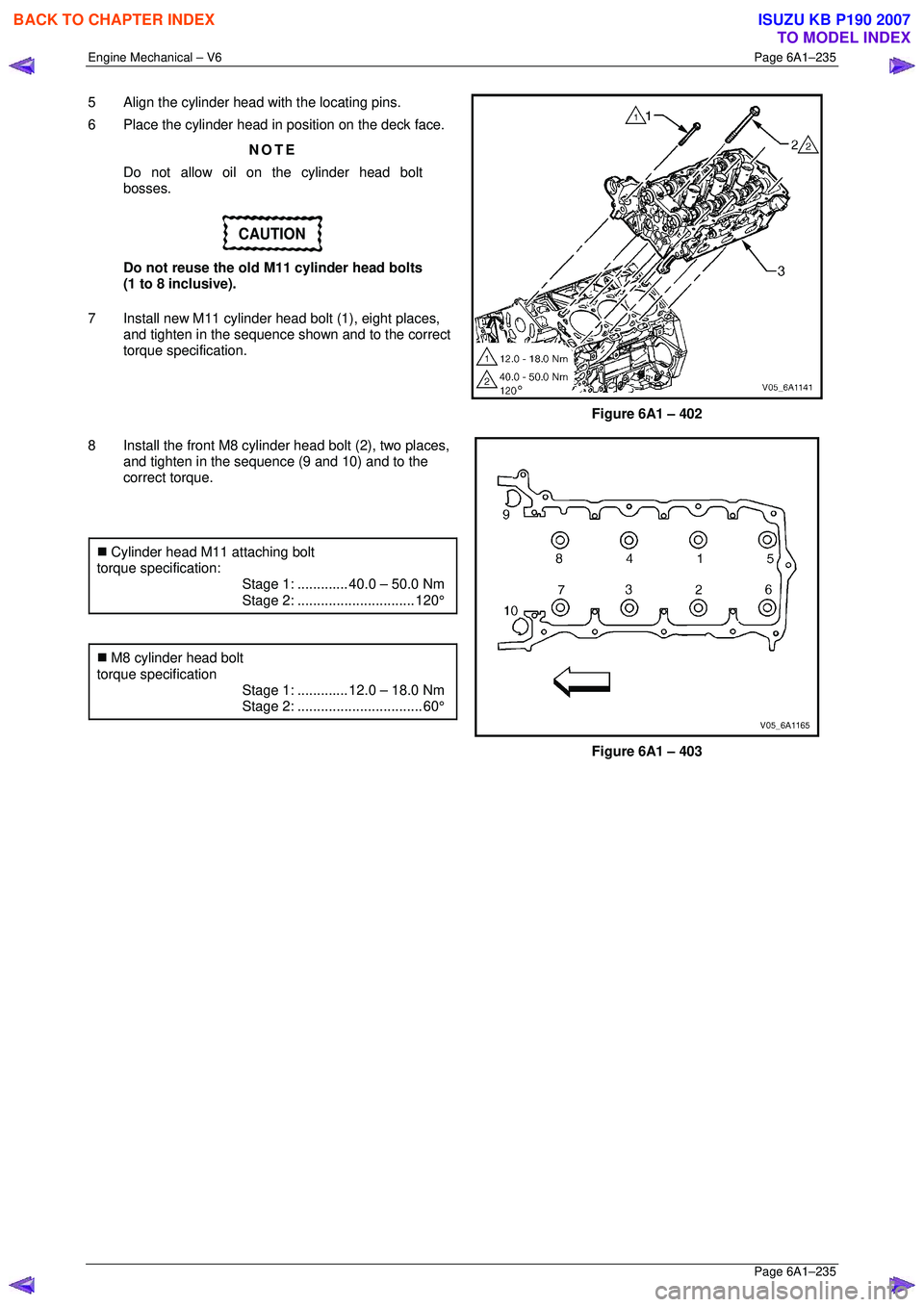
7 Install new M11 cylinder head bolt (1), eight places, and tighten in the sequence shown and to the correct
torque specification.
Figure 6A1 – 402
8 Install the front M8 cylinder head bolt (2), two places, and tighten in the sequence (9 and 10) and to the
correct torque.
�„ Cylinder head M11 attaching bolt
torque specification:
Stage 1:............. 40.0 – 50.0 Nm
Stage 2:.............................. 120°
�„ M8 cylinder head bolt
torque specification
Stage 1:............. 12.0 – 18.0 Nm
Stage 2:................................ 60°
Figure 6A1 – 403
BACK TO CHAPTER INDEX
TO MODEL INDEX
ISUZU KB P190 2007
Page 3016 of 6020
Engine Mechanical – V6 Page 6A1–239
Page 6A1–239
4 Major Service Operations
ATTENTION
The V6 engine is a combination of numerous components, containing machined, honed, polished and lapped
surfaces manufactured on the latest, high technology production equipment. Many of the components
contain tolerances measured in thousa ndths of a millimetre. Consequently, when any e ngine component is to
be serviced, care and cleanliness are extremely important.
Prior to re-assembly of the V6 engi ne, all components must be cleaned and inspected in accordance with the
relevant procedures throughout this section, and replaced or repaired where required.
In addition to cleaning and inspecting components, a liberal coating of engine oil should be applied to friction
surfaces during assembly to protect and lubr icate the surfaces on initial operation.
When performing any service operation contained in this Section, it should be understood that correct
cleaning and protection of machined surfaces and fricti on areas is part of the repair procedure. This is
considered standard workshop practice, even if not specifically stated. Torque values must be used as
specified during reassembly to ensure correct retention of all components.
Through out this section, fastener torque wrench sp ecifications may be accompanied with the following
identification marks:
■ Fasteners must be replaced after loosening.
Fasteners either have micro encapsulated sealant a pplied or incorporate a mechanical thread lock and
should only be re-used once. If in doubt, replacement is recommended.
If one of these identification marks is present alongs ide a fastener torque wrench specification, the
recommendation regarding that fastener must be adhered to.
4.1 Engine Removal
CAUTION
• Allow the engine to cool to at least 50 ° C,
before attempting fastener removal.
• As aluminium has a greater rate of thermal
expansion than that of cast iron,
aluminium bolt hole threads will change
dimension to a larger extent than cast iron
bolt threads.
• If a bolt or other threaded component is
removed before the engine is allowed to
cool to at least 50 ° C, threads could be
pulled from the cylinder block or cylinder
head.
• Do not use impact tools to remove bolts
during engine disassembly. While this may
be common practice with cast iron engine
components, use of th ese tools is likely to
pull the aluminium threads in the cylinder
block or head of this engine.
BACK TO CHAPTER INDEX
TO MODEL INDEX
ISUZU KB P190 2007
Page 3022 of 6020
Engine Mechanical – V6 Page 6A1–245
Page 6A1–245
35 Disconnect the harness connector from the transmission, refer to Section 7B1 Manual Transmission – V6 or
Section 7C1, Section 7C2, Section 7C3 or Section 7C4 for automatic transmission.
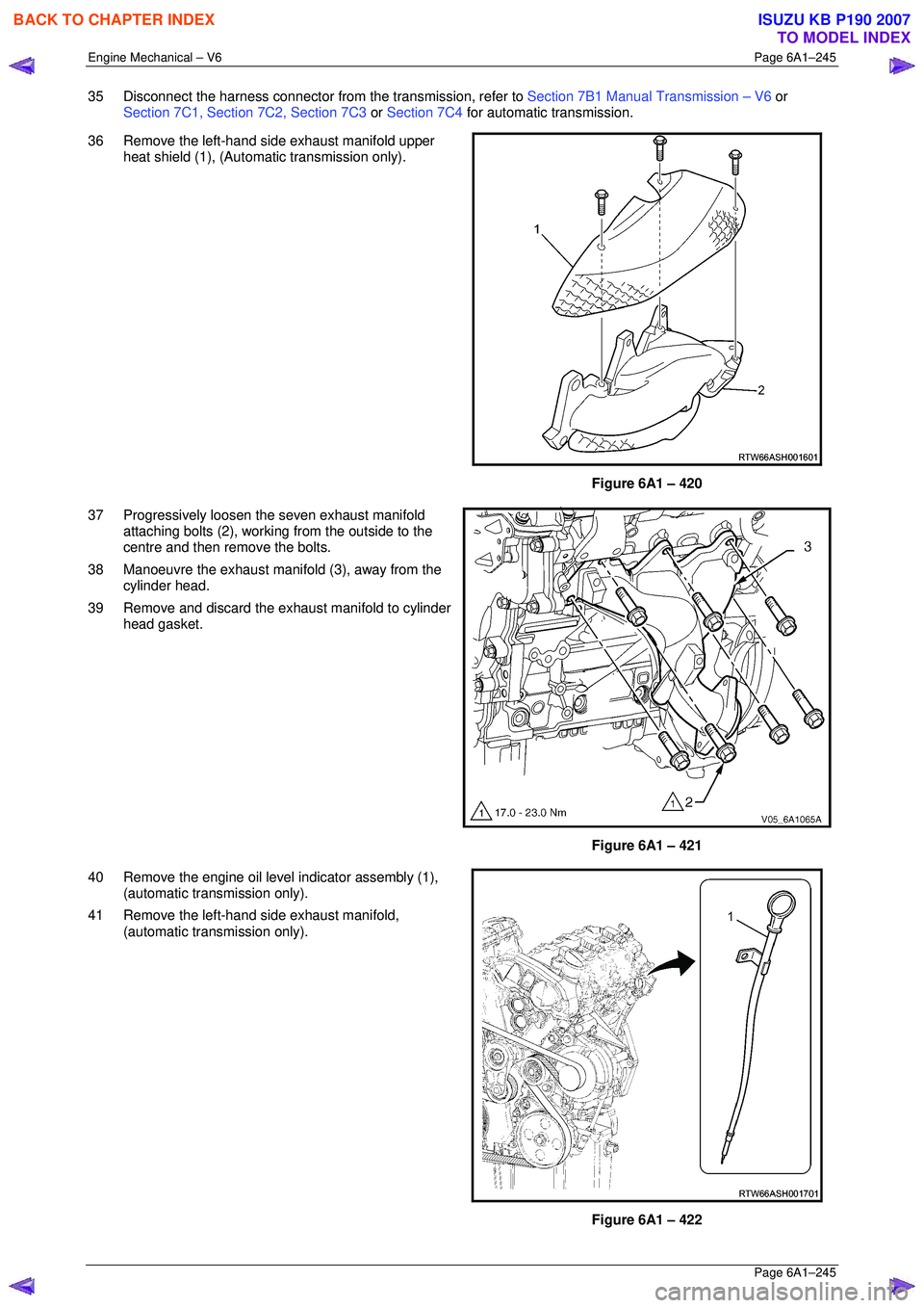
36 Remove the left-hand side exhaust manifold upper heat shield (1), (Automatic transmission only).
Figure 6A1 – 420
37 Progressively loosen the seven exhaust manifold attaching bolts (2), working from the outside to the
centre and then remove the bolts.
38 Manoeuvre the exhaust manifold (3), away from the cylinder head.
39 Remove and discard the exhaust manifold to cylinder head gasket.
Figure 6A1 – 421
40 Remove the engine oil level indicator assembly (1), (automatic transmission only).
41 Remove the left-hand side exhaust manifold, (automatic transmission only).
Figure 6A1 – 422
BACK TO CHAPTER INDEX
TO MODEL INDEX
ISUZU KB P190 2007
Page 3024 of 6020
Engine Mechanical – V6 Page 6A1–247
Page 6A1–247
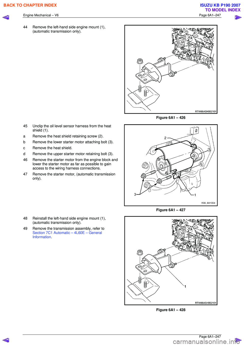
44 Remove the left-hand side engine mount (1),
(automatic transmission only).
Figure 6A1 – 426
45 Unclip the oil level s ensor harness from the heat
shield (1).
a Remove the heat shield retaining screw (2).
b Remove the lower starter motor attaching bolt (3).
c Remove the heat shield.
d Remove the upper starter motor retaining bolt (3).
46 Remove the starter motor from the engine block and lower the starter motor as far as possible to gain
access to the wiring harness connections.
47 Remove the starter moto r, (automatic transmission
only).
Figure 6A1 – 427
48 Reinstall the left-hand side engine mount (1), (automatic transmission only).
49 Remove the transmission assembly, refer to Section 7C1 Automatic – 4L60E – General
Information .
Figure 6A1 – 428
BACK TO CHAPTER INDEX
TO MODEL INDEX
ISUZU KB P190 2007
Page 3025 of 6020
Engine Mechanical – V6 Page 6A1–248
Page 6A1–248
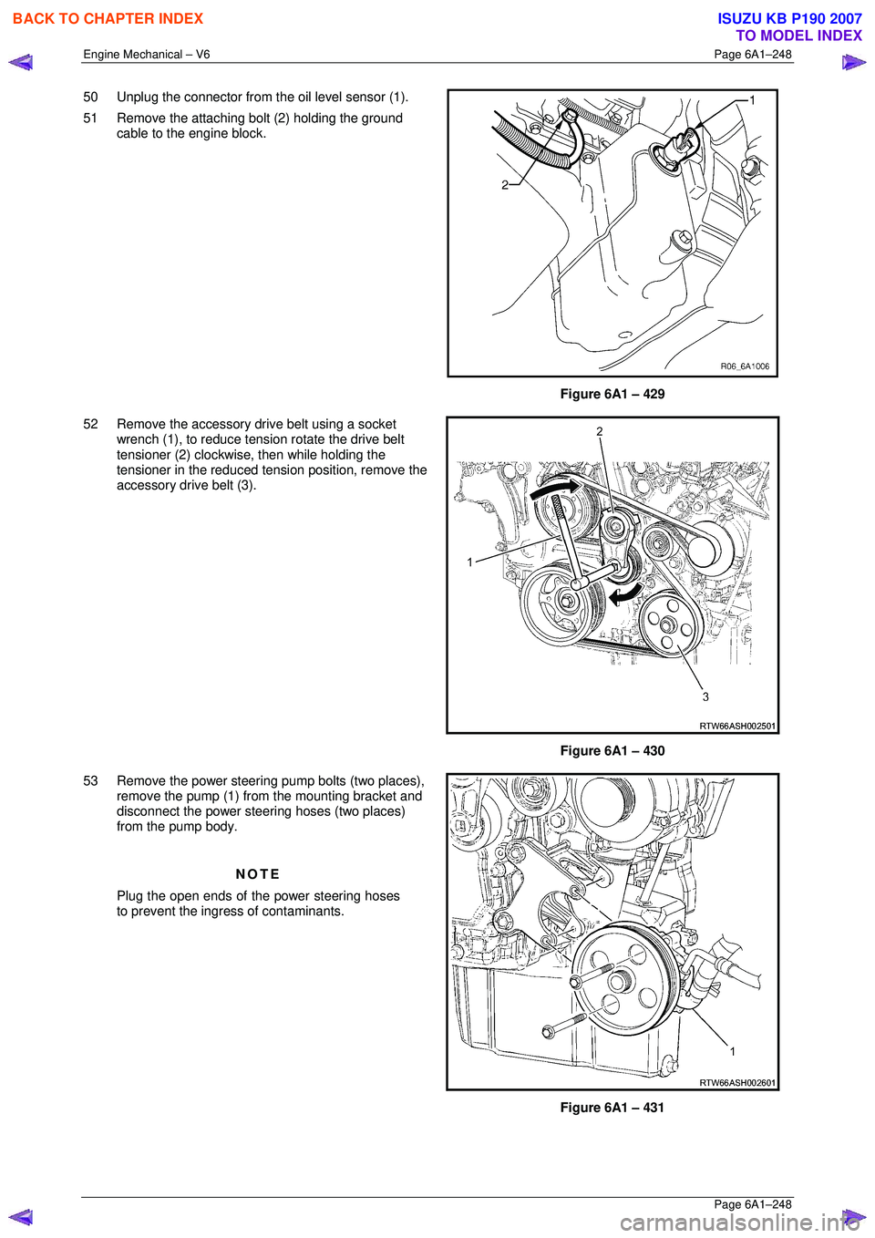
50 Unplug the connector from the oil level sensor (1).
51 Remove the attaching bolt (2) holding the ground cable to the engine block.
Figure 6A1 – 429
52 Remove the accessory drive belt using a socket wrench (1), to reduce tension rotate the drive belt
tensioner (2) clockwise, then while holding the
tensioner in the reduced tens ion position, remove the
accessory drive belt (3).
Figure 6A1 – 430
53 Remove the power steering pump bolts (two places),
remove the pump (1) from the mounting bracket and
disconnect the power steering hoses (two places)
from the pump body.
NOTE
Plug the open ends of the power steering hoses
to prevent the ingre ss of contaminants.
Figure 6A1 – 431
BACK TO CHAPTER INDEX
TO MODEL INDEX
ISUZU KB P190 2007
Page 3029 of 6020
Engine Mechanical – V6 Page 6A1–252
Page 6A1–252
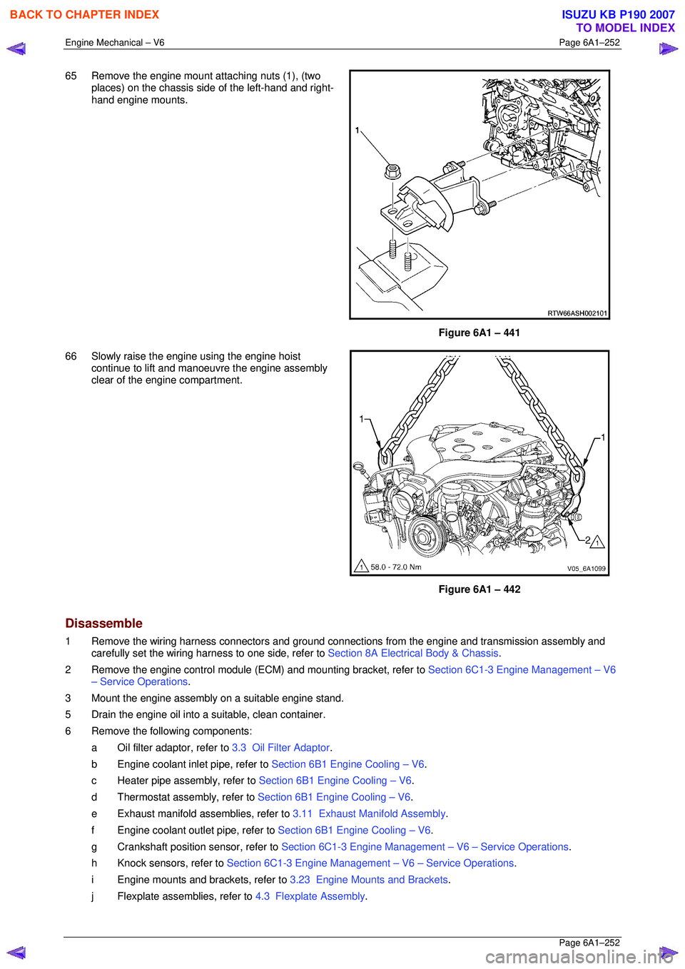
65 Remove the engine mount attaching nuts (1), (two
places) on the chassis si de of the left-hand and right-
hand engine mounts.
Figure 6A1 – 441
66 Slowly raise the engine using the engine hoist continue to lift and manoeuvre the engine assembly
clear of the engine compartment.
Figure 6A1 – 442
Disassemble
1 Remove the wiring harness connectors and ground connec tions from the engine and transmission assembly and
carefully set the wiring harness to one side, refer to Section 8A Electrical Body & Chassis.
2 Remove the engine control module (ECM) and mounting bracket, refer to Section 6C1-3 Engine Management – V6
– Service Operations .
3 Mount the engine assembly on a suitable engine stand.
5 Drain the engine oil into a suitable, clean container.
6 Remove the following components: a Oil filter adaptor, refer to 3.3 Oil Filter Adaptor.
b Engine coolant inlet pipe, refer to Section 6B1 Engine Cooling – V6.
c Heater pipe assembly, refer to Section 6B1 Engine Cooling – V6.
d Thermostat assembly, refer to Section 6B1 Engine Cooling – V6.
e Exhaust manifold a ssemblies, refer to 3.11 Exhaust Manifold Assembly .
f Engine coolant outlet pipe, refer to Section 6B1 Engine Cooling – V6.
g Crankshaft position sensor, refer to Section 6C1-3 Engine Management – V6 – Service Operations.
h Knock sensors, refer to Section 6C1-3 Engine Management – V6 – Service Operations.
i Engine mounts and brackets, refer to 3.23 Engine Mounts and Brackets.
j Flexplate assemblies, refer to 4.3 Flexplate Assembly.
BACK TO CHAPTER INDEX
TO MODEL INDEX
ISUZU KB P190 2007
Page 3030 of 6020
Engine Mechanical – V6 Page 6A1–253
Page 6A1–253
k Timing chains, tensioners, shoes, guides & sprockets, refer to 3.16 Timing Chains, Tensioners, Shoes and
Guides .
l Cylinder head assemblies, refer to 3.22 Cylinder Head Assembly.
m Oil pan assembly, refer to 4.2 Oil Pan and Oil Pump Suction Pipe Assembly .
n Piston and connecting rod assemblies, refer to 4.5 Pistons, Pins, Rings, Connecting Rods and Big-end
Bearings .
o Crankshaft assembly, refer to 4.6 Crankshaft and Main Bearings.
p Piston oil nozzles, refer 4.5 Pistons, Pins, Rings, Connecting Rods and Big-end Bearings .
Reassemble
Reassembly of the engine assembly is the reverse of the disassembly procedure.
Reinstall
Reinstallation of the engine assembly is the revers e to the removal procedure, noting the following:
NOTE
Refer to 6 Torque Wrench Specifications for the
correct torque specifications.
1 Tighten the fasteners to the co rrect torque specification.
Engine ground connector bolt
torque specificat ion ............................................ 10.0 Nm
Power steering high pressure line
attaching bolt torque specification ............. 8.0 – 12.0 Nm
Power steering high pressure line
flare nut torque specif ication ................... 25. 0 – 35.0 Nm
Engine mount to frame attaching bolt
torque specification ................................. 44. 0 – 60.0 Nm
Knock Sensor Attaching Nut
torque specification ............................................ 23.0 Nm
2 Use only the specified engine lubricant type and quantity. It is recommended that a fluorescent oil dye, such as that
contained in J 28481-B, be added to assist in any future oil leak diagnosis.
3 Fill the cooling system with the corre ct quantity and grade of coolant, refer to Section 6B1 Engine Cooling – V6.
4 Check transmission fluid level, replenishing as required, using the specified lubricant for the transmission fitted,
refer to Section 7C1 Automatic – 4L60E – General Information .
5 Disable the ignition system, refer to Section 6C1-3 Engine Management – V6 – Service Operations.
6 Crank the engine several times. Listen for any unusual noises or evidence that parts are binding.
7 Enable the ignition system. Start t he engine and listen for any unusual noises.
8 Check the vehicle oil pressure gauge or warning indica tor and confirm the engine has acceptable oil pressure. If
required, install an oil pressure gauge and m easure the engine oil pressure, refer to 2.19 Engine Oil Pressure
Diagnosis .
9 Run the engine at about 1,000 r. p.m. until the engine has reached normal operating temperature.
10 Listen for any unusual noises.
11 Check for oil, fuel, coolant and exhaust leaks wh ile the engine is running, correcting as required.
12 Perform a final inspection for correct engine oil and coolant levels.
BACK TO CHAPTER INDEX
TO MODEL INDEX
ISUZU KB P190 2007
Page 3031 of 6020
Engine Mechanical – V6 Page 6A1–254
Page 6A1–254
4.2 Oil Pan and Oil Pump Suction Pipe
Assembly
Remove
1 Remove the engine assembly from the vehicle, refer to 4.1 Engine .
2 Separate the engine and transmission assemblies, refer to Section 7C1 Automatic – 4L60E – General Information.
3 Mount the engine assembly on a suitable engine stand.
4 Remove the engine front cover, refer to 3.15 Front Cover Assembly.
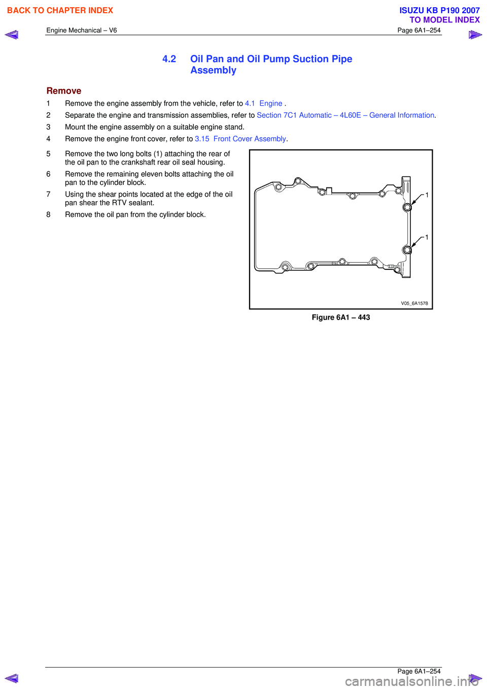
5 Remove the two long bolts (1) attaching the rear of the oil pan to the crankshaft rear oil seal housing.
6 Remove the remaining eleven bolts attaching the oil pan to the cylinder block.
7 Using the shear points loca ted at the edge of the oil
pan shear the RTV sealant.
8 Remove the oil pan from the cylinder block.
Figure 6A1 – 443
BACK TO CHAPTER INDEX
TO MODEL INDEX
ISUZU KB P190 2007